Table of Contents
Advertisement
Advertisement
Table of Contents

Related Manuals for Tyco AutoPulse Z-10


Summary of Contents for Tyco AutoPulse Z-10
- Page 1 Doc. No. 430545 Part No. 579-357 Rev. U *0579357T*...
- Page 2 Blank Page- Back of Front Cover...
-
Page 3: Copyrights And Trademarks
Copyrights and Trademarks ©2005-2018 Johnson Controls. All rights reserved. Specifications and other information shown were current as of publication and are subject to change without notice. SIMPLEX, and the product names listed in this material are marks and/or registered marks. Unauthorized use is strictly prohibited. -
Page 4: Cautions And Warnings
Cautions and Warnings READ AND SAVE THESE INSTRUCTIONS- Follow the instructions in this installation manual. These instructions must be followed to avoid damage to this product and associated equipment. Product operation and reliability depend upon proper installation. DO NOT INSTALL ANY PRODUCT THAT APPEARS DAMAGED- Upon unpacking, inspect the contents of the carton for shipping damage. -
Page 5: Emissions Compliance, Radio Frequency Immunity Safety & Agency Approvals
Emissions Compliance, Radio Frequency Immunity Safety & Agency Approvals This product has been tested and found to comply with the following standards for RF Emissions & Immunity: FCC Part 15A EN55022: 1998, Class A, Emissions (CISPR 22: 1993) ... -
Page 7: Table Of Contents
Table of Contents Copyrights and Trademarks ................... iii Cautions and Warnings ....................iv Emissions Compliance, Radio Frequency Immunity Safety & Agency Approvals ..v Table of Contents ......................vii Chapter 1 Overview ................1-1 Introduction ......................1-1 ... - Page 8 Introduction ......................3-1 In this Chapter ......................3-1 Wiring Initiating Device Circuits ................... 3-2 Guidelines ........................ 3-2 Field Wiring Connections – Two Wire IDCs ............3-4 Wiring Releasing Circuits .................... 3-5 Guidelines ........................ 3-5 ...
- Page 9 Programming the RAC Time Limit Cutout ..............4-11 Overview ........................ 4-11 Programming the RAC Time Limit Cutout, Continued ..........4-12 Programming Manual Release Time Delay ............... 4-13 Overview ........................ 4-13 Programming Abort Switch Operation ............... 4-14 ...
- Page 10 Appendix B TEPG-US/Tyco Safety Products UL Part Number Cross Reference and Approved Valves ............. 1 Appendix C Battery Selection Calculations ........... 4 Introduction ........................4 General ........................4 Battery Selection Calculations ..................2 ...
-
Page 11: Chapter 1 Overview
Overview Introduction The AutoPulse Z-10 (Part No. 430525) Fire Alarm Control Panel is a standalone Fire Alarm Control Panel for use with agent release and sprinkler preaction/deluge systems. This chapter provides an overview of the AutoPulse Z-10’s capabilities and operation. -
Page 12: Overview - Agent Release And Preaction/Deluge Systems
This capability and configuration option is included in the AutoPulse Z-10. When the Backup AutoPulse Z-10 is configured for the combination setting, it works just as one would expect an Agent Release panel to work – a confirmed fire alarm or manual request starts the process and eventually results in the discharge of a suppression agent. -
Page 13: Supported Applications
Supported Applications Pre-Programmed The AutoPulse Z-10 ships from the factory with 13 applications installed in memory. Applications Programming the panel involves selecting an application to use, as well as an option, such as NAC operation, manual and automatic delays, and/or other site-specific functions. - Page 14 Table 1-1. AutoPulse Z-10 Original 9 Applications With Original Relay Operation IDC 1 IDC 2 IDC 3 IDC 4 SPM1 SPM2 NAC1 NAC2 RAC1 RAC2 Timers Panel Aux Relays Relay Exp Board 1 (Hazard 1) Relay Exp Board 2 (Hazard 2)
- Page 15 Table 1-2 All 13 Applications With Enhanced Relay Operation IDC 1 IDC 2 IDC 3 IDC 4 SPM1 SPM2 NAC1 NAC2 RAC1 RAC2 Timers Panel Aux Relays Relay Exp Board 1 (Hazard 1) Relay Exp Board 2 (Hazard 2) Releasing Application Notes 4 Notes 9 &...
- Page 16 Table 1-2. All 13 Applications With New Relay Operation (continued) Style C Option Releasing Application IDC1 IDC2 IDC3 IDC4 SPM1 SPM2 NAC1 NAC2 RAC1 RAC2 Timers Panel AUX Relays Style C Option Agent Release Style C Operation: Current limited equals an Same as Agent application above Abort Same as Agent application selected above except SPM1 and SPM2 are associated...
- Page 17 Supported Applications, Continued Pre-Programmed Important Notes: (NYC Abort – Does not comply with UL864) Applications Specific operation of the NYC Abort is as follows: Pressing the Abort switch does the following: a. Bell and bell strobe turn on (NAC1) b. Evacuation visuals turn off (NAC3) c.
-
Page 18: Releasing Sequence For Single Detector Activation
Supported Applications, Continued Releasing The applications that trigger the releasing sequence based on the activation of a single detector Sequence for include all applications that do not use cross zoning (see Table 1-1 for a list of the available Single Detector applications). -
Page 19: Releasing Sequence For Dual Detector Activation
Supported Applications, Continued Releasing Cross-zoned applications require that two automatic initiating devices on different zones enter an Sequence for Dual alarm state before the releasing device(s) can activate. illustrates the automatic releasing Figure 1-2 Detector sequence following activation of detectors on both zones. Activation In the example, the first detector enters an alarm state, triggering the activation of the piezo, alarm relay, and the notification appliances (horns, bells, strobes, etc.) attached to NAC1 and NAC2. -
Page 20: Releasing Sequence For Manual Release
Continued Releasing The manual releasing sequence begins following the activation of a manual release station Sequence for connected to the AutoPulse Z-10 FACP. As shown in , the NACs and the Manual Figure 1-3 Manual Release Release Delay Timer turn on immediately after the switch is activated. Release of the agent occurs immediately after the timer expires. -
Page 21: Specifications
Specifications Figure 1-4 shows the AutoPulse Z-10’s major components. As shown in the figure, terminals for Major Panel Releasing Appliance Circuits (RACs), Notification Appliance Circuits (NACs), Initiating Device Components Circuits (IDCs), and Special Purpose Monitors (SPMs) are located along the top of the panel. - Page 22 Two power-limited notification appliance circuits, each rated at 2A. NACs can play either Notification Appliance steady or pulsing tones, allowing the AutoPulse Z-10 to generate distinct pre-discharge Circuits (NACs) signals for agent release systems. Both circuits are power limited.
-
Page 23: Optional Modules
“Wiring AC Power and Battery Wiring” in Chapter 3 of this manual for information on enabling this option. If the AutoPulse Z-10 is installed in accordance with either NFPA 12A or NFPA 2001, the system must employ an additional mechanically-operated manual release mechanism. Environmental Temperature. -
Page 24: Listings And Approvals
FM (Class No. 3010) Codes and If the AutoPulse Z-10 is installed in accordance with either NFPA 12A or NFPA 2001, the system Standards must employ an additional mechanically-operated manual release mechanism. The installer should be familiar with the relevant codes listed below, as well as any other applicable local codes and standards, when installing a fire alarm system. -
Page 25: Chapter 2 Installing Cabinet And Electronics Assembly
Chapter 2 Installing Cabinet and Electronics Assembly Introduction This chapter describes removing and reinstalling the electronics assembly and surface mounting or semi-flush mounting the cabinet to the wall. Required Tools Installing the cabinet requires the following tools and hardware: and Hardware ... -
Page 26: Removing/Installing The Electronics Assembly
Figure 2-1 Electronics to the AutoPulse Z-10 cabinet. To remove the assembly from the cabinet, loosen the four T15 Assembly Torx screws indicated in the figure. Slide the entire electronics assembly up until the screws located on the top of the assembly are in the cutouts of the teardrop holes. -
Page 27: Cutting Conduit Openings
Cutting Conduit Openings Guidelines The AutoPulse Z-10 cabinet does not provide conduit knockouts. Cutting conduit openings must be done without the electronics assembly installed in the cabinet. Keep the following guidelines in mind when cutting conduit openings: Remove the electronics assembly before cutting conduit openings. Refer to “Removing/Installing the Electronics Assembly,”... -
Page 28: Mounting Cabinet
Refer to the appropriate section below for specific details. Guidelines for Always refer to engineering drawings/site installation plans before beginning installation. The Locating the AutoPulse Z-10 is designed to operate in a typical commercial environment. Choose a site for Cabinet each cabinet that is: ... -
Page 29: Semi-Flush Mounting
Mounting Cabinet, Continued Semi-Flush Semi-flush mounting involves recessing the cabinet into a wall and attaching it directly to the Mounting wall’s studs. At a minimum, 1.5 inches of the cabinet must protrude from the wall to allow for clearance of the panel door. 14.9 DOOR 16.25... -
Page 30: Removing And Installing Plastic Pcb Cover And Slide-In Labels
Program Switch, used to place the panel into programming mode. 1. Disconnect the AutoPulse Z-10 from all power sources (AC and Battery) before removing the plastic cover. 2. Use a Phillips screwdriver to remove the three screws that secure the cover to the PCB. - Page 31 Removing and Installing Plastic PCB Cover and Slide-In Labels, Continued Installing Labels Figure 2-6. Labels...
-
Page 33: Chapter 3 Connecting Field Wiring And Ac Power
This chapter describes connecting field wiring for all devices (smoke detectors, releasing appliances, abort switches, etc.) to the AutoPulse Z-10, and wiring AC power to the panel. Before installing any equipment, always make a survey of the area to be covered. Also, be sure to follow the requirements of applicable codes and standards, as well as the directives of Authorities Having Jurisdiction (AHJs). -
Page 34: Wiring Initiating Device Circuits
Wiring Initiating Device Circuits Guidelines Initiating Device Circuits are used for wiring smoke and heat detectors to the AutoPulse Z-10. Be aware that correct operation of the AutoPulse Z-10 depends on the proper installation and placement of smoke and heat detectors. This is particularly true when installing a cross-zoned, agent release system. - Page 35 Wiring Initiating Device Circuits, Continued Any combination of the detectors and bases listed below may be installed, except only one Guidelines Part No. 430569 may be used per circuit. The compatibility identifier is the model number found on the detector, base, and control unit. Compatible device Part Numbers are as follows: (Refer to installation instructions 431424) 430559, Photoelectric Smoke (2.8 %) Detector 430560, Combination Photoelectric/Heat Detector...
-
Page 36: Field Wiring Connections - Two Wire Idcs
Wiring Initiating Device Circuits, Continued Field Wiring Field wiring connections between two-wire IDCs and the panel are made as shown in the Connections – following figure. Refer to “Guidelines” earlier in this section for a list of compatible devices and Two Wire IDCs their installation instructions. -
Page 37: Wiring Releasing Circuits
Wiring Releasing Circuits Guidelines The Releasing Appliance Circuits (RACs) on the AutoPulse Z-10 are designated on the printed circuit board as RAC1 and RAC2. Each RAC must connect to a Part No. 430687 coil supervision module, which in turn connects to two 12 VDC or one 24 VDC solenoid (also known as an actuator). -
Page 38: Field Wiring Connections
Wiring Releasing Circuits, Continued Field Wiring Field wiring connections between the releasing appliances and the panel’s RACs are made as Connections shown in the following figure. The coil supervision module provides polarization of the actuators. 1 24V Unit 24 V Per Circuit Actuator 2 12V Units... -
Page 39: Key Maintenance Switch
28 VDC. Locate Part No. 430687 coil supervision module in valve junction box. Earth Fault Detection. The detection level for the AutoPulse Z-10 is 10k ohms minimum on all circuits. ULC Latching Supervisory Operation. The same as UL Latching Operation, except that zone location is NOT indicated by the flashing yellow LED. -
Page 40: Wiring Special Purpose Monitor Circuits
Special Purpose Monitor (SPM) circuits are used for connecting abort and manual release switches Overview to the AutoPulse Z-10. For all applications, the maximum voltage (open circuit) is 28 VDC, and the maximum current is 75mA. Note: In Preaction/ Deluge applications SPMs are used for Waterflow and Supervisory switches. In combination Agent Release and Preaction/Deluge (Applications 10 and 11) SPM1 is used for Abort/Manual and SPM2 is used with a pressure switch. - Page 41 Wiring Special Purpose Monitor Circuits, Continued Wiring Class A/B SPM Circuits for Single Hazard Applications Note: Class A wiring for manual release stations is the same as the wiring shown in the Class A diagram. Wiring from the last release station returns to the Class A board and a 3.3K 1W resistor (Part No.
-
Page 42: Wiring Shared, Class B Spm Circuits For Dual Hazard Applications
Wiring Special Purpose Monitor Circuits, Continued Wiring Shared, Adhere to the following guidelines when wiring Special Purpose Monitor (SPM) circuits for a Class B SPM dual hazard application. Circuits for Dual Hazard Use only manual release switches that are UL-listed for fire use. ... -
Page 43: Wiring Relay Connections
Wiring Relay Connections General Guidelines Adhere to the following guidelines when wiring base panel relay modules. These guidelines and specifications apply only to the standard, on-board relays. Information regarding the specifications and wiring of the optional auxiliary relays is located in document 431305. ... -
Page 44: Wiring Notification Appliance Circuits
Wiring Notification Appliance Circuits Guidelines Adhere to the following guidelines when wiring Notification Appliance Circuits. All wiring is to be 18 AWG (min.) to 12 AWG (max.) Conductors must test free of all grounds. All wiring is supervised and power limited. ... -
Page 45: Field Wiring Connections
Wiring Notification Appliance Circuits, Continued Field Wiring Connections 10K 1/2W (431222) Horn/ Strobe 10K 1/2W (431222) Bell 10K 1/2W (431222) + - + - + - + - RAC1 RAC2 NAC1 NAC2 10K 1/2W (431222) + - + - + - + - RAC1 RAC2 NAC1 NAC2... -
Page 46: Wiring Ac Power And Battery Wiring
Part No. 430713 (50 Ah, 120VAC, Canadian) is used, connect the charger control (see 9 in Figure 3-10 for location) on the AutoPulse Z-10 to TB1-1 on the battery charger. Refer to Part No. 431322 for information on the external battery charger. -
Page 47: Enabling Depleted Battery Cutout
Wiring AC Power and Battery Wiring, Continued Field Wiring for AC Power and Battery Wiring INSTALL FERRITE BEAD AS SHOWN IN FIGURE LINE NEUTRAL EARTH GROUND CONNECT 431297 WHT (-) 12VDC 12VDC Figure 3-10. AC Power and Battery Connections Enabling Depleted To enable Depleted Battery Cutout operation, remove the plastic PCB cover and use a small pair Battery Cutout of wire snips to clip the Jumper R187 (0 ohm resistor), which is shown in... -
Page 48: Battery Maintenance
Wiring AC Power and Battery Wiring, Continued Enabling Depleted Battery Cutout Clip Jumper R187 Figure 3-11. Location of Jumper R187 Battery Battery maintenance requires specialized test equipment. Contact your fire alarm service Maintenance representative for information on testing batteries. 3-16... -
Page 49: Wiring 24V Aux Power
Wiring 24V Aux Power General 24V auxiliary power is wired from either resettable, or “on steady” terminals. The combined rating for any combination of steady or resettable devices must not exceed 750 mA. This section provides information on wiring steady 24 VDC power. Resettable 24 VDC power is typically used with four wire smoke detectors. -
Page 50: Testing Circuit Supervision
For recommended procedures and guidelines on testing the IDCs, NACs and RACs, refer to NFPA 72 (2002 Edition), Annex C "Wiring Diagrams and Guides for Testing Fire Alarm Circuits. Earth Fault The detection level for the AutoPulse Z-10 is 10k ohms, minimum, on all circuits. Detection 3-18... -
Page 51: Introduction
Chapter 4 Programming Introduction This chapter describes the field programming required to select one of the panel’s preprogrammed applications and configure the options for the selected application. In this Chapter Refer to the page number listed in this table for information on a specific topic. Topic See Page # Overview... -
Page 52: Overview
Overview Introduction The AutoPulse Z-10 is site-programmable, using either a text-based or front-panel programming method. In both cases, all programming selections are stored in non-volatile memory and saved between power on/off cycles. This section provides an overview of each programming method and identifies any prerequisite steps (connecting serial cable, etc.) you must complete prior to programming the panel. -
Page 53: Text-Based Programming
(typically COM1) on the PC. b. Connect the other end of the cable to the service port on the AutoPulse Z-10 FACP. The Service port, labeled P2, is located on the top left of the AutoPulse Z-10 motherboard. -
Page 54: Front Panel Programming
Step 4. Enter a P at the Dash Prompt. A dash prompt appears in the terminal emulator window to indicate that the PC and AutoPulse Z-10 are communicating with one another. Enter a P at the dash prompt to start the programming session. - Page 55 Overview, Continued 1-2 Expanded Application 3 - Automatic 1-1 Application Mode 1-3 Relay Operations 2- IDC & SPM Circuit Style Mode Release Timer Agent Release, 1 Hazard Preaction/Deluge and Agent, Option 1 (original) 0 Seconds Cross-Zoned, Combined 1 Hazard, Cross-Zoned Class B / A 5 Seconds Preaction/Deluge and...
-
Page 56: Programming The Application Mode
Overview The first programming step is to select the application mode (i.e., Agent Release, Single Hazard, Cross Zoned, Combined Release, etc.). The AutoPulse Z-10 can be programmed with any one of 13 agent release or Preaction/Deluge application modes. Note: Refer to Table 1-2 in Chapter 1 for a summary of each application mode. -
Page 57: Programming The Application Mode, Continued
Overview, Continued Programming the Application Mode, Continued Method Description The top two LEDs on the left These LEDs represent this side of the display are lit to group of available indicate that applications 10- applications. Use the 13 can be selected. If the Reset RESET key to move key is pressed 4 times, the through the choices. -
Page 58: Programming The Relay Option
Overview, Continued Programming the Relay Option Overview The setting of this option determines how the aux and expansion relays operate. Only the nine original applications use both modes. Original or Enhanced results in the same aux and expansion relay operation for Applications 10-13. ... -
Page 59: Programming Idc Circuit Style
Overview, Continued Programming IDC Circuit Style Overview The setting of this option determines how the system interprets short and current-limited conditions on the IDCs and SPMs as follows: Style C Operation. This operation is not currently supported. Class A/B Operation. When the IDC circuit style is set to Class A/B operation, alarms are initiated on IDCs with either a short or current limited alarm. -
Page 60: Overview
Overview, Continued Programming the Automatic Release Timer Overview The Automatic Release Time Delay is a programmable timer that delays the activation of the releasing appliance circuits. This timer starts immediately after receiving a confirming alarm (cross zoned system) or a first alarm (single alarm system). When the timer expires, the releasing appliances activate (assuming the abort switch is not active). -
Page 61: Programming The Rac Time Limit Cutout
Overview, Continued Programming the RAC Time Limit Cutout Overview The RAC Cutout Timer is a programmable timer that specifies the length of time the Releasing Circuits are active. When the timer expires, the RACs “cut out”. This stops the water flow or release of the extinguishing agent. -
Page 62: Programming The Rac Time Limit Cutout, Continued
Overview, Continued Programming the RAC Time Limit Cutout, Continued Method Description Six selections are available in the second menu – 3.5 minutes, 21 minutes, 25 minutes, 34 minutes, 44 minutes, and 64 minutes. Use the Reset key to scroll through the selections. When the desired choice is illuminated, press the ACK key to save the selection in memory and move to the next programming step. -
Page 63: Programming Manual Release Time Delay
Overview, Continued Programming Manual Release Time Delay Overview The Manual Release Time Delay is a programmable timer that specifies the delay between the activation of a manual release switch and the activation of releasing appliances. The default setting for this timer is 10 seconds. A setting of 0 causes the releasing appliances to immediately activate after a manual release switch activates. -
Page 64: Overview
Overview, Continued Programming Abort Switch Operation Overview The Abort Release Time Delay specifies the action that occurs when the abort switch is released. This option applies only to Agent Release applications. Important Notes: For all choices except IRI Abort, pressing and holding the abort switch prevents agent release for as long as the switch is held in. -
Page 65: Overview
Overview, Continued Programming Abort Switch Operation, Continued Overview Immediate. If a confirmed alarm exists (i.e., two detectors on separate zones for a cross zoned system or a single detector in a single alarm system), the RACs activate immediately upon release of the abort switch. ... -
Page 66: Programming Stage 1 Alarm Nac2 Coding
Overview, Continued Programming Stage 1 Alarm NAC2 Coding Overview The function of the NAC is to warn building occupants of alarm conditions detected by the system. Occupants must be familiar with the established procedure to follow upon detection of an alarm. -
Page 67: Programming Nac Operation
Overview, Continued Programming NAC Operation Overview The AutoPulse Z-10’s NACs can be configured to operate in any of the following ways. Both NACS turn on and stay on until a Signal Silence is performed. No inhibit. NAC1 on until Reset; NAC2 on until Signal Silence. No Inhibit. -
Page 68: Programming Supervisory Operation
Overview, Continued Programming Supervisory Operation Overview Supervisory input points can be programmed as either latching or non-latching, as described below. (Only certain applications can connect supervisory points to the system. See Table 1-2 for information on which applications support supervisory inputs.) ... -
Page 69: Programming Supervisory Operation
Overview, Continued Programming Supervisory Operation Overview When a supervisory condition occurs, you can program the system to react in one of four ways, as follows: Option 1 Turn Panel’s LED and Piezo On (referred to as std below) Option 2 Turn on NAC2 and the LED/Piezo Option 3 Turn on Aux. -
Page 70: Saving And Making Changes
Overview, Continued Saving and Making Changes Set Program When you are finished programming the panel, set the Program Switch, located as shown in Figure Switch to OFF to , to the OFF position. This automatically saves the changes you have made to the AutoPulse Z- Save Changes 10’s programming and places the panel in fire alarm mode. -
Page 71: Chapter 5 Operating
Overview, Continued Chapter 5 Operating Introduction This chapter describes the AutoPulse Z-10 user interface and provides basic instructions for managing alarms, troubles, and supervisory condition, silencing alarms, resetting the system, and viewing the historical log. In this Chapter Refer to the page number listed in this table for information on a specific topic. -
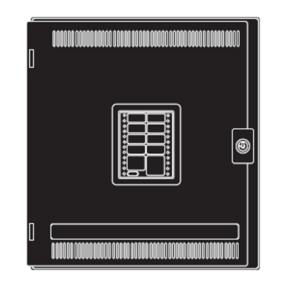
Page 72: Overview
Overview, Continued Overview LEDs and Keys The AutoPulse Z-10 user interface consists of LEDs and keys. It allows a system operator to monitor the status of the AutoPulse Z-10’s circuits. shows the operator interface for the Figure 5-1 AutoPulse Z-10. The LED labels used on the interface depend on whether the system is programmed as a preaction/deluge or agent release system. - Page 73 Overview, Continued Overview, Continued LEDs and Keys Table 5-1. AutoPulse Z-10 Operator Interface LEDs and Keys (continued) LED/Key Description Manual Release. Flashes to indicate that a manual release switch has been activated. Waterflow. If the sprinkler system is equipped with a...
-
Page 74: Delay Timers
Overview, Continued Overview, Continued LEDs and Keys Table 5-1. AutoPulse Z-10 Operator Interface LEDs and Keys (continued) LED/Key Description Pressing the ALARM SILENCE key provides a means of silencing the building’s audible notification appliances (horns). Alarm Silence Key and LED LED is ON to indicate that an alarm is still active in the system but the NACs have been silenced (i.e., the Alarm Silence Key... -
Page 75: Manual Release Switch
Overview, Continued Overview, Continued Manual Release For systems intended for Halon 1301(NFPA 12A), Halon 1211 (NFPA12B), or clean agent Switch (NFPA 2001) release, a pre-discharge NAC must be configured to warn building of the impending discharge. The setting of the release timer selects the duration of the pre-discharge signal. Compliance with ADA requires Audible and Visible notification. -
Page 76: Alarm Clear/Reset
Overview, Continued Overview, Continued Abort Switch Panel Indication for Abort Switch Active. Actuation of an abort switch during normal, non-alarm standby condition, or during an active, acknowledged alarm, will cause the “Abort Active” LED to flash and the sounder will sound steadily until ACK is pressed. After the ACK button is pressed, the “Abort Active”... -
Page 77: Acknowledging Alarms, Troubles, And Supervisory Conditions
Overview, Continued Acknowledging Alarms, Troubles, and Supervisory Conditions Panel Indications Table 5-2. Panel Responses for Alarm, Trouble, Supervisory Condition Panel Indications Condition Red LED, corresponding to zone or SPM in alarm, pulses. Tone-Alert Alarm sounds steady. Yellow LED, corresponding to zone or SPM with trouble condition, flashes. Trouble Tone-Alert pulses. -
Page 78: Silencing Alarms
Overview, Continued Silencing Alarms Procedure Silencing an Alarm turns off the horns and strobes that warn occupants of the building to the presence of an alarm condition. To silence an alarm, press the ALARM SILENCE key. The ALARM SILENCED LED turns on steady and the signals turn off. -
Page 79: Procedure
Overview, Continued Resetting the System Procedure 1. Restore or replace all affected devices (agent release tanks, sprinkler system components, smoke detectors, heat detectors, etc.) in accordance with the instructions provided with each device. 2. Press the SYSTEM RESET key. All outputs (NACs, RACs, and relays turn off) and zone power is dropped and restored. -
Page 80: Procedure
2. Place Program Switch on the AutoPulse Z-10 in the ON position. 3. Locate the PC within 6 feet of the AutoPulse Z-10 FACP and connect a Part No. 431206 serial cable to a free serial port (typically COM1) on the PC. -
Page 81: Appendix A Fm System Requirements
Overview, Continued Appendix A FM System Requirements Introduction This appendix lists specific requirements for Factory Mutual agent release and preaction/deluge systems. General Refer to Appendix C: Battery Selection Calculations to select the appropriate size of sealed lead-acid batteries for the required standby time. ... -
Page 82: Fm Requirements/Approvals
Overview, Continued FM Requirements/Approvals Automatic Release circuit voltages must remain between 20.4 and 26.4 VDC under all load conditions. Extinguishing Follow wiring chart to determine maximum wiring distance from panel to releasing appliances. Release Requirements Preaction/Deluge The RAC is compatible for use with any FM approved electric release deluge, pre-action and Applications refrigerated area sprinkler solenoid valve rated 22 watts or less. - Page 83 Overview, Continued Appendix B TEPG-US/Tyco Safety Products UL Part Number Cross Reference and Approved Valves Table B-1. UL Part Numbers Description TEPG Part No. Tyco Safety Products Part No. Internal Membrane Cover 636-598 431290 Membrane Keyswitch 637-599 431291 System Board...
- Page 84 637-806 433937 Maintenance Switch w/lamp Flush mount 637-804 433936 Table B-2. UL Approved Valves for Use With AutoPulse Z-10 NOTES AUTOMAN II-C Assembly (uses solenoid 17728; coil 25924) AUTOMAN II-C Explosion-Proof Releasing Device (uses solenoid 31492; coil 31438) AUTOMAN II-C Assembly (uses solenoid 68739; coil 25924) Solenoid Electric Actuator (uses solenoid 73111;...
- Page 85 Model D deluge valve, with solenoid 5550 Minimax Model MX1230 without diode, 24VDC, ½ in. NPT Burkert Model 5282 2/2-Way Solenoid Valve Versa Model CGS-4292-NB3-S20000 Tyco Safety Model TSP 304700001, 24V Products Model TSP 304205030, 24V Masteco Model MSC-01, 24V...
- Page 86 Overview, Continued Appendix C Battery Selection Calculations This appendix describes the method for selection of the properly sized sealed lead-acid battery for Introduction the required standby time. General Standby Current Main (System) Board: 100mA Each Relay Board: 20mA Note: Standby Current is the sum of all module currents, plus auxiliary 24V current. Alarm Current Main System Board: 140mA Each Relay Board: 70mA...
- Page 87 Overview, Continued Battery Selection Calculations Battery Selection 1. From previous calculations, locate total Standby Current (A) and convert to amperes. A = ________ (Note: amperes = mA ÷ 1000; µA ÷ 1,000,000; examples: 250 mA = 0.25 A; 1500 µA = 0.0015 A) 2.
- Page 88 Overview, Continued Battery Selection Calculations, Continued Battery Selection Table C-2. Determining Discharge Factor Discharge Discharge Discharge Discharge Discharge Discharge Discharge Discharge Factor Time Factor Time Factor Time Factor Time 0.083 hr 3.85 2 hr 1.43 8 hr 1.10 14 hr 1.03 0.166 hr 2.78...
- Page 89 Overview, Continued TYCO SAFETY PRODUCTS ONE STANTON STREET MARINETTE, WI 54143-2542 715-735-7411 Doc No. 430545 Part No. 579-357 Rev. U...
Need help?
Do you have a question about the AutoPulse Z-10 and is the answer not in the manual?
Questions and answers