Table of Contents
Advertisement
Quick Links
RAPID RESPONSE
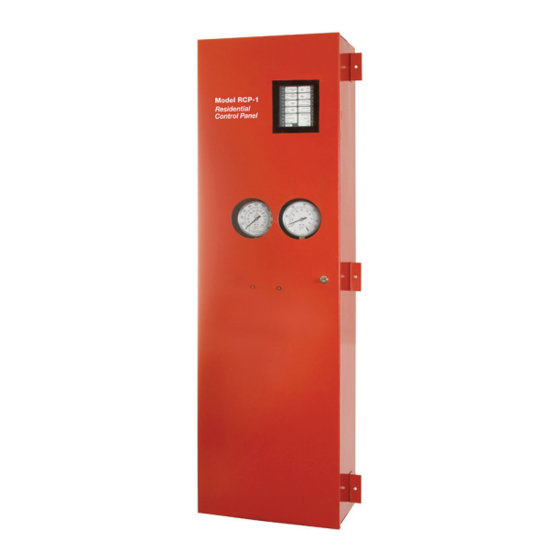
Model RCP-1 Residential Control Panel
1 or 1-1/2 Inch (DN25 or DN40), 175 psi (12,1 bar)
SECTIONS
General Description . . . . . . . . . . 1
Warnings . . . . . . . . . . . . . . . . . . . 2
Technical Data . . . . . . . . . . . . . . 2
Operation . . . . . . . . . . . . . . . . . . 3
Operator Interface . . . . . . . . . . . 6
Trouble Condition . . . . . . . . . . . . 7
In Case of Alarm Condition . . . . 7
System Resetting . . . . . . . . . . . . 7
Installation . . . . . . . . . . . . . . . . .10
Care and Maintenance . . . . . . .11
Ordering Procedure . . . . . . . . . .12
FIGURES, GRAPHS, AND
TABLES
Pressure Loss Graph . . . . . . . . . 3
Model RCP-1 Assembly . . . . . . . 4
Manifold Assembly . . . . . . . . . . 5
Operator Interface Card
(Front Side) . . . . . . . . . . . . . . . . . 6
Wiring Diagram . . . . . . . . . . . . . . 8
Off-Site Remote Relays . . . . . . . 9
On-Site Remote Signal . . . . . . . 9
Battery Harness . . . . . . . . . . . . .10
Operator Interface Card
(Back Side) . . . . . . . . . . . . . . . . .11
Page 1 of 12
General
Description
The TYCO RAPID RESPONSE Mod-
el RCP-1 Residential Control Panel is
an integrated valve manifold, air pres-
sure, and electronic control package
for controlling the release of water into
residential dry pipe sprinkler systems.
The Model RCP-1 Panel is intended for
use in one- and two- family dwellings
and mobile homes per NFPA 13D when
used with residential sprinklers that
have been listed for use in residential
dry pipe sprinkler systems.
The Model RCP-1 Panel incorporates
the Listed Model 4004R Household Fire
Warning Unit Subassembly installed
within the Model RCP-1 cabinet.
The Model RCP-1 Panel includes the
following features:
• Pre-wired assembly containing pre-
programmed control panel, system
performance gauges, and an en-
closed compressor
• Pre-engineered riser design
• Supervised system valve system
• Provision to trip test system without
having water flow into the system.
• High pressure supervision for indica-
tion of a false trip or failure of the au-
tomatic air supply cut-out switch
• Dry contacts for remote connection
(dial-up systems or additional moni-
toring, for example)
• 48-hour battery backup
JANUARY 2014
Worldwide
www.tyco-fire.com
Contacts
TFP480
Advertisement
Table of Contents

Related Manuals for Tyco RCP-1


Summary of Contents for Tyco RCP-1
-
Page 1: Table Of Contents
Pressure Loss Graph . . . . . . . . . 3 The Model RCP-1 Panel includes the Model RCP-1 Assembly . . . . . . . 4 following features: Manifold Assembly . -
Page 2: Warnings
Panel is UL Listed for use in res- Alarms. Notification Appliances idential dry pipe sprinkler systems The Model RCP-1 Panel will not oper- installed in one and two-family dwell- NFPA 13D does not require the instal- ate (that is, release water or energize... -
Page 3: Operation
Model sure of System Control Valve, or a pressed. RCP-1 Panel must be entered into the high system pressure condition re- program. The trip ratio for the Model • On alarm conditions, the tone-alert... -
Page 4: Model Rcp-1 Assembly
BRACKETS ENCLOSURE (PANEL DOOR NOT SHOWN) LEFT SIDE FRONT SYSTEM SYSTEM WATER SUPPLY DRAIN CONNECTION CONNECTION Nominal Weight: Always consult local jurisdictions for water 95 LBS. (43 kg) supply criteria and requirements. FIGURE 1 MODEL RCP-1 RESIDENTIAL CONTROL PANEL ASSEMBLY... -
Page 5: Manifold Assembly
PRESSURE GAUGE DRAIN VALVE (NORMALLY CLOSED) FLOW MAIN TEST VALVE CONTROL VALVE (NORMALLY (NORMALLY CLOSED) OPEN) WATER SUPPLY SYSTEM INLET CONNECTION (1 or 1-1/2 INCH NPT) DRAIN OUTLET CONNECTION (1/2 INCH NPT) FIGURE 2 MODEL RCP-1 RESIDENTIAL CONTROL MANIFOLD ASSEMBLY... -
Page 6: Operator Interface
Activation of the RAC cir- or normal status (for example, closed cuit energizes the Solenoid Valve to The Model RCP-1 Panel uses LEDs and valve position for Main Control Valve, permit water to enter the sprinkler KEYs as its primary means of display- closed valve position for System system piping. -
Page 7: In Case Of Supervisory
TFP480 Page 7 of 12 In Case of System KEYS • ACCEPT SIGNAL KEY Supervisory/ Resetting The system LEDs (ALARM, SUPER- VISORY, TROUBLE) flash to indi- Trouble cate the presence of an unaccepted Step 1. Use the ACCEPT SIGNAL KEY alarm, supervisory, or trouble condi- to accept every abnormal status pres- Condition... -
Page 8: Wiring Diagram
SELECT NORMALLY OPEN BATTERIES OR NORMALLY CLOSED RELAY #3 SELECT NORMALLY OPEN OR NORMALLY CLOSED 24 VDC CRIMPED ON CONNECTORS FIELD CONNECTED TWIST-ON WIRE CONNECTORS NYLON FIELD INSULATED GROUND WIRED RING FIGURE 4 MODEL RCP-1 RESIDENTIAL CONTROL PANEL ELECTRONIC CONTROL WIRING DIAGRAM... -
Page 9: Off-Site Remote Relays
TFP480 Page 9 of 12 JUMPER SELECTION OPTIONS NORMALLY CLOSED NORMALLY OPEN JUMPER LEFT JUMPER RIGHT RELAY #3 JUMPER JUMPERS TO SELECT NORMALLY OPEN OR RELAY #2 JUMPER CLOSED CONTACTS TROUBLE RELAY JUMPER TROUBLE RELAY (SELECT NORMALLY OPEN OR NORMALLY CLOSED) RELAY #2 (SELECT NORMALLY ALARM OPEN OR NORMALLY CLOSED) -
Page 10: Installation
In either case the Model for alarm state. LENCE KEY Accept the alarm condi- RCP-1 Panel must be located in an area tion by momentarily pressing the AC- not subject to freezing. • Maximum alarm current is 1A, and CEPT SIGNAL KEY. -
Page 11: Care And Maintenance
When the sys- Inspection/Test Procedure NAL KEY to scroll through MODES 1 tem trips (releases), completely open The Model RCP-1 Panel can be in- through 10 and verify that the POSI- the Drain Valve. spected and tested without having to TION 1 through 10 lights up as follows: • Note that the Operator Interface... -
Page 12: Ordering Procedure
Exercise care to ensure that all MODES Residential Control Panel, are restored to their proper settings. P/N 2656 GLOBAL HEADQUARTERS | 1400 Pennbrook Parkway, Lansdale, PA 19446 | Telephone +1-215-362-0700 Copyright © 2014 Tyco Fire Products, LP. All rights reserved.
Need help?
Do you have a question about the RCP-1 and is the answer not in the manual?
Questions and answers