Table of Contents
Advertisement
Quick Links
Advertisement
Table of Contents
Troubleshooting

Related Manuals for Yamaha TW200M 1999


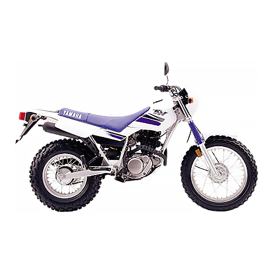
Summary of Contents for Yamaha TW200M 1999
- Page 1 OWNER’S MANUAL TW200M 3XT-28199-29...
- Page 3 EAU00000 INTRODUCTION Congratulations on your purchase of the Yamaha TW200. This model is the result of Yamaha’s vast experience in the production of fine sporting, touring, and pacesetting racing machines. It represents the high degree of craftsmanship and reliability that have made Yamaha a leader in these fields.
- Page 4 If there is any question concerning this manual, please consult your Yamaha dealer.
- Page 5 IMPORTANT MANUAL INFORMATION EW000002 PLEASE READ THIS MANUAL CAREFULLY AND COMPLETELY BEFORE OPERATING THIS MOTORCYCLE.
- Page 6 EAU00008 TW200M OWNER’S MANUAL ©1999 by Yamaha Motor Co., Ltd. 1st Edition, July 1999 All rights reserved. Any reprinting or unauthorized use without the written permission of Yamaha Motor Co., Ltd. is expressly prohibited. Printed in Japan.
-
Page 7: Table Of Contents
EAU00009 TABLE OF CONTENTS SAFETY INFORMATION ........1-1 Starter (choke) “1” .........3-8 Safe riding ............1-1 Kick starter ............3-8 Protective apparel ..........1-3 Steering lock.............3-9 Modification............1-3 Seat ..............3-9 Loading and accessories .........1-3 Helmet holder..........3-10 Gasoline and exhaust gas .......1-5 Rear shock absorber ........3-10 Location of the important labels.....1-7 Rear carrier .............3-11 Sidestand ............3-11... - Page 8 TABLE OF CONTENTS Cowling and panel removal and Brake and shift pedal lubrication ....6-24 installation ............6-6 Brake and clutch lever lubrication ....6-25 Cowling A ............6-6 Sidestand lubrication........6-25 Panel A ..............6-7 Rear suspension lubrication......6-25 Panel B ..............6-7 Front fork inspection........6-26 Spark plug............6-7 Steering inspection ........6-26 Engine oil ............6-9 Wheel bearings ..........6-27...
- Page 9 CONSUMER INFORMATION ......9-1 Identification number records......9-1 Key identification number .......9-1 Vehicle identification number ......9-1 Model label ............9-2 Noise regulation (For Australia)......9-2...
-
Page 10: Safety Information
EAU00017 Q SAFETY INFORMATION TWO-WHEELED MOTORCYCLES ARE SINGLE TRACK VEHICLES. THEIR SAFE USE AND OPER- ATION ARE DEPENDENT UPON THE USE OF PROPER RIDING TECHNIQUES AS WELL AS THE EXPERTISE OF THE OPERATOR. EVERY OPERATOR SHOULD KNOW THE FOLLOWING REQUIREMENTS BEFORE RIDING. HE OR SHE SHOULD: 1. - Page 11 Q SAFETY INFORMATION 4. Many accidents involve inexperienced operators. In fact, many operators who have been involved in accidents do not even have a current motorcycle license. a. Make sure you are qualified. Also, only lend your motorcycle to experienced operators. b.
-
Page 12: Protective Apparel
6. A passenger should also observe the above precautions. Modification Modifications made to the motorcycle not approved by Yamaha, or the removal of original equipment, may render your motorcycle unsafe for use and may cause severe personal injury. Modifications may also make your motorcycle illegal to use. - Page 13 Accessories Genuine Yamaha accessories have been specifically designed for use on this motorcycle. Since Yamaha cannot test all other accessories which may be available, you must personally be responsible for the proper selection, installation and use of non-Yamaha accessories. You should use extreme caution when selecting and installing any accessories.
-
Page 14: Gasoline And Exhaust Gas
Q SAFETY INFORMATION a. Accessories fitted to the handlebar or the front fork area can create instability due to improper weight distribution or aerodynamic changes. If accessories are added to the handlebar or front fork area, they must be as lightweight as possible and should be kept to a minimum. - Page 15 Q SAFETY INFORMATION a. The engine and exhaust system may be hot. Park the motorcycle in a place where pedestrians or children are not likely to touch these hot areas. b. Do not park the motorcycle on a slope or soft ground; the motorcycle may fall over. c.
-
Page 16: Location Of The Important Labels
Q SAFETY INFORMATION EAU02977 Location of the important labels Please read the following labels carefully before operating this motorcycle. - Page 17 Q SAFETY INFORMATION WARNING Before you operate this vehicle, read the owner’s manual. English 3HP-21568-00 4AA-22259-40...
-
Page 18: Description
EAU00026 DESCRIPTION Left view 2 3 4 5 1. Headlight (page 6-30) 6. Helmet holder (page 3-10) 2. Fuel cock (page 3-7) 7. Rear carrier (page 3-11) 3. Starter (choke) “1“ (page 3-8) 8. Shift pedal (page 3-4) 4. Air filter (page 6-12) 5. -
Page 19: Right View
DESCRIPTION Right view 9. Fuse (page 6-29) 10. Kick starter (page 3-8) 11. Rear brake pedal (page 3-5, 6-19) 12. Tool kit (page 6-1) -
Page 20: Controls/Instruments
DESCRIPTION Controls/Instruments 13. Clutch lever (page 3-4, 6-18) 18. Throttle grip (page 6-14, 6-24) 14. Left handlebar switches (page 3-3) 19. Fuel tank cap (page 3-5) 15. Speedometer (page 3-2) 20. Main switch (page 3-1) 16. Right handlebar switches (page 3-3) 17. -
Page 21: Instrument And Control Functions
EAU00027 INSTRUMENT AND CONTROL FUNCTIONS To lock the steering, turn the han- dlebars all the way to the left or right. With the key at “OFF”, push it into the main switch and release it, turn it counterclockwise to “LOCK” and remove it. To release the lock, turn the key to “OFF”. -
Page 22: Indicator Lights
INSTRUMENT AND CONTROL FUNCTIONS EAU00063 High beam indicator light “&” 1 2 3 This indicator comes on when the headlight high beam is used. 1. Turn indicator light “5” 1. Speedometer 2. High beam indicator light 2. Odometer “&” 3. Trip meter 3. -
Page 23: Handlebar Switches
INSTRUMENT AND CONTROL FUNCTIONS EAU00129 Horn switch “*” Press the switch to sound the horn. 1. Dimmer switch 1. Engine stop switch “ENGINE STOP” 2. Turn signal switch 2. Start switch “START” 3. Horn switch “*” EAU00137 Engine stop switch “ENGINE EAU00118 Handlebar switches... -
Page 24: Clutch Lever
INSTRUMENT AND CONTROL FUNCTIONS 1. Engine stop switch “ENGINE STOP” 1. Clutch lever 1. Shift pedal 2. Start switch “START” N. Neutral EAU00152 EAU00141 EAU00157 Clutch lever Shift pedal Start switch “START” The clutch lever is located on the starter motor cranks This motorcycle is equipped with a... -
Page 25: Front Brake Lever
INSTRUMENT AND CONTROL FUNCTIONS 1. Front brake lever 1. Rear brake pedal 1. Unlock 2. Open EAU00158 EAU00162 EAU00177 Front brake lever Rear brake pedal Fuel tank cap The front brake lever is located on The rear brake pedal is on the right To open the right handlebar. -
Page 26: Fuel
INSTRUMENT AND CONTROL FUNCTIONS EAU00185 NOTE: The tank cap cannot be reinstalled Always wipe off spilled fuel imme- unless it is unlocked. The key must diately with a dry and clean soft remain in the cap until the cap is cloth. -
Page 27: Fuel Cock
INSTRUMENT AND CONTROL FUNCTIONS EAU00192 Recommended fuel: Regular gasoline For Australia: Unleaded fuel only FUEL FUEL Fuel tank capacity: Total: 7.0 L Reserve: 1. Arrow mark 1. Arrow mark 1.0 L EAU01121 Fuel cock With the lever in this position, fuel The fuel cock supplies fuel from flows to the carburetor. -
Page 28: Starter (Choke) "1
INSTRUMENT AND CONTROL FUNCTIONS FUEL 1. Arrow mark 1. Starter (choke) “1” 1. Kick starter EAU02976 EAU00212 Starter (choke) “1” Kick starter This indicates reserve. If you run Starting a cold engine requires a Rotate the kick starter away from out of fuel while riding, move the richer air-fuel mixture. -
Page 29: Steering Lock
INSTRUMENT AND CONTROL FUNCTIONS To unlock the steering Insert the key, push it in and turn it 1/8 turn counterclockwise so that it moves out. Then, release and remove the key. 1. Steering lock 1. Bolt (×2) EAU02934 EAU01092 Steering lock Seat To lock the steering To remove the seat, remove the... -
Page 30: Helmet Holder
The helmet may hit cylinder in any way. Cylinder objects, causing loss of control damage will result in poor and possibly an accident. damping performance. 8 Take your shock absorber to a Yamaha dealer for any service. 3-10... -
Page 31: Rear Carrier
Please check carefully EW000032 the operating instructions listed below and if there is any indication Do not exceed the load limit of of a malfunction, return the motor- 3 kg. cycle to a Yamaha dealer immedi- ately for repair. 3-11... -
Page 32: Sidestand/Clutch Switch Operation Check
EW000045 TURN THE MAIN SWITCH TO “ON” AND THE ENGINE STOP SWITCH TO If improper operation is noted, “RUN”. consult a Yamaha dealer immedi- ately. TRANSMISSION IS IN GEAR AND SIDESTAND IS UP. PULL IN CLUTCH LEVER AND PUSH THE START SWITCH. -
Page 33: Pre-Operation Checks
EAU01114 PRE-OPERATION CHECKS Owners are personally responsible for their vehicle’s condition. Your motorcycle’s vital functions can start to deteriorate quickly and unexpectedly, even if it remains unused (for instance, if it is exposed to the elements). Any damage, fluid leak or loss of tire pressure could have serious consequences. Therefore, it is very important that, in addition to a thorough visual inspection, you check the following points before each ride. - Page 34 PRE-OPERATION CHECKS ITEM CHECKS PAGE 9 Check fuel level. Fuel tank 3-5 ~ 3-7 9 Fill with fuel if necessary. Lights, signals and 9 Check for proper operation. 6-30 ~ 6-31 switches 9 Check fluid level. Battery 6-27 ~ 6-29 9 Fill with distilled water if necessary.
-
Page 35: Operation And Important Riding Points
This motorcycle is equipped with a their functions. Consult starting and an ignition circuit cut- Yamaha dealer regarding any off switch. control or function that you do The engine can be started only not thoroughly understand. under one of the following condi-... - Page 36 OPERATION AND IMPORTANT RIDING POINTS TURN THE MAIN SWITCH TO “ON” AND THE ENGINE STOP SWITCH TO “RUN” IF TRANSMISSION IS IN NEUTRAL IF TRANSMISSION IS IN GEAR AND AND SIDESTAND IS DOWN, SIDESTAND IS UP, PUSH START SWITCH OR PULL IN CLUTCH LEVER AND PUSH START KICK THE KICK STARTER.
- Page 37 If the light does not come on, ask a Yamaha dealer to NOTE: inspect it. For maximum engine life, always warm up the engine before starting off.
-
Page 38: Starting A Warm Engine
OPERATION AND IMPORTANT RIDING POINTS EAU01258 EC000048 Starting a warm engine The starter (choke) is not required 8 Do not coast for long periods when the engine is warm. with the engine off, and do EC000046 not tow the motorcycle a long distance. -
Page 39: Tips For Reducing Fuel Consumption
OPERATION AND IMPORTANT RIDING POINTS EAU00424 EAU00436 EAU00446 Tips for reducing fuel Engine break-in 0 ~ 150 km consumption There is never a more important Avoid operation above 1/3 throttle. Your motorcycle’s fuel consump- period in the life of your motorcy- Stop the engine and let it cool for 5 tion depends to a large extent on cle than the period between zero... -
Page 40: Parking
Avoid prolonged full-throttle oper- ation. Vary speed occasionally. EC000049 FUEL If any engine trouble should occur during the break-in period, consult a Yamaha dealer immediately. 1. Arrow mark EAU00457 Parking When parking the motorcycle, stop the engine and remove the ignition key. -
Page 41: Periodic Maintenance And Minor Repair
If you are not familiar with motor- motorcycle in the safest and most cycle service, this work should be efficient condition possible. Safety done by a Yamaha dealer. is an obligation of the motorcycle owner. The maintenance and lubri- cation schedule chart should be... - Page 42 Yamaha dealer for service. EW000063 Modifications to this motorcycle not approved by Yamaha may cause loss of performance, and render it unsafe for use. Consult a Yamaha dealer before attempting any changes.
-
Page 43: Periodic Maintenance And Lubrication
PERIODIC MAINTENANCE AND MINOR REPAIR EAU00473 PERIODIC MAINTENANCE AND LUBRICATION Every Every 6,000 km 12,000 km INITIAL ITEM CHECKS AND MAINTENANCE JOBS (1,000 km) 6 months 12 months (Whichever (Whichever comes first) comes first) 9 Check fuel hoses for cracks or damage. √... - Page 44 PERIODIC MAINTENANCE AND MINOR REPAIR Every Every 6,000 km 12,000 km INITIAL ITEM CHECKS AND MAINTENANCE JOBS (1,000 km) 6 months 12 months (Whichever (Whichever comes first) comes first) 9 Check bearing for looseness or damage. √ √ 12 * Wheel bearings 9 Replace if necessary.
- Page 45 √ 9 Clean or replace if necessary. 25 * Engine oil strainer Since these items require special tools, data and technical skills, they should be serviced by a Yamaha dealer. EAU00479 NOTE: The air filter needs more frequent service if you are riding in unusually wet or dusty areas.
-
Page 46: Cowling And Panel Removal And Installation
PERIODIC MAINTENANCE AND MINOR REPAIR 1. Cowling A 1. Panel B 1. Screw 2. Panel A EAU01145 EAU01139 Cowling A Cowling and panel removal To remove and installation Remove the cowling screw and The cowlings and panels illustrated pull outward on the areas shown. need to be removed to perform some maintenance... -
Page 47: Panel A
PERIODIC MAINTENANCE AND MINOR REPAIR 1. Panel A 1. Panel B 1. Spark plug wrench 2. Screw (×2) EAU00494 EAU01833 EAU01345 Panel A Spark plug Panel B To remove Removal To remove Pull outward on the areas shown. 1. Remove the spark plug cap. Remove the screws and pull out- 2. - Page 48 Instead, take and, if necessary, adjust the the motorcycle to a Yamaha deal- 4. Install the spark plug cap. gap to specification. er. You should periodically remove and inspect the spark plug because...
-
Page 49: Engine Oil
PERIODIC MAINTENANCE AND MINOR REPAIR EAU00517 Engine oil Oil level measurement 1. Place the motorcycle on a level place and hold it in an upright position. Warm up the engine for several minutes. NOTE: Be sure the motorcycle is posi- 1. - Page 50 PERIODIC MAINTENANCE AND MINOR REPAIR 1. Drain plug 1. Drain plug 1. Filter cover screw (×2) 2. O-ring 2. Drain bolt 3. Remove the drain plug and 3. Compression spring 4. Remove the filter cover screws 4. Oil strainer drain bolt. and the oil filter cover.
- Page 51 PERIODIC MAINTENANCE AND MINOR REPAIR Tightening torque: Recommended oil: Drain plug: See page 8-1. 43 Nm (4.3 m0kg) Total amount: Filter cover screw: 1.3 L 7 Nm (0.7 m0kg) Periodic oil change: Drain bolt (filter cover): 1.0 L 10 Nm (1.0 m0kg) With oil filter replacement: 1.1 L 9.
-
Page 52: Air Filter
PERIODIC MAINTENANCE AND MINOR REPAIR 1. Screw (×4) 1. Air filter 2. Air filter case cover 3. Remove the air filter from its 5. Install the air filter in its case. EAU01094 Air filter case and clean it with solvent. 6. -
Page 53: Carburetor Adjustment
Most adjust- increase engine speed and in ments should be left to a Yamaha direction b to decrease engine dealer who has the professional speed. knowledge and experience to do so. However, the following may be... -
Page 54: Throttle Cable Free Play Inspection
To prevent this, the valve must be adjusted regularly. This clearance must be adjusted regu- adjustment, however, should be larly. This adjustment however, left to a professional Yamaha ser- should be left to a professional vice technician. Yamaha service technician. a. Free play... -
Page 55: Tires
PERIODIC MAINTENANCE AND MINOR REPAIR EAU00668 EW000087 Maximum load* 180 kg Tires Cold tire pressure Front Rear To ensure maximum performance, Proper loading of your motorcycle 125 kPa 125 kPa Up to 90 kg (1.25 kgf/cm , (1.25 kgf/cm long service, and safe operation, is important for several character- 1.25 bar) 1.25 bar) - Page 56 After extensive tests, the tires BRIDGESTONE 130/80-18 66P TW31 mentioned below have been REAR approved by Yamaha Motor Co., Manufacturer Size Type Ltd. for this model. No guarantee BRIDGESTONE 180/80-14M/C 78P TW34 for handling characteristics can be Minimum tire tread...
-
Page 57: Wheels
8 Always inspect the wheels have a Yamaha dealer replace before a ride. Check for cracks, the tire immediately. Brakes, bends warpage tires, and related wheel parts wheel. -
Page 58: Clutch Lever Free Play Adjustment
PERIODIC MAINTENANCE AND MINOR REPAIR 1. Locknut 1. Clutch cable 1. Adjusting bolt 2. Adjusting bolt 2. Adjusting nut 2. Locknut 3. Free play 3. Locknut 3. Free play EAU00694 EAU00699 If the specified free play cannot be Clutch lever free play Front brake lever free play obtained, proceed with the follow- adjustment... -
Page 59: Rear Brake Pedal Height And Free Play Adjustment
4. Loosen the locknut at the brake lever. EW000104 5. Turn the adjusting bolt at the brake lever in direction a to It is advisable to have a Yamaha loosen the cable. dealer make this adjustment. 6. Loosen the locknut at the brake hub. -
Page 60: Brake Light Switch Adjustment
8 If it is impossible to make Turn the adjusting nut in direction proper adjustment, consult a b to make the brake light come on Yamaha dealer. later. 6-20... -
Page 61: Checking The Brake Shoes
A wear indicator is provided on cator reaches to the wear limit line, without rider. each brake. This indicator allows ask a Yamaha dealer to replace the inspection of shoe wear without shoes. disassembling the brake. 6-21... -
Page 62: Drive Chain Slack Adjustment
PERIODIC MAINTENANCE AND MINOR REPAIR EC000096 Too little chain slack will overload the engine and other vital parts. Keep the slack within the specified limits. 5. After adjusting, be sure to tighten the axle nut to the a. Chain slack 1. -
Page 63: Drive Chain Lubrication
PERIODIC MAINTENANCE AND MINOR REPAIR EAU01106 7. Adjust the free play in the Drive chain lubrication brake pedal. (See page 6-19.) The chain consists of many parts which work with each other. If the EW000103 chain is not maintained properly, it will wear out quickly. -
Page 64: Cable Inspection And Lubrication
Lubricate the cables and cable with a suitable all-purpose grease. ends. If a cable does not operate smoothly, ask a Yamaha dealer to replace it. Recommended lubricant: Engine oil 6-24... -
Page 65: Brake And Clutch Lever Lubrication
Recommended lubricant: moves up and down smoothly. Engine oil Recommended lubricant: Engine oil EW000113 EAU00791 Rear suspension lubrication Lubricate the pivoting parts. If the sidestand does not move smoothly, consult a Yamaha deal- Recommended lubricant: Lithium soap base grease 6-25... -
Page 66: Front Fork Inspection
If any Check for scratches or damage on free play can be felt, ask a Yamaha the inner tube and excessive oil dealer to inspect and adjust the leakage from the front fork. -
Page 67: Wheel Bearings
If there is play in the front or rear Securely support the motorcycle wheel hub or if the wheel does not so there is no danger of it falling turn smoothly, have a Yamaha over. dealer inspect the wheel bearings. 1. Battery 2. - Page 68 PERIODIC MAINTENANCE AND MINOR REPAIR EW000116 EW000117 Battery electrolyte is poisonous Take care not to spill battery fluid and dangerous, causing severe on the chain. Battery fluid may burns, etc. It contains sulfuric acid. weaken the chain causing shorter Avoid contact with skin, eyes or chain life and possibly result in an clothing.
-
Page 69: Fuse Replacement
Install a new fuse of proper amperage. Turn on the switches and see if the electri- cal device operates. If the fuse immediately blows again, consult a Yamaha dealer. 6-29 6-29... -
Page 70: Headlight Bulb Replacement
6. Install the bulb holder cover, connector and headlight unit. 5. Put a new bulb into position 7. Install the cowling. and secure it in place with the 8. If the headlight beam adjust- bulb holder. ment necessary, Yamaha dealer to make that 6-30 adjustment. -
Page 71: Turn Signal Light Bulb Replacement
PERIODIC MAINTENANCE AND MINOR REPAIR 1. Screw (× 2) 1. Screw (× 2) 1. Bulb 2. Lense EAU01623 2. Remove the defective bulb by 3. Bulb Taillight bulb replacement pushing it inward and turning EAU01095 1. Remove the screws and the Turn signal light bulb it counterclockwise. -
Page 72: Supporting The Motorcycle
EAU01579 Rear wheel service Supporting the motorcycle Use a motorcycle stand or motor- Since the Yamaha TW200 has no cycle jack to elevate the motorcycle centerstand, follow these precau- so the rear wheel is off the ground. tions when removing the front and... -
Page 73: Front Wheel Installation
PERIODIC MAINTENANCE AND MINOR REPAIR 6. Install the speedometer cable and the clip. 7. Tighten the axle nut to the specified torque and install a new cotter pin. Tightening torque: Axle nut: 90 Nm (9.0 m0kg) 1. Brake cable free play adjusting nut 2. -
Page 74: Rear Wheel Removal
EW000122 motorcycle down. 4. Tighten the axle nut to the 8 It is advisable to have a specified torque and install the Yamaha dealer service the axle nut cotter pin. wheel. 8 Securely support the motorcy- Tightening torque: cle so there is no danger of it Axle nut: falling over. -
Page 75: Troubleshooting
(See page 6-19.) for making checks. If your motorcycle requires any EW000103 repair, bring it to a Yamaha dealer. skilled technicians Check the operation of the brake Yamaha dealership have the tools, light after adjusting the rear brake. -
Page 76: Troubleshooting Chart
2. Compression There is compression. Go to ignition check. Use the electric starter. No compression. Ask a Yamaha dealer to inspect. 3. Ignition Wipe clean with dry cloth and Open throttle half-way and start Wet. Remove spark correct spark gap or replace plug. -
Page 77: Motorcycle Care And Storage
EAU01518 MOTORCYCLE CARE AND STORAGE Before cleaning Cleaning Care 1. Cover up the muffler outlet After normal use The exposure of its technology with a plastic bag. Remove dirt with warm water, a makes a motorcycle charming but 2. Make sure that all caps and neutral detergent and a soft clean also vulnerable. - Page 78 MOTORCYCLE CARE AND STORAGE 8 Improper cleaning can damage 8 Do high-pressure After riding in the rain, near the windshields, cowlings, panels washers or steam-jet cleaners sea or on salt-sprayed roads and other plastic parts. Use since they cause water seep- Since sea salt or salt sprayed on only a soft, clean cloth or age and deterioration in the...
- Page 79 After cleaning 8. Let the motorcycle dry com- NOTE: 1. Dry the motorcycle with a pletely before storing it or cov- Consult Yamaha dealer chamois or an absorbing cloth. ering it. advice on what products to use. 2. Immediately drive...
-
Page 80: Storage
MOTORCYCLE CARE AND STORAGE Long-term a. Remove the spark plug cap Storage Before storing your motorcycle for and spark plug. Short-term several months: b. Pour a teaspoonful of engine Always store your motorcycle in a 1. Follow all the instructions in oil into the spark plug bore. - Page 81 MOTORCYCLE CARE AND STORAGE 6. Lubricate all control cables and 9. Remove the battery and fully the pivoting points of all levers charge it. Store it in a cool, dry and pedals as well as of the place and recharge it once a sidestand/centerstand.
-
Page 82: Specifications
EAU01038 SPECIFICATIONS Specifications Model TW200M Engine oil Dimensions Type –20° –10° 0° 10° 20° 30° 40° 50°C Overall length 2,090 mm SAE 10W/30 Overall width 910 mm SAE 10W/40 Overall height 1,115 mm SAE 15W/40 Seat height 790 mm SAE 20W/40 Wheel base 1,330 mm Ground clearance... - Page 83 SPECIFICATIONS Fuel Gear ratio 2.833 Type Regular gasoline 1.789 For Australia: 1.318 Unleaded fuel only 1.040 Fuel tank capacity 7.0 L 0.821 Reserve amount 1.0 L Chassis Carburetor Frame type Diamond Type/quantity Y24P-5A/1 Caster angle 26.3° Manufacturer TEIKEI Trail 94 mm Spark plug Tires Type/Manufacturer...
- Page 84 SPECIFICATIONS 80 kg load ~ Maximum Suspension load* Front Front 150 kPa (1.50 kgf/cm , 1.50 bar) Type Telescopic fork Rear 175 kPa (1.75 kgf/cm , 1.75 bar) Rear Off-road riding Type Swingarm Front 125 kPa (1.25 kgf/cm , 1.25 bar) (Monocross suspension) Rear 125 kPa (1.25 kgf/cm...
- Page 85 SPECIFICATIONS 12 V, 21W × 2 Front flasher light 12 V, 21W × 2 Rear flasher light 12 V, 3.4W × 1 Meter light 12 V, 3.4W × 1 Neutral indicator light 12 V, 3.4W × 1 High beam indicator light 12 V, 3.4W ×...
-
Page 86: How To Use The Conversion Table
SPECIFICATIONS EAU01064 HOW TO USE THE CONVERSION TABLE CONVERSION TABLE All specification data in this manual are listed in SI METRIC TO IMPERIAL and METRIC UNITS. Metric unit Multiplier Imperial unit Use this table to convert METRIC unit data to m •... - Page 87 Yamaha dealer or for reference in case the vehicle is stolen. 1. Key identification number 1. Vehicle identification number EAU01042...
- Page 88 Yamaha dealer. (b) The use of the vehicle after such device or element of design has been removed or rendered inoperative by any person.
- Page 90 PRINTED ON RECYCLED PAPER YAMAHA MOTOR CO., LTD. PRINTED IN JAPAN 2000·4–0.1×1(E)
Need help?
Do you have a question about the TW200M 1999 and is the answer not in the manual?
Questions and answers