Yamaha TW200 Owner's Manual
Hide thumbs
Also See for TW200:
- Service manual (276 pages) ,
- Owner's manual (106 pages) ,
- Service manual (277 pages)
Table of Contents
Advertisement
Advertisement
Table of Contents
Troubleshooting

Subscribe to Our Youtube Channel
Related Manuals for Yamaha TW200


Summary of Contents for Yamaha TW200
- Page 1 OWNER’S MANUAL TW200X TW200XC LIT-11626-21-33 10D-28199-11...
- Page 2 EAU10041...
- Page 3 Yamaha has met these standards without reducing the performance or economy of operation of the motorcycle. To maintain these high standards, it is important that you and your Yamaha dealer pay close attention to the...
-
Page 4: Important Manual Information
This manual should be considered a permanent part of this motorcycle and should remain with it even if the motorcycle is subsequently sold. Yamaha continually seeks advancements in product design and quality. Therefore, while this manual contains the most current product information available at the time of printing, there may be minor discrepancies between your motorcycle and this manual. - Page 5 IMPORTANT MANUAL INFORMATION EAU10192 AFFIX DEALER LABEL HERE TW200X/TW200XC OWNER’S MANUAL ©2007 by Yamaha Motor Corporation, U.S.A. 1st edition, April 2007 All rights reserved. Any reprinting or unauthorized use without the written permission of Yamaha Motor Corporation, U.S.A. is expressly prohibited.
-
Page 6: Table Of Contents
TABLE OF CONTENTS SAFETY INFORMATION ....1-1 PRE-OPERATION CHECKS ....4-1 Valve clearance ......6-17 Location of important labels .....1-5 Pre-operation check list ....4-2 Tires ..........6-17 Spoke wheels ....... 6-19 DESCRIPTION ........2-1 OPERATION AND IMPORTANT Accessories and replacement Left view ...........2-1 RIDING POINTS........ - Page 7 TABLE OF CONTENTS Lubricating the rear suspension ..6-29 YAMAHA MOTOR CORPORATION, Checking the front fork ....6-30 U.S.A. STREET AND ENDURO Checking the steering ....6-30 MOTORCYCLE LIMITED Checking the wheel bearings ..6-31 WARRANTY ........ 9-7 Battery ...........6-31 YAMAHA EXTENDED SERVICE Replacing the fuse ......6-34 (Y.E.S.) ........
-
Page 8: Safety Information
SAFETY INFORMATION EAU10311 TIONS. motorist’s blind spot. Many accidents involve inexperi- MOTORCYCLES SINGLE Safe riding enced operators. In fact, many op- TRACK VEHICLES. THEIR SAFE Always make pre-operation erators who have been involved in USE AND OPERATION ARE DEPEN- checks. Careful checks may help accidents do not even have a cur- DENT UPON THE USE OF PROPER prevent an accident. - Page 9 Modifications made to this motorcycle 180 kg (397 lb) (U49) juries. The use of a safety helmet is the not approved by Yamaha, or the re- single most critical factor in the preven- moval of original equipment, may ren- When loading within this weight limit,...
- Page 10 Cargo accessory weight stallation and use of non-Yamaha the motorcycle due to aerody- should be kept as low and close to accessories. Use extreme caution namic effects. Wind may at- the motorcycle as possible.
- Page 11 SAFETY INFORMATION Always turn the engine off when Do not park the motorcycle near refueling. a flammable source (e.g., a ker- Take care not to spill any gaso- osene heater, or near an open line on the engine or exhaust flame), otherwise it could catch system when refueling.
-
Page 12: Location Of Important Labels
SAFETY INFORMATION EAU10381 Location of important labels Please read the following important labels carefully before operating this vehicle. - Page 13 SAFETY INFORMATION WARNING WARNING BEFORE YOU OPERATE THIS VEHICLE, READ Improper loading can cause loss of control. THE OWNER’S MANUAL AND ALL LABELS. Read owner’s manual for proper loading. ALWAYS WEAR AN APPROVED MOTORCYCLE 3JJ—28446—A1 HELMET, eye protection, and protective clothing. 5GK-2118K-00 WARNING CAUTION...
-
Page 14: Description
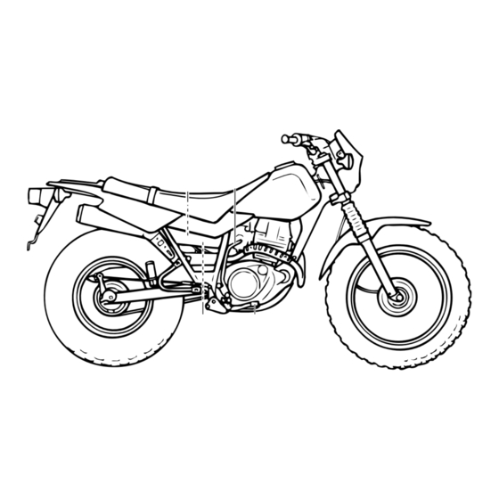
DESCRIPTION EAU10410 Left view 1. Fuel tank cap (page 3-5) 2. Fuel cock (page 3-7) 3. Helmet holder (page 3-9) 4. Luggage strap holder (page 3-10) 5. Drive chain slack adjusting plate (page 6-26) 6. Air filter element (page 6-14) 7. -
Page 15: Right View
DESCRIPTION EAU10420 Right view 1. Carrier (page 3-9) 2. Battery (page 6-31) 3. Engine oil level check window (page 6-11) 4. Brake pedal (page 3-5) 5. Owner’s tool kit (page 6-1) 6. Fuse (page 6-34) 7. Luggage strap holder (page 3-10) 8. -
Page 16: Controls And Instruments
DESCRIPTION EAU10430 Controls and instruments 1. Clutch lever (page 3-4) 9. Fuel tank cap (page 3-5) 2. Left handlebar switches (page 3-3) 3. Speedometer unit (page 3-2) 4. Main switch/steering lock (page 3-1) 5. Indicator lights (page 3-2) 6. Right handlebar switches (page 3-3) 7. -
Page 17: Instrument And Control Functions
INSTRUMENT AND CONTROL FUNCTIONS EAU10460 EAU10710 To unlock the steering Main switch/steering lock LOCK Insert the key and turn it to “OFF”. The steering is locked, and all electrical EWA10070 systems are off. The key can be re- WARNING moved. Never turn the key to “LOCK”... -
Page 18: Indicator Lights
INSTRUMENT AND CONTROL FUNCTIONS EAU10980 EAU11080 EAU11630 Indicator lights Speedometer unit High beam indicator light “ ” This indicator light comes on when the high beam of the headlight is switched 1. Speedometer 1. Turn signal indicator light “ ” 2. -
Page 19: Handlebar Switches
INSTRUMENT AND CONTROL FUNCTIONS EAU12347 Right EAU12500 Handlebar switches Horn switch “ ” Press this switch to sound the horn. Left EAU12660 Engine stop switch “ ” Set this switch to “ ” before starting the engine. Set this switch to “ ”... -
Page 20: Clutch Lever
INSTRUMENT AND CONTROL FUNCTIONS EAU12820 EAU12870 EAU12890 Clutch lever Shift pedal Brake lever 1. Clutch lever 1. Shift pedal 1. Brake lever The clutch lever is located at the left The shift pedal is located on the left The brake lever is located at the right handlebar grip. -
Page 21: Brake Pedal
INSTRUMENT AND CONTROL FUNCTIONS EAU12941 EAU32280 NOTE: Brake pedal Fuel tank cap The fuel tank cap cannot be installed unless the key is in the lock. In addition, the key cannot be removed if the cap is not properly installed and locked. EWA10120 WARNING Make sure that the fuel tank cap is... -
Page 22: Fuel
10%. Gasohol UNLEADED GASOLINE ONLY containing methanol is not recom- Fuel tank capacity: mended by Yamaha because it can 7.0 L (1.85 US gal) (1.54 Imp.gal) cause damage to the fuel system or ve- Fuel reserve amount: hicle performance problems. -
Page 23: Fuel Cock
INSTRUMENT AND CONTROL FUNCTIONS EAU13561 This indicates reserve. If you run out of Fuel cock fuel while riding, move the lever to this The fuel cock supplies fuel from the position. Fill the tank at the first oppor- tank to the carburetor while filtering it al- tunity. -
Page 24: Starter (Choke) Knob "1
INSTRUMENT AND CONTROL FUNCTIONS EAU13600 EAU13970 Starter (choke) knob “ ” Seat To remove the seat Remove the bolts, and then pull the seat off. 1. Projection 2. Seat holder 1. Starter (choke) knob “ ” 2. Place the seat in the original posi- tion, and then tighten the bolts. -
Page 25: Helmet Holder
Never ride with a helmet attached to will result in poor damping per- the helmet holder, since the helmet formance. may hit objects, causing loss of con- Always have a Yamaha dealer trol and possibly an accident. service the shock absorber. -
Page 26: Luggage Strap Holders
Yamaha’s ignition circuit cut-off system has been designed to assist the operator in fulfilling the respon- sibility of raising the sidestand be- fore starting off. Therefore, check this system regularly as described below and have a Yamaha dealer re- 3-10... -
Page 27: Ignition Circuit Cut-Off System
Periodically check the operation of the ignition circuit cut-off system according to the following procedure. EWA10250 WARNING If a malfunction is noted, have a Yamaha dealer check the system be- fore riding. 3-11... - Page 28 5. Push the start switch. Does the engine start? The neutral switch may be defective. The motorcycle should not be ridden until checked by a Yamaha dealer. With the engine still running: 6. Move the sidestand up. 7. Keep the clutch lever pulled.
-
Page 29: Pre-Operation Checks
PRE-OPERATION CHECKS EAU15593 The condition of a vehicle is the owner’s responsibility. Vital components can start to deteriorate quickly and unexpectedly, even if the vehicle remains unused (for example, as a result of exposure to the elements). Any damage, fluid leakage or loss of tire air pressure could have serious consequences. -
Page 30: Pre-Operation Check List
Adjust if necessary. Make sure that operation is smooth. Check cable free play. Throttle grip 6-16, 6-28 If necessary, have Yamaha dealer adjust cable free play and lubricate cable and grip housing. Make sure that operation is smooth. Control cables 6-28... - Page 31 Instruments, lights, signals Check operation. — and switches Correct if necessary. Check operation of ignition circuit cut-off system. Sidestand switch 3-10 If system is defective, have Yamaha dealer check vehicle. Check fluid level. Battery 6-31 Fill with distilled water if necessary.
-
Page 32: Operation And Important Riding Points
EAU15950 EAU32290 position, the neutral indicator light Starting and warming up a should be on, otherwise have a EWA10270 cold engine Yamaha dealer check the electrical cir- WARNING In order for the ignition circuit cut-off cuit. Become thoroughly familiar system to enable starting, one of the 4. -
Page 33: Starting A Warm Engine
OPERATION AND IMPORTANT RIDING POINTS EAU16640 EAU16671 NOTE: Starting a warm engine Shifting The engine is warm when it responds Follow the same procedure as for start- normally to the throttle with the starter ing a cold engine with the exception (choke) turned off. - Page 34 OPERATION AND IMPORTANT RIDING POINTS the neutral position, do not coast for long periods of time with the engine off, and do not tow the motorcycle for long dis- tances. The transmission is properly lubricated only when the engine is running. Inade- quate lubrication may damage the transmission.
-
Page 35: Engine Break-In
1600 km (1000 mi). The various parts in Yamaha dealer check the vehi- ans or children are not likely to the engine wear and polish themselves cle. -
Page 36: Periodic Maintenance And Minor Repair
TRAINED AND EQUIPPED TO PER- wrench may be necessary to perform FORM THESE PARTICULAR SER- certain maintenance work correctly. VICES. NOTE: If you do not have the tools or experi- ence required for a particular job, have a Yamaha dealer perform it for you. - Page 37 PERIODIC MAINTENANCE AND MINOR REPAIR EWA10340 WARNING Modifications approved Yamaha may cause loss of perfor- mance, excessive emissions, and render the vehicle unsafe for use. Consult a Yamaha dealer before at- tempting any changes.
-
Page 38: Periodic Maintenance Chart For The Emission Control System
Replace gasket(s) if necessary. Evaporative emis- Check control system for dam- √ √ sion control system age. (For California only) Replace if necessary. * Since these items require special tools, data and technical skills, have a Yamaha dealer perform the service. -
Page 39: General Maintenance And Lubrication Chart
PERIODIC MAINTENANCE AND MINOR REPAIR EAU32164 General maintenance and lubrication chart INITIAL ODOMETER READINGS 600 mi 4000 mi 7000 mi 10000 mi 13000 mi 16000 mi ITEM ROUTINE (1000 km) (6000 km) (11000 km) (16000 km) (21000 km) (26000 km) 1 month 6 months 12 months... - Page 40 Check chain slack, alignment and condition. Drive chain Adjust and thoroughly lubricate Every 300 mi (500 km) and after washing the motorcycle or riding in the rain chain with Yamaha chain and cable lube. Check bearing assemblies for looseness. Moderately repack with lith- √...
- Page 41 PERIODIC MAINTENANCE AND MINOR REPAIR INITIAL ODOMETER READINGS 600 mi 4000 mi 7000 mi 10000 mi 13000 mi 16000 mi ITEM ROUTINE (1000 km) (6000 km) (11000 km) (16000 km) (21000 km) (26000 km) 1 month 6 months 12 months 18 months 24 months 30 months...
- Page 42 Adjust headlight beam. * Since these items require special tools, data and technical skills, have a Yamaha dealer perform the service. NOTE: From 19000 mi (31000 km) or 36 months, repeat the maintenance intervals starting from 7000 mi (11000 km) or 12 months.
-
Page 43: Removing And Installing The Cowling And Panels
PERIODIC MAINTENANCE AND MINOR REPAIR EAU18721 To install the cowling Removing and installing the Place the cowling in the original posi- cowling and panels tion, and then install the screw. The cowling and panels shown need to be removed to perform some of the EAU32451 maintenance jobs described in this Panel A... -
Page 44: Checking The Spark Plug
PERIODIC MAINTENANCE AND MINOR REPAIR To install the panel EAU19603 Checking the spark plug Place the panel in the original position. The spark plug is an important engine component, which is easy to check. Since heat and deposits will cause any spark plug to slowly erode, the spark plug should be removed and checked in accordance with the periodic mainte-... - Page 45 Do not attempt to diagnose such problems yourself. In- Spark plug gap: 0.6–0.7 mm (0.024–0.028 in) stead, have a Yamaha dealer check the vehicle. 2. Clean the surface of the spark plug 2. Check the spark plug for electrode...
-
Page 46: Canister (For California Only)
PERIODIC MAINTENANCE AND MINOR REPAIR EAU19672 EAU19793 NOTE: Canister (for California only) Engine oil and oil filter The engine oil should be between the element minimum and maximum level marks. The engine oil level should be checked before each ride. In addition, the oil must be changed and the oil filter ele- ment cleaned at the intervals specified in the periodic maintenance and lubri-... - Page 47 PERIODIC MAINTENANCE AND MINOR REPAIR to collect the used oil. ECA11000 3. Remove the engine oil filler cap CAUTION: and drain bolt to drain the oil from When removing the engine oil drain the crankcase. bolt, O-ring, compression spring, and oil strainer will fall out. Take care not to lose these parts.
- Page 48 PERIODIC MAINTENANCE AND MINOR REPAIR 7. Check the O-ring for damage and addition, do not use oils labeled Tightening torque: replace it if necessary. “ENERGY CONSERVING II” or Engine oil drain bolt: 8. Clean the oil filter element with sol- higher.
-
Page 49: Cleaning The Air Filter Element And Check Hose
Recommended oil: wet or dusty areas. In addition, the air Yamaha foam air filter oil or other filter check hose must be frequently quality foam air filter oil checked and cleaned if necessary. -
Page 50: Cleaning The Spark Arrester
PERIODIC MAINTENANCE AND MINOR REPAIR To clean the air filter check hose EAU21234 Cleaning the spark arrester 1. Check the hose at the bottom of The spark arrester should be cleaned the air filter case for accumulated at the intervals specified in the periodic dirt or water. -
Page 51: Carburetor
1. Throttle cable free play The throttle cable free play should mea- sure 3.0–5.0 mm (0.12–0.20 in) at the throttle grip. Periodically check the throttle cable free play and, if neces- sary, have a Yamaha dealer adjust it. 6-16... -
Page 52: Valve Clearance
Rear: from occurring, the valve clearance the specified tires. 125 kPa (18 psi) (1.25 kgf/cm must be adjusted by a Yamaha dealer 90–179 kg (198–395 lb) (CAL) at the intervals specified in the periodic Tire air pressure 90–180 kg (198–397 lb) (U49): maintenance and lubrication chart. - Page 53 NEVER OVERLOAD nail or glass fragments in it, or if the Front tire: YOUR MOTORCYCLE. Make sure sidewall is cracked, have a Yamaha Size: the total weight of the cargo, rider, dealer replace the tire immediately. 130/80-18M/C 66P passenger, and accessories (fairing,...
-
Page 54: Spoke Wheels
If any dam- should be designed specifically for age is found, have a Yamaha this model, and they must be se- dealer replace the wheel. Do not curely mounted to maintain the in-... -
Page 55: Adjusting The Clutch Lever Free Play
PERIODIC MAINTENANCE AND MINOR REPAIR been approved by Yamaha. EAU22041 NOTE: Adjusting the clutch lever free If the specified clutch lever free play play could be obtained as described above, tighten the locknut and skip the rest of the procedure, otherwise proceed as follows. -
Page 56: Adjusting The Brake Lever Free Play
A soft or spongy feeling in the brake lever can indicate the presence of air in the hydraulic system. If there is air in the hy- draulic system, have a Yamaha dealer bleed the system before 1. Locknut operating the motorcycle. Air in 2. -
Page 57: Adjusting The Brake Pedal Position And Free Play
EWA10670 2. Adjusting bolt WARNING direction (a). To decrease the brake 3. Brake pedal position It is advisable to have a Yamaha pedal free play, turn the adjusting nut in 3. Tighten the locknut. dealer make these adjustments. direction (b). -
Page 58: Adjusting The Rear Brake Light Switch
If proper adjustment cannot be on just before braking takes effect. If obtained as described, have a necessary, adjust the brake light switch Yamaha dealer make this ad- 1. Brake pad wear indicator groove justment. as follows. Each front brake pad is provided with... -
Page 59: Checking The Front Brake Fluid Level
EAU32343 Checking the front brake fluid peared, have a Yamaha dealer replace level the brake pads as a set. Insufficient brake fluid may allow air to enter the brake system, possibly caus-... -
Page 60: Changing The Brake Fluid
EAU22720 Changing the brake fluid handlebars. Have a Yamaha dealer change the Use only the recommended quality brake fluid at the intervals specified in brake fluid, otherwise the rubber the NOTE after the periodic mainte- seals may deteriorate, causing nance and lubrication chart. -
Page 61: Drive Chain Slack
PERIODIC MAINTENANCE AND MINOR REPAIR EAU22760 Drive chain slack The drive chain slack should be checked before each ride and adjusted if necessary. EAU22773 To check the drive chain slack 1. Place the motorcycle on the side- stand. NOTE: 1. Drive chain slack 1. -
Page 62: Cleaning And Lubricating The Drive Chain
NOTE: brake light. For a thorough cleaning, have a Yamaha dealer remove the drive chain and soak it in solvent. 2. Spray Yamaha Chain and Cable Lube or a high-quality spray-type drive chain lubricant on both sides... -
Page 63: Checking And Lubricating The Cables
If a cable is damaged maintenance chart. or does not move smoothly, have a Yamaha dealer check or replace it. Recommended lubricant: Yamaha Chain and Cable Lube or engine oil SAE 10W-30... -
Page 64: Checking And Lubricating The Brake And Clutch Levers
Brake lever: WARNING Recommended lubricant: Silicone grease If the sidestand does not move up Lithium-soap-based grease Clutch lever: and down smoothly, have a Yamaha Lithium-soap-based grease (all-purpose grease) dealer check or repair it. Recommended lubricant: Lithium-soap-based grease (all-pur- pose grease) -
Page 65: Checking The Front Fork
Check the inner tubes for scratches, fork does not operate smoothly, Securely support the vehicle so that damage and excessive oil leakage. have a Yamaha dealer check or re- there is no danger of it falling over. pair it. To check the operation 2. -
Page 66: Checking The Wheel Bearings
Yamaha dealer check tervals specified in the periodic mainte- the wheel bearings. nance and lubrication chart. - Page 67 PERIODIC MAINTENANCE AND MINOR REPAIR of water. INTERNAL: Drink large quan- tities of water or milk and im- mediately call a physician. EYES: Flush with water for 15 minutes and seek prompt medical attention. Batteries produce explosive hy- drogen gas. Therefore, keep sparks, flames, cigarettes, etc., 1.
- Page 68 PERIODIC MAINTENANCE AND MINOR REPAIR tive (-) terminal. ages. 11. Install the seat. To store the battery 1. If the vehicle will not be used for more than one month, remove the battery, fully charge it, and then place it in a cool, dry place. 2.
-
Page 69: Replacing The Fuse
2. Remove the headlight unit by re- 4. If the fuse immediately blows 2. Remove the blown fuse, and then moving the bolts. again, have a Yamaha dealer install a new fuse of the specified check the electrical system. amperage. - Page 70 PERIODIC MAINTENANCE AND MINOR REPAIR and fingerprints on the headlight bulb using a cloth moistened with al- cohol or thinner. 1. Headlight coupler 1. Headlight bulb holder 2. Headlight bulb cover EWA10790 WARNING 4. Remove the headlight bulb holder by turning it counterclockwise, and Headlight bulbs get very hot.
-
Page 71: Replacing The Tail/Brake Light Bulb
1. Remove the tail/brake light lens by removing the screws. 8. Install the cowling. 1. Tail/brake light bulb 9. Have a Yamaha dealer adjust the 3. Insert a new bulb into the socket, headlight beam if necessary. push it in, and then turn it clock- wise until it stops. -
Page 72: Replacing A Turn Signal Light Bulb
PERIODIC MAINTENANCE AND MINOR REPAIR EAU24202 EAU24350 ECA11190 Replacing a turn signal light Supporting the motorcycle CAUTION: bulb Since this model is not equipped with a Do not overtighten the screw, other- centerstand, follow these precautions 1. Remove the turn signal light lens wise the lens may break. -
Page 73: Front Wheel
To remove the front wheel the wheel. EWA10820 ECA11070 WARNING CAUTION: It is advisable to have a Yamaha Do not apply the brake after the dealer service the wheel. wheel has been removed together Securely support the motorcy- with the brake disc, otherwise the cle so that there is no danger of brake pads will be forced shut. -
Page 74: Rear Wheel
EWA10820 ing the brake disc and that the slot in WARNING the speedometer gear unit fits over the It is advisable to have a Yamaha retainer on the fork leg. dealer service the wheel. Securely support the motorcy- cle so that there is no danger of it falling over. - Page 75 PERIODIC MAINTENANCE AND MINOR REPAIR EAU25761 fied torque. To install the rear wheel 1. Insert the wheel axle from the Tightening torque: Axle nut: left-hand side. 90 Nm (9.0 m·kgf, 65 ft·lbf) NOTE: Make sure that the drive chain adjust- 5.
-
Page 76: Troubleshooting
However, should your motorcycle require any repair, take it to a Yamaha dealer, whose skilled technicians have the necessary tools, experience, and know-how to service the motorcycle properly. -
Page 77: Troubleshooting Chart
Remove the spark plug and check the electrodes. The engine does not start. Have a Yamaha dealer check the vehicle. Check the battery. 4. Battery The engine turns over The battery is good. -
Page 78: Motorcycle Care And Storage
Be ble. Rust and corrosion can develop Cleaning sure to consult a Yamaha dealer for even if high-quality components are ECA10771 CAUTION: advice on what products to use be- used. - Page 79 MOTORCYCLE CARE AND STORAGE contact with strong or abrasive washing. ECA10790 cleaning products, solvent or CAUTION: thinner, fuel (gasoline), rust re- Do not use warm water since it in- After normal use movers or inhibitors, brake flu- creases the corrosive action of the Remove dirt with warm water, a mild id, antifreeze or electrolyte.
-
Page 80: Storage
7. Wax all painted surfaces. NOTE: dry place and, if necessary, protect it 8. Let the motorcycle dry completely Consult a Yamaha dealer for advice on against dust with a porous cover. before storing or covering it. what products to use. - Page 81 MOTORCYCLE CARE AND STORAGE “OFF”. install the spark plug and the than 0 °C (30 °F) or more than 3. Drain the carburetor float chamber spark plug cap. 30 °C (90 °F)]. For more informa- by loosening the drain bolt; this will EWA10950 tion on storing the battery, see WARNING...
-
Page 82: Specifications
SPECIFICATIONS EAU2633K Starting system: Carburetor: Electric starter Manufacturer: Lubrication system: Dimensions: TEIKEI Wet sump Type × quantity: Overall length: Engine oil: MV28 x 1 2090 mm (82.3 in) Type: Spark plug (s): Overall width: YAMALUBE 4, SAE10W30 or SAE20W40 820 mm (32.3 in) Manufacturer/model: Overall height: NGK/DR8EA... - Page 83 SPECIFICATIONS 3rd: Tire air pressure (measured on cold Rear brake: 29/22 (1.318) tires): Type: 4th: Drum brake Loading condition: 26/25 (1.040) Operation: 0–90 kg (0–198 lb) 5th: Right foot operation Front: 23/28 (0.821) Front suspension: 125 kPa (18 psi) (1.25 kgf/cm Chassis: Rear: Type:...
- Page 84 SPECIFICATIONS Bulb voltage, wattage × quantity: Headlight: 12 V, 60 W/55.0 W × 1 Tail/brake light: 12 V, 8.0 W/27.0 W × 1 Front turn signal/position light: 12 V, 27 W/8.0 W × 2 Rear turn signal light: 12 V, 27.0 W × 2 Meter lighting: 12 V, 3.4 W ×...
-
Page 85: Consumer Information
Record the key identification number, vehicle identification number and mod- el label information in the spaces pro- vided below for assistance when ordering spare parts from a Yamaha dealer or for reference in case the vehi- cle is stolen. KEY IDENTIFICATION NUMBER: 1. - Page 86 EAU26460 Model label 1. Model label The model label is affixed to the loca- tion shown. Record the information on this label in the space provided. This in- formation will be needed when ordering spare parts from a Yamaha dealer.
-
Page 87: Reporting Safety Defects
If you believe that your vehicle has a defect which could cause a crash or could cause injury or death, you should immediately inform the National Highway Traffic Safety Administration (NHTSA) in addition to notifying Yamaha Motor Corporation, U.S.A. If NHTSA receives similar complaints, it may open an investigation, and if it finds that a safety defect exists in a group of vehicles, it may order a recall and remedy campaign. -
Page 88: Motorcycle Noise Regulation
CONSUMER INFORMATION EAU26560 Motorcycle noise regulation TAMPERING WITH NOISE CONTROL SYSTEM PROHIBITED: Federal law prohibits the following acts or the causing thereof: (1) The removal or rendering inoperative by any person other than for purposes of maintenance, repair, or replacement of any device or element of design incorporated into any new ve- hicle for the purpose of noise control prior to its sale or delivery to the ultimate purchaser or while it is in use or (2) the use of the vehicle after such device or element of design has been removed or rendered inoperative by any person. -
Page 89: Maintenance Record
CONSUMER INFORMATION EAU26611 Maintenance record Copies of work orders and/or receipts for parts purchased and installed on your motorcycle will be required to document that maintenance has been completed in accordance with the emissions warranty. The chart below is printed only as a reminder that maintenance work is required. - Page 90 CONSUMER INFORMATION Maintenance Date of Servicing dealer Mileage Remarks interval service name and address 25000 mi (41000 km) or 48 months 28000 mi (46000 km) or 54 months 31000 mi (51000 km) or 60 months...
-
Page 91: Yamaha Motor Corporation, U.s.a. Street And Enduro Motorcycle Limited Warranty
CONSUMER INFORMATION EAU26663 YAMAHA MOTOR CORPORATION, U.S.A. STREET AND ENDURO MOTORCYCLE LIMITED WARRANTY Yamaha Motor Corporation, U.S.A. hereby warrants that CUSTOMER’S RESPONSIBILITY under this Engine new Yamaha motorcycles will be free from defects in warranty shall be to: Displacement Period... - Page 92 CUSTOMER SERVICE What costs are my responsibility during the warranty period? If your machine requires warranty service, you must take it to any authorized Yamaha The customer’s responsibility includes all costs of normal maintenance services, motorcycle dealer within the continental United States. Be sure to bring your warranty non-warranty repairs, accident and collision damages, and oil, oil filters, air filters, registration card or other valid proof of the original date of purchase.
-
Page 93: Yamaha Extended Service (Y.e.s.)
This excellent Y.E.S. plan coverage is only available to dealer to see how comforting uninterrupted factory- Yamaha owners like you, and only while your Yamaha is still backed protection can be. within the Yamaha Limited Warranty period. So visit your authorized Yamaha dealer to get all the facts. - Page 94 Yamaha Limited Warranty expires. A special note: If visiting your dealer isn’t convenient, contact Yamaha with your Primary ID number (your frame number). We’ll be happy to help you get the Y.E.S. coverage you need.
-
Page 95: Starting And Warming Up A Cold Engine
INDEX Accessories and replacement parts ..6-19 Engine break-in ......... 5-4 Neutral indicator light ........ 3-2 Air filter element and check hose, Engine oil and oil filter element ....6-11 Noise regulation ........9-4 cleaning ..........6-14 Engine, starting a warm......5-2 Engine stop switch ........ - Page 96 INDEX Tool kit ............6-1 Troubleshooting ........6-41 Troubleshooting chart ......6-42 Turn signal indicator light ......3-2 Turn signal light bulb, replacing ....6-37 Turn signal switch ........3-3 Valve clearance ........6-17 Vehicle identification number ....9-1 Warranty, extended........9-9 Warranty, limited ........
- Page 98 YAMAHA MOTOR CO., LTD. PRINTED ON RECYCLED PAPER PRINTED IN JAPAN 2007.5–0.4×1 !
Need help?
Do you have a question about the TW200 and is the answer not in the manual?
Questions and answers