Table of Contents
Advertisement
Quick Links
Advertisement
Table of Contents
Troubleshooting

Related Manuals for Yamaha XT250M 1999


Summary of Contents for Yamaha XT250M 1999
- Page 1 OWNER’S MANUAL XT250M 4FD-28199-27...
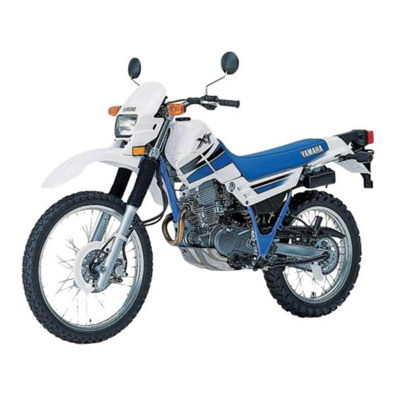
- Page 3 EAU00000 INTRODUCTION Congratulations on your purchase of the Yamaha XT250. This model is the result of Yamaha’s vast experience in the production of fine sporting, touring, and pacesetting racing machines. It represents the high degree of craftsmanship and reliability that have made Yamaha a leader in these fields.
- Page 4 If there is any question concerning this manual, please consult your Yamaha dealer.
- Page 5 IMPORTANT MANUAL INFORMATION EW000002 PLEASE READ THIS MANUAL CAREFULLY AND COMPLETELY BEFORE OPERATING THIS MOTORCYCLE.
- Page 6 EAU00008 XT250M OWNER’S MANUAL ©1999 by Yamaha Motor Co., Ltd. 1st Edition, June 1999 All rights reserved. Any reprinting or unauthorized use without the written permission of Yamaha Motor Co., Ltd. is expressly prohibited. Printed in Japan.
-
Page 7: Table Of Contents
EAU00009 TABLE OF CONTENTS SAFETY INFORMATION ........1-1 Seat ..............3-8 Safe riding ............1-1 Helmet holder...........3-9 Protective apparel ..........1-3 Rear shock absorber adjustment ....3-10 Modification............1-3 Sidestand ............3-12 Loading and accessories .........1-3 Sidestand/clutch switch operation check..3-12 Gasoline and exhaust gas .......1-5 Location of the important labels.....1-7 PRE-OPERATION CHECKS.........4-1 Pre-operation check list ........4-1 DESCRIPTION .............2-1... - Page 8 TABLE OF CONTENTS Air filter ............6-11 Battery.............6-28 Carburetor adjustment ........6-13 Fuse replacement...........6-29 Idle speed adjustment ........6-13 Headlight bulb replacement......6-29 Throttle cable free play adjustment....6-14 Turn signal light bulb replacement ....6-31 Valve clearance adjustment ......6-14 Taillight bulb replacement ......6-32 Tires..............6-15 Supporting the motorcycle ......6-32 Wheels ............6-16 Front wheel removal........6-33 Clutch lever free play adjustment....6-17...
-
Page 10: Safety Information
EAU00017 Q SAFETY INFORMATION TWO-WHEELED MOTORCYCLES ARE SINGLE TRACK VEHICLES. THEIR SAFE USE AND OPER- ATION ARE DEPENDENT UPON THE USE OF PROPER RIDING TECHNIQUES AS WELL AS THE EXPERTISE OF THE OPERATOR. EVERY OPERATOR SHOULD KNOW THE FOLLOWING REQUIREMENTS BEFORE RIDING. HE OR SHE SHOULD: 1. - Page 11 Q SAFETY INFORMATION 4. Many accidents involve inexperienced operators. In fact, many operators who have been involved in accidents do not even have a current motorcycle license. a. Make sure you are qualified. Also, only lend your motorcycle to experienced operators. b.
-
Page 12: Protective Apparel
6. A passenger should also observe the above precautions. Modification Modifications made to the motorcycle not approved by Yamaha, or the removal of original equipment, may render your motorcycle unsafe for use and may cause severe personal injury. Modifications may also make your motorcycle illegal to use. - Page 13 Accessories Genuine Yamaha accessories have been specifically designed for use on this motorcycle. Since Yamaha cannot test all other accessories which may be available, you must personally be responsible for the proper selection, installation and use of non-Yamaha accessories. You should use extreme caution when selecting and installing any accessories.
-
Page 14: Gasoline And Exhaust Gas
Q SAFETY INFORMATION a. Accessories fitted to the handlebar or the front fork area can create instability due to improper weight distribution or aerodynamic changes. If accessories are added to the handlebar or front fork area, they must be as lightweight as possible and should be kept to a minimum. - Page 15 Q SAFETY INFORMATION a. The engine and exhaust system may be hot. Park the motorcycle in a place where pedestrians or children are not likely to touch these hot areas. b. Do not park the motorcycle on a slope or soft ground; the motorcycle may fall over. c.
-
Page 16: Location Of The Important Labels
Q SAFETY INFORMATION EAU02977 Location of the important labels Please read the following labels carefully before operating this motorcycle. - Page 17 Q SAFETY INFORMATION WARNING Before you operate this vehicle, read the owner’s manual. English 3HP-21568-00 4AA-22259-40...
-
Page 18: Description
EAU00026 DESCRIPTION Left view 1. Front wheel (page 6-33) 6. Helmet holder (page 3-9) 2. Front turn signal light 7. Tool box (page 6-1) 3. Fuel cock (page 3-7) 8. Rear wheel (page 6-35) 4. Seat (page 3-8) 9. Shift pedal (page 3-4, 5-4) 5. -
Page 19: Right View
DESCRIPTION Right view 10. Tail/brake light (page 6-32) 11. Rear turn signal light (page 6-31) 12. Panel A (page 6-6) 13. Headlight (page 6-29) 14. Rear brake pedal (page 3-5) -
Page 20: Controls/Instruments
DESCRIPTION Controls/Instruments 15. Clutch lever (page 3-4, 6-17) 20. Front brake lever (page 3-5, 6-18) 16. Left handlebar switches (page 3-3) 21. Throttle grip (page 6-25) 17. Speedometer (page 3-2) 22. Fuel tank cap (page 3-5) 18. Main switch (page 3-1) 19. -
Page 21: Instrument And Control Functions
EAU00027 INSTRUMENT AND CONTROL FUNCTIONS EAU00038 OFF (Push) All electrical circuits are switched off. The key can be removed in this position. LOCK LOCK EAU00029 EAU00040 Main switch/Steering lock LOCK The main switch controls the igni- The steering is locked in this posi- tion and lighting systems. -
Page 22: Indicator Lights
INSTRUMENT AND CONTROL FUNCTIONS 1. Push 1. Turn indicator light “TURN” 1. Speedometer 2. Turn 2. High beam indicator light “HIGH BEAM” 2. Odometer 3. Neutral indicator light “NEUTRAL” 3. Trip odometer EW000016 4. Reset knob EAU00056 Indicator lights EAU00095 Speedometer Never turn the key to “OFF”... -
Page 23: Handlebar Switches
INSTRUMENT AND CONTROL FUNCTIONS EAU00127 Turn signal switch To signal a right-hand turn, push the switch to “6”. To signal a left- hand turn, push the switch to “4”. Once the switch is released it will return to the center position. To cancel the signal, push the switch in after it has returned to the center position. -
Page 24: Clutch Lever
INSTRUMENT AND CONTROL FUNCTIONS EAU00141 Start switch “START” starter motor cranks engine when pushing the start switch. EC000005 See starting instructions prior to starting the engine. 1. Clutch lever 1. Shift pedal EAU00152 Clutch lever EAU00157 Shift pedal The clutch lever is located on the This motorcycle is equipped with a left handlebar, and the ignition cir- constant-mesh 6-speed transmis-... -
Page 25: Front Brake Lever
INSTRUMENT AND CONTROL FUNCTIONS 1. Front brake lever 1. Rear brake pedal 1. Unlock 2. Open EAU00158 EAU00162 Front brake lever Rear brake pedal EAU00177 Fuel tank cap The front brake lever is located on The rear brake pedal is on the right To open the right handlebar. -
Page 26: Fuel
INSTRUMENT AND CONTROL FUNCTIONS EAU00185 NOTE: The tank cap cannot be reinstalled Always wipe off spilled fuel imme- unless it is unlocked. The key must diately with a dry and clean soft remain in the cap until the cap is cloth. -
Page 27: Fuel Cock
INSTRUMENT AND CONTROL FUNCTIONS EAU00192 Normal position Closed position Recommended fuel: Regular gasoline For Australia: Unleaded fuel only Fuel tank capacity: Total: 8.8 L Reserve: 1. Arrow mark over “OFF” 1. Arrow mark over “ON” 2.0 L EAU03050 Fuel cock With the lever in this position, fuel The fuel cock supplies fuel from flows to the carburetor. -
Page 28: Starter(Choke) "1
INSTRUMENT AND CONTROL FUNCTIONS Reserve position 1. Arrow mark over “RES” 1. Starter(choke) “1” 1. Panel A 2. Panel B EAU02976 EAU01648 Starter (choke) “1” Seat This indicates reserve. If you run Starting a cold engine requires a To remove out of fuel while riding, move the richer air-fuel mixture. -
Page 29: Helmet Holder
INSTRUMENT AND CONTROL FUNCTIONS 1. Bolt 1. Helmet holder 2. Unlock 2. Remove the seat bolts and lift To install EAU00261 Helmet holder the seat upward. 1. Insert the projections on the To open the helmet holder, insert front of the seat into the hold- the key in the lock and turn it as ers, then tighten the seat bolts. -
Page 30: Rear Shock Absorber Adjustment
INSTRUMENT AND CONTROL FUNCTIONS c. Tighten the locknut to the specified torque. Tightening torque: Locknut: 54 Nm (5.4 m0kg) EC000018 Always tighten the locknut against 1. Spring preload adjusting nut the spring adjusting nut and tight- 2. Locknut en the locknut to the specified EAU00303 Measurement “A”... - Page 31 8 Do not deform or damage the Maximum (hard): 1 click out* cylinder in any way. Cylinder *From the fully turned-in position damage will result in poor damping performance. 8 Take your shock absorber to a Yamaha dealer for any service. 3-11...
-
Page 32: Sidestand
PULL IN CLUTCH LEVER AND of a malfunction, return the motor- PUSH THE START SWITCH. cycle to a Yamaha dealer immedi- ately for repair. ENGINE WILL START. CLUTCH SWITCH IS OK. 3-12... - Page 33 INSTRUMENT AND CONTROL FUNCTIONS SIDESTAND IS DOWN. ENGINE WILL STALL. SIDESTAND SWITCH IS OK. EW000045 If improper operation is noted, consult a Yamaha dealer immedi- ately. 3-13...
-
Page 34: Pre-Operation Checks
EAU01114 PRE-OPERATION CHECKS Owners are personally responsible for their vehicle’s condition. Your motorcycle’s vital functions can start to deteriorate quickly and unexpectedly, even if it remains unused (for instance, if it is exposed to the elements). Any damage, fluid leak or loss of tire pressure could have serious consequences. Therefore, it is very important that, in addition to a thorough visual inspection, you check the following points before each ride. - Page 35 PRE-OPERATION CHECKS ITEM ROUTINE PAGE 9 Check for smooth operation. Brake and shift pedal 6-25 9 Lubricate if necessary. 9 Check for smooth operation. Brake and clutch lever pivot 6-25 9 Lubricate if necessary. 9 Check for smooth operation. Sidestand pivot 6-26 9 Lubricate if necessary.
-
Page 36: Operation And Important Riding Points
This motorcycle is equipped with their functions. Consult an ignition circuit cut-off system. Yamaha dealer regarding any The engine can be started only control or function that you do under one of the following condi- not thoroughly understand. tions: 8 Never start your engine or let 8 The transmission is in neutral. - Page 37 OPERATION AND IMPORTANT RIDING POINTS TURN THE MAIN SWITCH TO “ON” AND THE ENGINE STOP SWITCH TO “#”. IF TRANSMISSION IS IN NEUTRAL AND IF TRANSMISSION IS IN GEAR AND SIDESTAND IS DOWN, SIDESTAND IS UP, PULL IN CLUTCH LEVER AND PUSH PUSH START SWITCH.
- Page 38 NOTE: should be on. If the light does not The engine is warm when it 6. After starting the engine, move come on, ask a Yamaha dealer to responds normally to the throttle starter (choke) inspect it.
-
Page 39: Starting A Warm Engine
OPERATION AND IMPORTANT RIDING POINTS EAU01258 EC000048 Starting a warm engine The starter (choke) is not required 8 Do not coast for long periods when the engine is warm. with the engine off, and do EC000046 not tow the motorcycle a long distance. -
Page 40: Tips For Reducing Fuel Consumption
OPERATION AND IMPORTANT RIDING POINTS EAU00424 EAU00436 EAU00446 Tips for reducing fuel Engine break-in 0 ~ 150 km consumption There is never a more important Avoid operation above 1/3 throttle. Your motorcycle’s fuel consump- period in the life of your motorcy- Stop the engine and let it cool for 5 tion depends to a large extent on cle than the period between zero... -
Page 41: Parking
If any engine trouble should occur EW000058 during the break-in period, consult a Yamaha dealer immediately. The exhaust system is hot. Park the motorcycle in a place where pedestrians or children are not likely to touch the motorcycle. Do not park the motorcycle on a slope or soft ground;... -
Page 42: Periodic Maintenance And Minor Repair
If you are not familiar with motor- motorcycle in the safest and most cycle service, this work should be efficient condition possible. Safety done by a Yamaha dealer. is an obligation of the motorcycle owner. The maintenance and lubri- cation schedule chart should be... - Page 43 Yamaha dealer for service. EW000063 Modifications to this motorcycle not approved by Yamaha may cause loss of performance, and render it unsafe for use. Consult a Yamaha dealer before attempting any changes.
-
Page 44: Periodic Maintenance And Lubrication
PERIODIC MAINTENANCE AND MINOR REPAIR EAU00473 PERIODIC MAINTENANCE AND LUBRICATION EVERY 6,000 km 12,000 km Initial ITEM CHECKS AND MAINTENANCE JOBS (1,000 km) 6 months 12 months (Whichever (Whichever comes first) comes first) 9 Check fuel hoses for cracks or damage. √... - Page 45 PERIODIC MAINTENANCE AND MINOR REPAIR EVERY 6,000 km 12,000 km Initial ITEM CHECKS AND MAINTENANCE JOBS (1,000 km) 6 months 12 months (Whichever (Whichever comes first) comes first) 9 Check swingarm pivoting point for play. √ √ 9 Correct if necessary. 11 * Swingarm 9 Lubricate with molybdenum disulfide grease.
- Page 46 √ 9 Clean or replace if necessary. 23 * Engine oil strainer * Since these items require special tools, data and technical skills, they should be serviced by a Yamaha dealer. EAU02970* NOTE: 8 The air filter needs more frequent service if you are riding in unusually wet or dusty areas.
-
Page 47: Cowling A
PERIODIC MAINTENANCE AND MINOR REPAIR 1. Screw 1. Panel A 1. Panel B 2. Pull 2. Screw 2. Screw EAU00488 EAU01145 Panel A and B Cowling A To remove To remove Remove the screw and pull out- Remove the cowling screw and ward on the areas shown. -
Page 48: Spark Plug
The spark plug is an important problems yourself. Instead, take Removal engine component and is easy to the motorcycle to a Yamaha deal- 1. Remove the spark plug cap. inspect. The condition of the spark er. You should periodically remove 2. -
Page 49: Engine Oil
PERIODIC MAINTENANCE AND MINOR REPAIR EAU03002* Installation Engine oil 1. Measure the electrode gap Oil level inspection with a wire thickness gauge 1. Place the motorcycle on a level and, if necessary, adjust the place and hold it in an upright gap to specification. - Page 50 PERIODIC MAINTENANCE AND MINOR REPAIR 4 3 2 1 1. Engine oil filler cap 1. Engine oil drain bolt 2. O-ring Engine oil replacement and oil 3. Stop the engine. Place an oil 3. Compression spring 4. Oil strainer filter element cleaning pan under the engine and 4.
- Page 51 PERIODIC MAINTENANCE AND MINOR REPAIR EC000071* Before reinstalling the oil drain bolt, do not forget to install the O- ring, compression spring, and oil strainer in position. Tightening torque: Drain bolt: 1. Oil filter cover 1. Oil filter element 2. Drain bolt (filter cover) 2.
-
Page 52: Air Filter
PERIODIC MAINTENANCE AND MINOR REPAIR 10.Start the engine and warm it Recommended oil: up for a few minutes. While See page 8-1. warming up, check for oil leak- Oil quantity: age. If oil leakage is found, Total amount: stop the engine immediately 1.3 L and check for the cause. - Page 53 PERIODIC MAINTENANCE AND MINOR REPAIR EC000082 8 Make sure the air filter is prop- erly seated in the air filter case. 8 The engine should never be without filter installed. Excessive piston and/or cylinder wear 1. Air filter result. 3. Remove the air filter from the 5.
-
Page 54: Carburetor Adjustment
A diagnostic tachometer must be cated adjustment. Most adjust- used for this procedure. ments should be left to a Yamaha dealer who has the professional 1. Attach the tachometer. Start knowledge and experience to do the engine and warm it up for so. -
Page 55: Throttle Cable Free Play Adjustment
To prevent this, the valve clearance must be adjusted regu- larly. This adjustment however, should be left to a professional Yamaha service technician. 1. Locknut c. Free play 2. Adjusting nut 1. Loosen the locknut. -
Page 56: Tires
PERIODIC MAINTENANCE AND MINOR REPAIR EW000082 EW000083 Tire inflation pressure should be Proper loading of your motorcycle checked and adjusted when the is important for several character- temperature of the tire equals the istics of your motorcycle, such as ambient air temperature. Tire infla- handling, braking, performance... -
Page 57: Wheels
Yamaha dealer replace glass fragments in it, or if the side before a ride. Check for cracks, the tire immediately. Brakes, wall is cracked, contact a Yamaha bends warpage tires, and related wheel parts dealer immediately and have the wheel. -
Page 58: Clutch Lever Free Play Adjustment
PERIODIC MAINTENANCE AND MINOR REPAIR 8 Ride at moderate speeds after changing a tire since the tire surface must first be broken in for it to develop its optimal characteristics. 1. Locknut 1. Adjusting nut 2. Adjusting bolt 2. Locknut c. -
Page 59: Front Brake Lever Free Play Adjustment
The free play at the front brake and can result in loss of con- lever should be 2 ~ 5 mm. It is advisable to have a Yamaha trol and an accident. Have a 1. Loosen the locknut. dealer make this adjustment. -
Page 60: Free Play
1. Loosen the locknut. proper adjustment, consult a The rear brake pedal free play 2. Turn the adjusting bolt in Yamaha dealer. should be adjusted to 20 ~ 30 mm direction a to raise pedal at the brake pedal end. Turn the... -
Page 61: Brake Light Switch Adjustment
Front brake If the indicator reaches the wear vated by the brake pedal and is Apply the brake and inspect the limit line, ask a Yamaha dealer to properly adjusted when the brake wear indicator. replace the shoes. If the wear indicator is ALMOST in light comes on just before braking takes effect. -
Page 62: Inspecting The Brake Fluid Level
Always clean up spilled causing leakage poor fluid immediately. 8 Have a Yamaha dealer check brake performance. the cause if the brake fluid Recommended brake fluid: level goes down. DOT 4 1. Minimum level mark... -
Page 63: Brake Fluid Replacement
PERIODIC MAINTENANCE AND MINOR REPAIR EAU00742 Brake fluid replacement The brake fluid should be replaced only by trained Yamaha service personnel. Have the Yamaha deal- er replace the following compo- nents during periodic maintenance or when they are damaged or leak-... - Page 64 PERIODIC MAINTENANCE AND MINOR REPAIR EC000096 EW000103 Too little chain slack will overload Check the operation of the brake the engine and other vital parts. light after adjusting the rear brake. Keep the slack within the specified limits. 5. After adjusting, be sure to tighten the axle nut to the 1.
-
Page 65: Drive Chain Lubrication
If a cable does not operate Use only kerosene to clean the smoothly, ask a Yamaha dealer to drive chain. Wipe it dry, and thor- replace it. oughly lubricate it with SAE 30 ~ Recommended lubricant: 50W motor oil. -
Page 66: Throttle Cable And Grip Lubrication
PERIODIC MAINTENANCE AND MINOR REPAIR EAU00773 EAU02984 EAU02985 Throttle cable and grip Brake and shift pedal Brake and clutch lever lubrication lubrication lubrication The throttle twist grip assembly Lubricate the pivoting parts. Lubricate the pivoting parts. should be greased at the time that Recommended lubricant: Recommended lubricant: the cable is lubricated, since the... -
Page 67: Sidestand Lubrication
Rear suspension lubrication Front fork inspection Lubricate the pivoting parts. Visual check If the sidestand does not move smoothly, consult a Yamaha deal- EW000115 Recommended lubricant: Securely support the motorcycle Molybdenum disulfide grease so there is no danger of it falling over. -
Page 68: Steering Inspection
Hold the lower end of the front forks and try to move them forward and backward. If any free play can be felt, ask a Yamaha dealer to inspect and adjust the steering. Inspection is easier if the front wheel is removed. -
Page 69: Battery
8 If the battery seems to have ANTIDOTE: 8 Completely recharge the bat- discharged, consult a Yamaha 8 EXTERNAL: Flush with water. tery before storing. Storing a dealer. 8 INTERNAL: Drink large quanti- discharged battery can cause 8 If the motorcycle is equipped ties of water or milk. -
Page 70: Fuse Replacement
Install a new fuse of specified amperage. Turn on the switches and see if the elec- trical device operates. If the fuse immediately blows again, consult a Yamaha dealer. 6-29... - Page 71 PERIODIC MAINTENANCE AND MINOR REPAIR 1. Connector 1. Bulb holder 2. Bulb holder cover 2. Remove the headlight unit. 4. Turn the bulb holder counter- 3. Remove the connector and the clockwise to remove it and bulb holder cover. remove the defective bulb. EW000119 Keep flammable products and your hands away from a bulb while it is...
-
Page 72: Turn Signal Light Bulb Replacement
4. Install the lens and tighten the 7. Install the cowling. lens. screw. 8. If the headlight beam adjust- 2. Remove the defective bulb by ment necessary, pushing it inward and turning Yamaha dealer to make that it counterclockwise. adjustment. 6-31... -
Page 73: Taillight Bulb Replacement
PERIODIC MAINTENANCE AND MINOR REPAIR EAU01579 Supporting the motorcycle Since the Yamaha XT250 has no centerstand, follow these precau- tions when removing the front and rear wheel or performing other maintenance requiring the motor- cycle to stand upright. Check that... -
Page 74: Front Wheel Removal
Front wheel removal when the disc and caliper are sepa- rated. EW000122 8 It is advisable to have a Yamaha dealer service the wheel. 8 Securely support the motorcy- cle so there is no danger of it falling over. 1. Remove the engine guard. -
Page 75: Front Wheel Installation
PERIODIC MAINTENANCE AND MINOR REPAIR Tightening torque: Axle nut: 85 Nm (8.5 m0kg) 5. Install the speedometer cable. 6. Install a new cotter pin. EW000124 Always use a new cotter pin. EAU01449 2. Lift up the wheel between the Front wheel installation 7. -
Page 76: Rear Wheel Removal
8 It is advisable to have a ing a suitable stand under the outward and the slot in the Yamaha dealer service the engine. brake shoe plate is fit over the wheel. 5. Remove the axle nut. -
Page 77: Troubleshooting
EW000110 describes a quick, easy procedure for making checks. If your motorcycle requires any Always use a new cotter pin on repair, bring it to a Yamaha dealer. the axle nut. skilled technicians Yamaha dealership have the tools, 5. Insert the brake rod into the... -
Page 78: Troubleshooting Chart
2. Compression There is compression. Go to ignition check. Use the electric starter. No compression. Ask a Yamaha dealer to inspect. 3. Ignition Wipe clean with dry cloth and correct Open throttle half-way and start Wet. Remove spark spark gap or replace spark plug. -
Page 79: Motorcycle Care And Storage
EAU01518 MOTORCYCLE CARE AND STORAGE Before cleaning Cleaning Care 1. Cover up the muffler outlet After normal use The exposure of its technology with a plastic bag. Remove dirt with warm water, a makes a motorcycle charming but 2. Make sure that all caps and neutral detergent and a soft clean also vulnerable. - Page 80 MOTORCYCLE CARE AND STORAGE 8 Improper cleaning can damage 8 Do high-pressure After riding in the rain, near the windshields, cowlings, panels washers or steam-jet cleaners sea or on salt-sprayed roads and other plastic parts. Use since they cause water seep- Since sea salt or salt sprayed on only a soft, clean cloth or age and deterioration in the...
- Page 81 EWA00001 After cleaning NOTE: 1. Dry the motorcycle with a Consult Yamaha dealer Make sure that there is no oil or chamois or an absorbing cloth. advice on what products to use. wax on the brakes and tires. If nec- 2.
-
Page 82: Storage
MOTORCYCLE CARE AND STORAGE Long-term c. Install the spark plug cap onto Storage Before storing your motorcycle for the spark plug and place the Short-term several months: spark plug on the cylinder Always store your motorcycle in a 1. Follow all the instructions in head so that the electrodes are cool, dry place and, if necessary, the “Care”... - Page 83 MOTORCYCLE CARE AND STORAGE 7. Check and, if necessary, cor- NOTE: rect the tire air pressure, then Make any necessary repairs before raise the motorcycle so that storing the motorcycle. both of its wheels are off the ground. Alternatively, turn the wheels a little every month in order to prevent the tires from becoming degraded in one...
-
Page 84: Specifications
EAU01038 SPECIFICATIONS Specifications Model XT250 Engine oil Dimensions Type –20° –10° 0° 10° 20° 30° 40° 50°C Overall length 2,070 mm SAE 10W/30 Overall width 800 mm SAE 10W/40 Overall height 1,160 mm SAE 15W/40 Seat height 810 mm SAE 20W/40 Wheelbase 1,350 mm Ground clearance... - Page 85 SPECIFICATIONS Air filter Wet type element Gear ratio 3.090 Fuel 2.000 Type Regular gasoline 1.428 Unleaded fuel only (for Australia) 1.125 Fuel tank capacity 8.8 L 0.925 Reserve amount 2.0 L 0.793 Carburetor Chassis Type × quantity BST34 × 1 Frame type Diamond Manufacturer...
- Page 86 SPECIFICATIONS Air pressure (cold tire) Suspension Up to 90 kg load* Front Front 125 kPa; 1.25 kgf/cm ; 1.25 bar Type Telescopic fork Rear 150 kPa; 1.50 kgf/cm ; 1.50 bar Rear 90 kg load ~ maximum load* Type Swingarm (link suspension) Front 150 kPa;...
- Page 87 SPECIFICATIONS Bulb voltage, wattage × quantity 12V, 35W / 35W × 1 Headlight 12V, 5W / 21W × 1 Tail / brake light 12V, 21W × 4 Turn signal light 12V, 3.4W × 1 Meter light 12V, 3.4W × 1 Neutral indicator light 12V, 3.4W ×...
-
Page 88: How To Use The Conversion Table
SPECIFICATIONS EAU01064 HOW TO USE THE CONVERSION TABLE CONVERSION TABLE All specification data in this manual are listed in SI METRIC TO IMPERIAL and METRIC UNITS. Metric unit Multiplier Imperial unit Use this table to convert METRIC unit data to m •... -
Page 89: Consumer Information
Yamaha dealer or for reference in case the vehicle is stolen. 1. Key identification number 1. Vehicle identification number EAU01042... -
Page 90: Model Label
(b) The use of the vehicle after Yamaha dealer. such device or element of design has been removed or rendered inoperative by any person. - Page 92 YAMAHA MOTOR CO., LTD. PRINTED ON RECYCLED PAPER PRINTED IN JAPAN 99· 6–0.2×1(E)
Need help?
Do you have a question about the XT250M 1999 and is the answer not in the manual?
Questions and answers