
Related Manuals for Yamaha XT250Z


Summary of Contents for Yamaha XT250Z
- Page 1 Read this manual carefully before operating this vehicle. OWNER’S MANUAL XT250Z XT250ZC LIT-11626-23-37 3C5-28199-12...
- Page 2 EAU10042 Read this manual carefully before operating this vehicle. This manual should stay with this vehicle if it is sold.
- Page 3 Yamaha has met these standards without reducing the performance or economy of operation of the motorcycle. To maintain these high standards, it is important that you and your Yamaha dealer pay close attention to the recommended maintenance schedules and operating instructions contained within this manual.
-
Page 4: Important Manual Information
IMPORTANT MANUAL INFORMATION EAU10132 Particularly important information is distinguished in this manual by the following notations: This is the safety alert symbol. It is used to alert you to potential personal injury hazards. Obey all safety messages that follow this symbol to avoid possible injury or death. - Page 5 IMPORTANT MANUAL INFORMATION EAU10193 XT250Z/XT250ZC OWNER’S MANUAL ©2009 by Yamaha Motor Corporation, U.S.A. 1st edition, April 2009 All rights reserved. Any reprinting or unauthorized use without the written permission of Yamaha Motor Corporation, U.S.A. is expressly prohibited. Printed in Japan.
-
Page 6: Table Of Contents
TABLE OF CONTENTS LOCATION OF IMPORTANT FOR YOUR SAFETY – Checking the throttle cable free LABELS ..........1-1 PRE-OPERATION CHECKS .... 5-1 play ........... 7-18 Valve clearance ......7-19 SAFETY INFORMATION ....2-1 OPERATION AND IMPORTANT Tires ..........7-19 RIDING POINTS......... 6-1 Spoke wheels ...... - Page 7 Replacing the fuse ......7-32 MOTORCYCLE LIMITED Replacing the headlight bulb ..7-33 WARRANTY ......10-7 Replacing the tail/brake light YAMAHA EXTENDED SERVICE bulb ........... 7-34 (Y.E.S.) ........10-10 Replacing a turn signal light bulb ........... 7-35 Supporting the motorcycle .... 7-35 Front wheel ........
-
Page 8: Location Of Important Labels
Read and understand all of the labels on your vehicle. They contain important information for safe and proper operation of your vehicle. Never remove any labels from your vehicle. If a label becomes difficult to read or comes off, a replacement label is available from your Yamaha dealer. - Page 9 LOCATION OF IMPORTANT LABELS 1 California only CARB. Cold tire normal pressure should be set FROM as follows. FUEL TANK Up to 90 kg (198 Ibs) load FRONT : 125 kPa, ( 1.25 kgf / cm ), 18 psi REAR : 150 kPa, ( 1.50 kgf / cm ), 22 psi 90 kg (198 Ibs)
- Page 10 LOCATION OF IMPORTANT LABELS...
- Page 11 LOCATION OF IMPORTANT LABELS...
-
Page 12: Safety Information
SAFETY INFORMATION EAU10313 time you use the vehicle to make sure it motorist’s blind spot. is in safe operating condition. Failure to Many accidents involve inexperi- Be a Responsible Owner inspect or maintain the vehicle properly enced operators. In fact, many op- As the vehicle’s owner, you are respon- increases the possibility of an accident erators who have been involved in... - Page 13 SAFETY INFORMATION ed by road and traffic conditions. tion or reduction of head injuries. sion, and eventually death. Always signal before turning or Always wear an approved helmet. Carbon Monoxide is a colorless, odor- changing lanes. Make sure that Wear a face shield or goggles. less, tasteless gas which may be other motorists can see you.
- Page 14 Yamaha accessories, which are avail- of the motorcycle is changed. To avoid to minimize imbalance or instabili- able only from a Yamaha dealer, have the possibility of an accident, use ex- been designed, tested, and approved treme caution when adding cargo or Shifting weights can create a sud- by Yamaha for use on your vehicle.
-
Page 15: Specifications
SAFETY INFORMATION or others. Installing aftermarket prod- lightweight as possible and Aftermarket Tires and Rims ucts or having other modifications per- should be kept to a minimum. The tires and rims that came with your formed to your vehicle that change any Bulky or large accessories may motorcycle were designed to match the of the vehicle’s design or operation... -
Page 16: Description
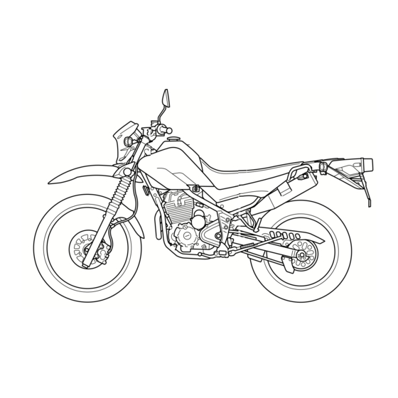
DESCRIPTION EAU10410 Left view 1. Fuel cock (page 4-8) 2. Starter (choke) knob (page 4-9) 3. Air filter element (page 7-16) 4. Helmet holder (page 4-10) -
Page 17: Right View
DESCRIPTION EAU10420 Right view 1. Spark arrester (page 7-17) 2. Battery (page 7-31) 3. Fuse (page 7-32) 4. Owner’s tool kit (page 7-2) 5. Engine oil level check window (page 7-13) 6. Engine oil filler bolt (page 7-13) -
Page 18: Controls And Instruments
DESCRIPTION EAU10430 Controls and instruments 1. Clutch lever (page 4-5) 8. Throttle grip (page 7-18) 2. Left handlebar switches (page 4-4) 9. Fuel tank cap (page 4-6) 3. Indicator lights (page 4-2) 4. Main switch/steering lock (page 4-1) 5. Multi-function display (page 4-3) 6. -
Page 19: Instrument And Control Functions
INSTRUMENT AND CONTROL FUNCTIONS EAU10460 the engine stalls. To lock the steering Main switch/steering lock EAU10661 All electrical systems are off. The key can be removed. EWA10061 WARNING Never turn the key to “OFF” or “LOCK” while the vehicle is moving. Otherwise the electrical systems will 1. -
Page 20: Indicator Lights
INSTRUMENT AND CONTROL FUNCTIONS To unlock the steering EAU10981 EAU11080 Indicator lights High beam indicator light “ ” This indicator light comes on when the high beam of the headlight is switched 1. Push. 1. High beam indicator light “ ”... -
Page 21: Multi-Function Display
INSTRUMENT AND CONTROL FUNCTIONS EAU44862 multi-function display will appear Multi-function display one after the other and then disap- EWA12312 pear, in order to test the electrical WARNING circuit. Be sure to stop the vehicle before To switch the speedometer and making any setting changes to the odometer/tripmeter displays be- multi-function... -
Page 22: Handlebar Switches
INSTRUMENT AND CONTROL FUNCTIONS Clock mode EAU12348 Right Handlebar switches To set the clock: Left 1. Push the “SELECT” button and “RESET” button together for at least two seconds. 2. When the hour digits start flashing, push the “RESET” button to set the hours. -
Page 23: Clutch Lever
INSTRUMENT AND CONTROL FUNCTIONS EAU12500 EAU12820 EAU12870 Clutch lever Shift pedal Horn switch “ ” Press this switch to sound the horn. EAU12660 Engine stop switch “ ” Set this switch to “ ” before starting the engine. Set this switch to “ ”... -
Page 24: Brake Lever
INSTRUMENT AND CONTROL FUNCTIONS EAU12890 EAU12941 EAUM1793 Brake lever Brake pedal Fuel tank cap To remove the fuel tank cap 1. Open the fuel tank cap lock cover. 2. Insert the key into the lock and turn it 1/4 turn clockwise. The lock will be released and the fuel tank cap can be removed. -
Page 25: Fuel
INSTRUMENT AND CONTROL FUNCTIONS EAU13212 Fuel Make sure there is sufficient gasoline in the tank. EWA10881 WARNING Gasoline and gasoline vapors are extremely flammable. To avoid fires and explosions and to reduce the risk of injury when refueling, follow these instructions. 1. -
Page 26: Fuel Cock
Your Yamaha engine has been de- signed to use regular unleaded gaso- line with a pump octane number [(R+M)/2] of 86 or higher, or a research... -
Page 27: Starter (Choke) Knob
INSTRUMENT AND CONTROL FUNCTIONS This indicates reserve. If you run out of EAU13600 Starter (choke) knob “ ” fuel while riding, move the lever to this position. Fill the tank at the first oppor- tunity. Be sure to set the lever back to “ON”... -
Page 28: Seat
INSTRUMENT AND CONTROL FUNCTIONS EAU13970 EAU14282 Seat Helmet holder To remove the seat Remove the bolts, and then pull the seat off. 1. Projection 2. Seat holder 1. Helmet holder 2. Place the seat in the original posi- 2. Unlock. tion, and then tighten the bolts. -
Page 29: Adjusting The Shock Absorber Assembly
Maximum (hard): ing ring. Distance A = 187 mm (7.36 in) It is recommended to have a Yamaha dealer adjust the spring preload. How- 3. Tighten the locknut to the specified ever, if you choose to make this adjust- torque. -
Page 30: Sidestand
Yamaha’s ignition circuit cut-off system has been designed to assist the operator in fulfilling the respon- sibility of raising the sidestand be- fore starting off. Therefore, check this system regularly as described below and have a Yamaha dealer re- 4-12... -
Page 31: Ignition Circuit Cut-Off System
INSTRUMENT AND CONTROL FUNCTIONS EAU15314 Ignition circuit cut-off system The ignition circuit cut-off system (com- prising the sidestand switch, clutch switch and neutral switch) has the fol- lowing functions. It prevents starting when the trans- mission is in gear and the side- stand is up, but the clutch lever is not pulled. - Page 32 INSTRUMENT AND CONTROL FUNCTIONS WARNING With the engine turned off: 1. Move the sidestand down. If a malfunction is noted, have a Yamaha 2. Make sure that the engine stop switch is set to “ ”. dealer check the system before riding.
-
Page 33: For Your Safety - Pre-Operation Checks
Failure to inspect or maintain the vehicle properly increases the possibility of an accident or equipment damage. Do not operate the vehicle if you find any problem. If a problem cannot be corrected by the procedures provided in this manual, have the vehicle inspected by a Yamaha dealer. Before using this vehicle, check the following points:... - Page 34 Adjust if necessary. Make sure that operation is smooth. Check cable free play. Throttle grip 7-18, 7-27 If necessary, have Yamaha dealer adjust cable free play and lubricate cable and grip housing. Make sure that operation is smooth. Control cables 7-27 Lubricate if necessary.
-
Page 35: Operation And Important Riding Points
(choke) on on. If not, ask a Yamaha dealer to longer than necessary. The time nec- check the electrical circuit. essary for starter (choke) use depends 4. -
Page 36: Starting A Warm Engine
OPERATION AND IMPORTANT RIDING POINTS 2.5 minutes with the starter (choke) in EAU16640 EAU16671 Starting a warm engine Shifting the halfway position. Follow the same procedure as for start- ing a cold engine with the exception that the starter (choke) is not required when the engine is warm. - Page 37 OPERATION AND IMPORTANT RIDING POINTS the neutral position, do not the throttle, and at the same time, neutral indicator light should come coast for long periods of time quickly pull the clutch lever in. with the engine off, and do not 5.
-
Page 38: Engine Break-In
Since the engine and exhaust Since the engine is brand new, do not immediately have a Yamaha dealer system can become very hot, put an excessive load on it for the first check the vehicle. -
Page 39: Periodic Maintenance And Adjustment
(if applicable). Yamaha your risk of injury or death during dealers are trained and equipped to service or while using the vehicle. If perform these particular services. -
Page 40: Owner's Tool Kit
If you do not have the tools or experi- ence required for a particular job, have a Yamaha dealer perform it for you. -
Page 41: Periodic Maintenance Chart For The Emission Control System
PERIODIC MAINTENANCE AND ADJUSTMENT EAU17580 Periodic maintenance chart for the emission control system INITIAL ODOMETER READINGS 600 mi 4000 mi 7000 mi 10000 mi 13000 mi 16000 mi ITEM ROUTINE (1000 km) (6000 km) (11000 km) (16000 km) (21000 km) (26000 km) 1 month 6 months... - Page 42 30 months Check the air cut-off valve, reed Air induction sys- √ √ valve, and hose for damage. Replace any damaged parts. * Since these items require special tools, data and technical skills, have a Yamaha dealer perform the service.
-
Page 43: General Maintenance And Lubrication Chart
PERIODIC MAINTENANCE AND ADJUSTMENT EAU32164 General maintenance and lubrication chart INITIAL ODOMETER READINGS 600 mi 4000 mi 7000 mi 10000 mi 13000 mi 16000 mi ITEM ROUTINE (1000 km) (6000 km) (11000 km) (16000 km) (21000 km) (26000 km) 1 month 6 months 12 months 18 months... - Page 44 PERIODIC MAINTENANCE AND ADJUSTMENT INITIAL ODOMETER READINGS 600 mi 4000 mi 7000 mi 10000 mi 13000 mi 16000 mi ITEM ROUTINE (1000 km) (6000 km) (11000 km) (16000 km) (21000 km) (26000 km) 1 month 6 months 12 months 18 months 24 months 30 months Check bush assemblies for...
- Page 45 Adjust headlight beam. * Since these items require special tools, data and technical skills, have a Yamaha dealer perform the service. From 19000 mi (31000 km) or 36 months, repeat the maintenance intervals starting from 7000 mi (11000 km) or 12 months.
- Page 46 PERIODIC MAINTENANCE AND ADJUSTMENT EAU17650 Air filter This model’s air filter is equipped with a disposable oil-coated paper element, which must not be cleaned with com- pressed air to avoid damaging it. The air filter element needs to be replaced more frequently when riding in unusually wet or dusty areas. Hydraulic brake service After disassembling the brake master cylinders and calipers, always change the fluid.
-
Page 47: Removing And Installing The Cowling And Panels
PERIODIC MAINTENANCE AND ADJUSTMENT EAU18722 2. Unhook both projections at the Removing and installing the bottom of the cowling by pulling it cowling and panels downward, and then pull the cowl- The cowling and panels shown need to ing forward as shown. be removed to perform some of the maintenance jobs described in this chapter. - Page 48 PERIODIC MAINTENANCE AND ADJUSTMENT by pulling it forward as shown. 1. Screw 1. Panel A 2. Collar 1. Panel A 3. Panel A 1. Panel B 1. Panel B 1. Screw Panel C To install the panel 2. Collar Place the collar and panel in their origi- To remove the panel 3.
-
Page 49: Checking The Spark Plug
PERIODIC MAINTENANCE AND ADJUSTMENT 2. Remove the bolt and washer, and EAU19603 Checking the spark plug then remove the panel as shown. The spark plug is an important engine component, which is easy to check. Since heat and deposits will cause any spark plug to slowly erode, the spark plug should be removed and checked in accordance with the periodic mainte-... -
Page 50: To Check/Install Spark Plug
Do not attempt to Spark plug gap: diagnose such problems yourself. In- 0.6–0.7 mm (0.024–0.028 in) stead, have a Yamaha dealer check 2. Clean the surface of the spark plug the vehicle. gasket and its mating surface, and 2. -
Page 51: Canister (For California Only)
PERIODIC MAINTENANCE AND ADJUSTMENT EAU19681 EAU37804 Canister (for California only) Engine oil and oil filter element The engine oil level should be checked before each ride. In addition, the oil must be changed and the oil filter ele- ment replaced at the intervals specified in the General periodic maintenance and lubrication chart. - Page 52 PERIODIC MAINTENANCE AND ADJUSTMENT 4. Remove the engine oil filler bolt place it if necessary. and drain bolt to drain the oil from the crankcase. 1. Oil filter element drain bolt 1. Engine oil drain bolt 2. Washer Skip steps 6–8 if the oil filter element is 1.
- Page 53 PERIODIC MAINTENANCE AND ADJUSTMENT 7. Remove and replace the oil filter 10. Install the oil filter element drain page (since the engine oil also element and O-rings. bolt, and then tighten it to the spec- lubricates the clutch), do not ified torque.
-
Page 54: Replacing The Air Filter Element And Cleaning The Check Hose
PERIODIC MAINTENANCE AND ADJUSTMENT EAU44651 Replacing the air filter element and cleaning the check hose The air filter element should be re- placed at the intervals specified in the periodic maintenance and lubrication chart. Replace the air filter element more frequently if you are riding in un- usually wet or dusty areas. -
Page 55: Cleaning The Spark Arrester
PERIODIC MAINTENANCE AND ADJUSTMENT To clean the air filter check hose EAU41221 carbon deposits from the spark ar- Cleaning the spark arrester 1. Check the hose on the side of the rester portion of the tailpipe and in- The spark arrester should be cleaned air filter case for accumulated dirt side of the tailpipe housing. -
Page 56: Carburetor
1. Throttle cable free play The throttle cable free play should mea- sure 3.0–5.0 mm (0.12–0.20 in) at the throttle grip. Periodically check the throttle cable free play and, if neces- sary, have a Yamaha dealer adjust it. 7-18... -
Page 57: Valve Clearance
Rear: from occurring, the valve clearance the specified tires. 150 kPa (1.50 kgf/cm , 22 psi) must be adjusted by a Yamaha dealer 90–160 kg (198–353 lb): at the intervals specified in the periodic Tire air pressure Front: maintenance and lubrication chart. - Page 58 1. Tire tread depth necessary professional knowl- ed below have been approved for this 2. Tire sidewall edge and experience. model by Yamaha Motor Co., Ltd. 3. Tire wear indicator It is not recommended to patch a punctured tube. If unavoid- Front tire:...
-
Page 59: Spoke Wheels
3. Adjusting nut age before each ride. If any dam- 4. Locknut (clutch cable) age is found, have a Yamaha 5. Rubber cover dealer replace the wheel. Do not 6. Clutch lever free play attempt even the smallest repair to the wheel. -
Page 60: Adjusting The Brake Lever Free Play
(a) to loosen the clutch ca- system. If there is air in the hy- ble. draulic system, have a Yamaha 5. Loosen the locknut further down 1. Locknut dealer bleed the system before the clutch cable. -
Page 61: Adjusting The Rear Brake Light Switch
EAU22272 EAU22390 indicator groove has almost disap- Adjusting the rear brake light Checking the front and rear peared, have a Yamaha dealer replace switch brake pads the brake pads as a set. The front and rear brake pads must be... -
Page 62: Checking The Brake Fluid Level
However, if the Observe these precautions: brake fluid level goes down sud- When checking the fluid level, denly, have a Yamaha dealer make sure that the top of the brake check the cause. fluid reservoir is level. -
Page 63: Changing The Brake Fluid
EAU22731 EAU22760 Changing the brake fluid Drive chain slack Have a Yamaha dealer change the The drive chain slack should be brake fluid at the intervals specified in checked before each ride and adjusted the TIP after the periodic maintenance if necessary. -
Page 64: Cleaning And Lubricating The Drive Chain
PERIODIC MAINTENANCE AND ADJUSTMENT to chain slippage or breakage. EAU23024 may contain substances that Cleaning and lubricating the To prevent this from occurring, could damage the O-rings. [ECA11111] drive chain keep the drive chain slack with- in the specified limits. The drive chain must be cleaned and [ECA10571] lubricated at the intervals specified in... -
Page 65: Checking And Lubricating The Cables
If a cable is damaged maintenance chart. or does not move smoothly, have a Yamaha dealer check or replace it. WARNING! Damage to the outer housing of cables may result in in- ternal rusting and cause interfer- ence with cable movement. -
Page 66: Checking And Lubricating The Brake And Clutch Levers
PERIODIC MAINTENANCE AND ADJUSTMENT EAU23142 Recommended lubricant: Recommended lubricants: Checking and lubricating the Lithium-soap-based grease Brake lever: brake and clutch levers Silicone grease Clutch lever: Brake lever Lithium-soap-based grease Clutch lever The operation of the brake and clutch levers should be checked before each ride, and the lever pivots should be lu- bricated if necessary. -
Page 67: Checking And Lubricating The Sidestand
WARNING push down hard on the handlebars If the sidestand does not move up several times to check if the front and down smoothly, have a Yamaha fork compresses and rebounds dealer check or repair it. Otherwise, smoothly. the sidestand could contact the ground and distract the operator, re- sulting in a possible loss of control. -
Page 68: Checking The Steering
If any damage is found or the front avoid injury, securely support fork does not operate smoothly, the vehicle so there is no danger have a Yamaha dealer check or re- of it falling over. [EWA10751] pair it. 2. Hold the lower ends of the front fork legs and try to move them for- ward and backward. -
Page 69: Battery
2. If the battery will be stored for Electrolyte is poisonous and more than two months, check it at To charge the battery dangerous since it contains sul- least once a month and fully Have a Yamaha dealer charge the bat- 7-31... -
Page 70: Replacing The Fuse
Always keep the battery charged. devices operate. Storing a discharged battery can 4. If the fuse immediately blows cause permanent battery damage. again, have a Yamaha dealer check the electrical system. 1. Fuse 2. Spare fuse The fuse holder is located behind panel C. -
Page 71: Replacing The Headlight Bulb
PERIODIC MAINTENANCE AND ADJUSTMENT EAU23814 1. Remove cowling (See Replacing the headlight bulb page 7-9.) This model is equipped with a quartz 2. Remove the headlight unit by re- bulb headlight. If the headlight bulb moving the bolts. burns out, replace it as follows. ECA10660 NOTICE Do not touch the glass part of the... -
Page 72: Replacing The Tail/Brake Light Bulb
1. Remove the tail/brake light lens by bolts. removing the screws. 8. Install the cowling. 9. Have a Yamaha dealer adjust the headlight beam if necessary. 1. Tail/brake light bulb 3. Insert a new bulb into the socket, push it in, and then turn it clock- wise until it stops. -
Page 73: Replacing A Turn Signal Light Bulb
PERIODIC MAINTENANCE AND ADJUSTMENT EAU24204 EAU24350 Replacing a turn signal light Supporting the motorcycle bulb Since this model is not equipped with a centerstand, follow these precautions 1. Remove the turn signal light lens when removing the front and rear by removing the screw. -
Page 74: Front Wheel
PERIODIC MAINTENANCE AND ADJUSTMENT frame in front of the rear wheel or under EAU24360 the wheel. NOTICE: Do not apply Front wheel each side of the swingarm. the brake after the wheel has been removed together with the EAUW0213 brake disc, otherwise the brake To remove the front wheel pads will be forced shut. -
Page 75: Rear Wheel
PERIODIC MAINTENANCE AND ADJUSTMENT EAU25080 Rear wheel EAU37853 To remove the rear wheel EWA10821 WARNING To avoid injury, securely support the vehicle so there is no danger of it falling over. 1. Loosen the axle nut. 1. Axle nut 1. Drive chain adjusting plate 2. -
Page 76: Troubleshooting
However, should your motorcycle require any repair, take it to a Yamaha dealer, whose skilled technicians have the necessary tools, experience, and know-how to service the motorcycle properly. - Page 77 PERIODIC MAINTENANCE AND ADJUSTMENT heaters or furnaces. Gasoline or gasoline vapors can ignite or ex- plode, causing severe injury or property damage. 7-39...
-
Page 78: Troubleshooting Chart
Remove the spark plug and check the electrodes. The engine does not start. Have a Yamaha dealer check the vehicle. Check the battery. 4. Battery The engine turns over The battery is good. -
Page 79: Motorcycle Care And Storage
Be ble. Rust and corrosion can develop Cleaning sure to consult a Yamaha dealer for even if high-quality components are ECA10772 NOTICE advice on what products to use be- used. - Page 80 MOTORCYCLE CARE AND STORAGE off any detergent residue using scratches on the windshield. plenty of water, as it is harmful Test the product on a small hid- Salt sprayed on roads in the winter may to plastic parts. den part of the windshield to remain well into spring.
-
Page 81: Storage
EWA11131 WARNING ity to seep in and cause rust. Consult a Yamaha dealer for ad- To prevent corrosion, avoid Contaminants on the brakes or tires vice on what products to use. damp cellars, stables (because can cause loss of control. - Page 82 MOTORCYCLE CARE AND STORAGE 3. Drain the carburetor float chamber spark plug electrodes while °C (90 °F)]. For more information by loosening the drain bolt; this will turning engine on storing the battery, see page prevent fuel deposits from building over.
-
Page 83: Specifications
SPECIFICATIONS Dimensions: EAU2633X Engine oil: Fuel tank capacity: 9.1 L (2.40 US gal, 2.00 Imp.gal) (CAL) Overall length: Recommended brand: 9.8 L (2.59 US gal, 2.16 Imp.gal) (U49) 2150 mm (84.6 in) YAMALUBE Fuel reserve amount: Overall width: Type: 1.9 L (0.50 US gal, 0.42 Imp.gal) 805 mm (31.7 in) SAE 10W-30, 10W-40, 10W-50, 15W-40, Carburetor:... - Page 84 SPECIFICATIONS 3rd: Tire air pressure (measured on cold Rear brake: 29/22 (1.318) tires): Type: 4th: Single disc brake Loading condition: 29/28 (1.035) Operation: 0–90 kg (0–198 lb) 5th: Right foot operation Front: 23/28 (0.821) Recommended fluid: 125 kPa (1.25 kgf/cm , 18 psi) Chassis: DOT 4...
- Page 85 SPECIFICATIONS Bulb voltage, wattage × × × × quantity: Headlight: 12 V, 60 W/55 W × 1 Tail/brake light: 12 V, 8.0 W/27.0 W × 1 Front turn signal/position light: 12 V, 27 W/8.0 W × 2 Rear turn signal light: 12 V, 27.0 W ×...
-
Page 86: Consumer Information
Record the key identification number, vehicle identification number and mod- el label information in the spaces pro- vided below for assistance when ordering spare parts from a Yamaha dealer or for reference in case the vehi- cle is stolen. KEY IDENTIFICATION NUMBER: 1. - Page 87 This information illustration. This label shows specifica- will be needed when ordering spare tions related to exhaust emissions as parts from a Yamaha dealer. required by federal law, state law and Environment Canada. 10-2...
-
Page 88: Reporting Safety Defects
If you believe that your vehicle has a defect which could cause a crash or could cause injury or death, you should immediately inform the National Highway Traffic Safety Administration (NHTSA) in addition to notifying Yamaha Motor Corporation, U.S.A. If NHTSA receives similar complaints, it may open an investigation, and if it finds that a safety defect exists in a group of vehicles, it may order a recall and remedy campaign. -
Page 89: Motorcycle Noise Regulation
CONSUMER INFORMATION EAU26560 Motorcycle noise regulation TAMPERING WITH NOISE CONTROL SYSTEM PROHIBITED: Federal law prohibits the following acts or the causing thereof: (1) The removal or rendering inoperative by any person other than for purposes of maintenance, repair, or replacement of any device or element of design incorporated into any new ve- hicle for the purpose of noise control prior to its sale or delivery to the ultimate purchaser or while it is in use or (2) the use of the vehicle after such device or element of design has been removed or rendered inoperative by any person. -
Page 90: Maintenance Record
CONSUMER INFORMATION EAU26611 Maintenance record Copies of work orders and/or receipts for parts purchased and installed on your motorcycle will be required to document that maintenance has been completed in accordance with the emissions warranty. The chart below is printed only as a reminder that maintenance work is required. - Page 91 CONSUMER INFORMATION Maintenance Date of Servicing dealer Mileage Remarks interval service name and address 28000 mi (46000 km) or 54 months 31000 mi (51000 km) or 60 months 10-6...
-
Page 92: Yamaha Motor
CONSUMER INFORMATION EAU26663 YAMAHA MOTOR CORPORATION, U.S.A. STREET AND ENDURO MOTORCYCLE LIMITED WARRANTY Yamaha Motor Corporation, U.S.A. hereby warrants that CUSTOMER’S RESPONSIBILITY under this Engine new Yamaha motorcycles will be free from defects in warranty shall be to: Displacement Period... - Page 93 CUSTOMER SERVICE What costs are my responsibility during the warranty period? If your machine requires warranty service, you must take it to any authorized Yamaha The customer’s responsibility includes all costs of normal maintenance services, motorcycle dealer within the continental United States. Be sure to bring your warranty non-warranty repairs, accident and collision damages, and oil, oil filters, air filters, registration card or other valid proof of the original date of purchase.
-
Page 94: Yamaha Extended Service (Y.e.s.)
This excellent Y.E.S. plan coverage is only available to dealer to see how comforting uninterrupted factory- Yamaha owners like you, and only while your Yamaha is still backed protection can be. within the Yamaha Limited Warranty period. So visit your authorized Yamaha dealer to get all the facts. - Page 95 Yamaha Limited Warranty expires. A special note: If visiting your dealer isn’t convenient, contact Yamaha with your Primary ID number (your frame number). We’ll be happy to help you get the Y.E.S. coverage you need.
- Page 96 INDEX Air filter element and check hose, Front and rear brake pads, checking..7-23 Parking ............6-4 replacing and cleaning......7-16 Front fork, checking .........7-29 Part locations ..........3-1 Fuel............4-7 Fuel cock ...........4-8 Battery............. 7-31 Rear brake light switch, adjusting ... 7-23 Fuel tank cap ..........4-6 Brake and clutch levers, checking and Rear suspension, lubricating ....
- Page 97 INDEX Turn signal light bulb, replacing ....7-35 Turn signal switch ........4-4 Valve clearance ........7-19 Vehicle Emission Control Information label............10-2 Vehicle identification number....10-1 Warranty, extended .......10-10 Warranty, limited........10-8 Wheel bearings, checking .......7-30 Wheel (front) ..........7-36 Wheel (rear)..........7-37 Wheels.............7-21...
- Page 100 YAMAHA MOTOR CO., LTD. PRINTED ON RECYCLED PAPER PRINTED IN JAPAN 2009.05–0.8×1 !
Need help?
Do you have a question about the XT250Z and is the answer not in the manual?
Questions and answers