
Related Manuals for Fisher & Paykel DCS BE


Summary of Contents for Fisher & Paykel DCS BE
- Page 1 OUTDOOR GRILL 36 & 48" BE models GRIL EXTÉRIEUR Modèles 36 et 48" BE INSTALLATION GUIDE / USER GUIDE GUIDE D’INSTALLATION / GUIDE D’UTILISATION US CA...
-
Page 3: Table Of Contents
CONTENTS Safety and warnings Grill models Product dimensions Installation Locating grill / built-in clearances Built-in construction details Gas hook-up Leak testing Electrical connection Burner adjustment Radiant assembly Installer checklist Using the grill Lighting instructions Grilling Using the grates Using the charcoal insert Using the rotisserie Accessories Care &... - Page 4 A MESSAGE TO OUR CUSTOMERS Thank you for selecting this DCS Evolution Series Grill. This installation and user guide contains valuable information on how to properly install, operate and maintain your new appliance for years of safe and enjoyable cooking. Please fill out and submit your Product Registration by visiting our website at www.
-
Page 5: Safety And Warnings
SAFETY AND WARNINGS To reduce the risk of fire, electrical shock, injury to persons, or damage when using the appliance, follow the important safety instructions listed below: WARNING! Hot Surface Hazard Accessible parts may become hot during use. Do not touch surface units or areas near units of the grill. Hood must be opened before lighting the grill. - Page 6 SAFETY AND WARNINGS IMPORTANT SAFETY INSTRUCTIONS! y After a period of storage or non-use (such as over the winter), the gas grill should be checked for gas leaks, deterioration, proper assembly, and burner obstructions before using. y Always use a covered hand when opening the grill hood and only do so slowly to allow heat and steam to escape.
- Page 7 SAFETY AND WARNINGS IMPORTANT SAFETY INSTRUCTIONS! y Certain Liquid Propane dealers may fill liquid propane cylinders for use in the grill beyond cylinder filling capacity. This “overfilling” may create a dangerous condition. “Overfilled” tanks can build up excess pressure. As a safety device, the tank pressure relief valve will vent propane gas vapor to relieve this excess pressure.
-
Page 8: Grill Models
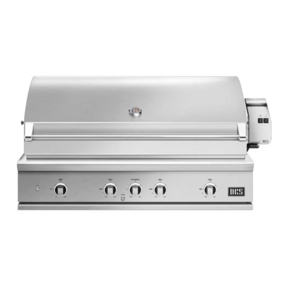
GRILL MODELS BE1-48R BE1-36R... -
Page 9: Product Dimensions
PRODUCT DIMENSIONS BE1-48R Model Illustrated BE1-48R BE1-36R PRODUCT DIMENSIONS Inches (mm) Inches (mm) 27 1/4" (692) 27 1/4" (692) A Overall height of grill 47 15/16" (1217) 35 15/16" (912) B Overall width of grill C Overall depth of grill 26 7/8"... -
Page 10: Installation
INSTALLATION Locating Grill/Built-in Clearances IMPORTANT! Before installation, remove shipping brackets from the grill. Loosen the four screws. Slide the shipping bracket off and re-tighten the screws. Location When determining a suitable location, take into account concerns such as exposure to wind, proximity to traffic paths and keeping any gas or electrical supply lines as short as possible and away from heat sources. - Page 11 INSTALLATION Locating Built-in Clearances PREFERRED AIR FLOW IMPORTANT! Gas fittings, regulator, and installer supplied shut-off valves must be easily accessible. GRILL EXHAUST EXHAUST EXHAUST WIND DIRECTION FLAME LIFT PREFERRED AIR FLOW FIG. 01a FIG. 01b Wind hitting the grill while in use, (especially wind blowing into or across the hood gap) can cause poor performance and in some cases can cause the control panel to get dangerously hot.
- Page 12 INSTALLATION Locating Built-in Clearances Clearances to non-combustible construction* A minimum of 3” (76mm) clearance from the back of the grill to non-combustible construction is required for the purpose of allowing the hood to open fully. It is desirable to allow at least 6” (153mm) rear and side clearance to non-combustible construction above the cooking surface for counter space.
- Page 13 INSTALLATION Locating Built-in Clearances Clearances to combustible construction** Minimum of 18” (457mm) from the sides and rear of grill must be maintained to adjacent vertical combustible construction, above the counter top level. Intense heat, and large volumes of smoke will exhaust from the rear of the grill (Fig.
- Page 14 INSTALLATION Locating Built-in Clearances Clearances to protected combustible construction*** A minimum of 12" (305mm) clearance from the sides and rear of grill must be maintained to adjacent vertical protected combustible construction. Intense heat, and large volumes of smoke will exhaust from the rear of the grill.
-
Page 15: Built-In Construction Details
INSTALLATION Built-in Construction Details Standard layout for non-combustible cavity IMPORTANT! If installing the grill into a non-combustible enclosure, all combustible construction must still be outside the 18" (457mm) clearance zone. If your island is made of stucco over the top of wooden studs, the wood can not be inside the 18 inch clearance zone to combustible, even though the stucco is what is touching the grill area. - Page 16 INSTALLATION Built-in Construction Details Standard layout for cavity including insulated jacket Note: 4x4” (102mm x 102mm) opening for gas supply line Note: the cut-out of each corner should be a 90°angle in order for the access doors/ drawers to fit properly. Note: the enclosure should have ventilation holes to prevent gas build-up in the event of a leak.
-
Page 17: Gas Hook-Up
INSTALLATION Gas Hook-up Gas requirements Verify the type of gas supply to be used, either natural or LP, and make sure the marking on the appliance rating plate agrees with that of the supply. The rating plate is located on the underside of the drip tray. - Page 18 INSTALLATION Gas Hook-up LP cart hook-up Grills orificed for use with LP gas come equipped with a high capacity hose/regulator assem bly for connection to a standard 20 lb. LP cylinder (Type 1). The LP tank is not included. The grill system is leak tested, do not remove the Regulator/Hose assembly from the grill during cart installation.
- Page 19 INSTALLATION Gas Hook-up LP built-in hook-up If the grill is to be installed in a built-in application, then the grill must be installed in accordance with the built–in installation guidelines and the LP regulator/hose assembly must be removed from the product.
-
Page 20: Leak Testing
INSTALLATION Leak Testing IMPORTANT! Gas leak testing must be carried out by a qualified technician. General Regularly check the whole system for leaks, or immediately check if the smell of gas is detected. Before Testing Do not smoke while leak testing. Extinguish all open flames. Never leak test with an open flame. Make a soap solution of one part liquid detergent and one part water. -
Page 21: Electrical Connection
INSTALLATION Electrical Connection IMPORTANT! Use only a Ground Fault Interrupter (GFI) protected circuit with this grill. General Connection to AC Installation requires an outdoor 120VAC 15A GFI (Ground Fault Interrupter) electrical outlet adjacent to the grill. The GFI outlet features an internal breaker that reduces shock hazard. -
Page 22: Burner Adjustment
INSTALLATION Burner Adjustment IMPORTANT! Before lighting, inspect the gas supply piping or hose prior to turning the gas “on”. If there is evidence of cuts, wear, or abrasion, it must be replaced prior to use. Grill burner air adjustment Each grill burner is tested and adjusted at the factory prior to shipment;... -
Page 23: Radiant Assembly
INSTALLATION Radiant Assembly IMPORTANT! Before assembling the radiant, check that the radiant trays have not moved during transit. They should sit securely on their locating pins in the base of the grill. 1 Locate the radiant in the unit. 2 Unpack ceramic rods and remove 3 Unlock radiant end cap by radiant from the unit. -
Page 24: Installer Checklist
INSTALLATION Installer Checklist Specified clearances Air shutters adjusted Check match lighting maintained to combustibles Low flame setting Internal lighting is satisfactory functioning correctly Verified proper enclosure ventilation Drip pan in place properly Transformer is tidy and and sliding freely mounted securely, in a All internal packaging suitable location and any adhesive residue... -
Page 26: Using The Grill
USING THE GRILL Lighting Instructions Grill lighting instructions IMPORTANT! Open the grill hood before lighting. Turn all knobs to “OFF”. Turn the main gas supply on. If you smell gas, shut-off gas supply and call for customer care. Pushing in on the burner knob will activate the Grill Igniter, and then turning the knob from the “OFF” position will allow the flow of gas to the burner. -
Page 27: Grilling
USING THE GRILL Grilling Grill Each grill section consists of a large stainless steel burner, stainless steel heat baffles, a series of ceramic rods encased in a stainless steel radiant, and a stainless steel heat retaining grate. Each burner is rated at 25,000 Btu/hr or 26,5MJ/h. Below the burners there is a stainless steel heat baffle which reflects usable heat upward into the cooking area and reduces temperatures of the drip pan below. - Page 28 USING THE GRILL Grilling Secondary cooking Two racks and one tray have been provided for secondary cooking. These can be utilized for warming, smoking, roasting or slow-cooking food. Before using the secondary cooking surfaces with the grill hood down, ensure that the height and width of food or cooking pans is not excessive. When closing the hood there is a chance that food or cooking pans may be dislodged if these items are too big.
- Page 29 USING THE GRILL Grilling 1 Ensure that the drip pan and grease tray are in place. 2 Light the grill burners following the lighting instructions. 3 Once you have verified the burners are lit, put the hood down to preheat for five to 10 minutes. 4 Place the food on the grill and cook to the desired doneness.
- Page 30 USING THE GRILL Grilling hints The doneness of meat, whether rare, medium or well done, can depend on the thickness of the cut. The cooking time of meat is dependent on the kind of meat, size, shape and cut along with the temperature of the meat when cooking begins.
- Page 31 USING THE GRILL Grilling Cooking Chart - Main Grill and Charcoal Insert POULTRY: TEMP CONTROL APPROX TIME FOOD TYPE THICKNESS WEIGHT METHOD DIAL (HRS/MINS) Chicken Breast Boneless 6 -7 oz Direct/Indirect Medium Heat 10-12 min Chicken Thigh Boneless 3-5 oz Direct/Indirect Medium Heat 10-12 min...
- Page 32 USING THE GRILL Grilling Cooking Chart - Smoking BEEF: TEMP CONTROL APPROX TIME FOOD TYPE THICKNESS WEIGHT METHOD DIAL (HRS/MINS) Brisket 4-6 lb Indirect Low Heat 6-8 hours LAMB: TEMP CONTROL APPROX TIME FOOD TYPE THICKNESS WEIGHT METHOD DIAL (HRS/MINS) Leg of Lamb Roast 3-7 lb Direct/Indirect...
- Page 33 USING THE GRILL Grilling Meat Temperatures The “Remove” temperature on the left is the target temperature to remove from heat source. The “Ideal” temperature on the right is the ideal internal temperature after resting. These temperatures are all Fahren- heit. Note, these are not USDA Recommendations. The USDA temperatures are conservatively 10 –...
- Page 34 USING THE GRILL Grate positions As well as moving the grates to be positioned to your preference along the grill, the dual-sided grates can also be placed flat or in an angled position. If the grates are hot, please use the multi- tool to move the grates or re-position them.
- Page 35 USING THE GRILL Charcoal insert IMPORTANT! Do not use lighter-fluid in the charcoal insert or on the grill. The solid fuel will ignite from the burners, it does not need to be lit by a match or butane lighter. 1 Place charcoal, woodchips or briquettes into the insert. Be careful not to overload with solid fuel (one layer of briquettes is recommended).
-
Page 36: Using The Rotisserie
USING THE ROTISSERIE IMPORTANT! When connecting your rotisserie motor, first connect the motor to the grill and then plug the grill into the outlet. General The grill rotisserie system is designed to cook items from the back using infrared heat. The location of the burner allows the placement of the secondary cooking tray beneath the food to collect juices and drippings for basting and gravy. - Page 37 USING THE ROTISSERIE IMPORTANT! Do not use the rotisserie burner when the secondary cooking racks or trays are in place. Before using the rotisserie burner, ensure that these racks and trays are removed. Preparation Recommended: dental floss or butcher string, scissors, secondary cooking tray, pliers, meat probe, foil, and hot pads.
- Page 38 USING THE ROTISSERIE To light the rotisserie burner before cooking The location of the rotisserie burner makes it more susceptible to strong wind conditions, more so than the protected grill burners. For this reason you should avoid operating the rotisserie during windy conditions.
- Page 39 USING THE ROTISSERIE Grilling 1 Place prepared rod into motor, lay across 2 Once placement has been verified, ignite and into the rollers on other side. burner and start rotisserie motor. Turn the control knob to the desired setting. 3 To check temperature of the meat, turn off 4 Once finished, turn the motor and rotisserie motor and turn temperature to low while knob to “OFF”.
- Page 40 USING THE ROTISSERIE Rotisserie rod storage The rotisserie rod can be stored in the tray located under the grill head. When storing the rotisserie rods, please use two hands to store it correctly and ensure it is locked into place. Please use two hands to remove the rod from its storage compartment, taking care to ensure it does not drop.
-
Page 41: Accessories
ACCESSORIES The following accessories can be purchased separately from authorized DCS dealers. Grill covers To ensure high performance and longevity of your grill, we recommend purchasing a grill cover. Particularly if your grill is going to be stored outside. Storage unit The unit can be bolted onto either side of the grill. -
Page 42: Care & Maintenance
CARE AND MAINTENANCE IMPORTANT! Before each use, inspect the gas supply piping or hose prior to turning the gas “on”. If there is evidence of cuts, wear, or abrasion, on the piping or hose it must be replaced prior to use. Regulator and hose replacement The pressure regulator and hose assembly supplied with the unit must be used. - Page 43 CARE AND MAINTENANCE 304 Stainless steel The grill is made from non-rusting and non-magnetic stainless steel. After initial usage, areas of the grill may discolor from the intense heat given off by the burners, this is normal. There are many different stainless steel cleaners available. Always use the mildest cleaning procedure first, scrubbing in the direction of the grain.
- Page 44 CARE AND MAINTENANCE Burner alignment IMPORTANT! Center the burner onto the orifice properly before lighting the grill to prevent fire hazard or explosion. ⁄ ” KNOB VALVE CONTROL BURNER PANEL VALVE VENTURI REMOVE DRIP PAN TO VIEW CONNECTION Fig. 36 Fig.
- Page 45 CARE AND MAINTENANCE Care of the multi-tool y Wash the multi-tool with hot soapy water after each use. y To protect the condition of the natural wood handle, do not store while wet or in direct sunlight. IMPORTANT! Take care when handling and cleaning the multi-tool, as it has sharp edges that could cause injury. Cleaning the charcoal insert: 1 Once cooled, remove the charcoal insert from inside the grill and dispose of the ash safely.
-
Page 46: Troubleshooting
TROUBLESHOOTING Before calling for service If the grill does not function properly, use the following checklist before contacting your dealer for service. You may save the cost of a service call. Troubleshooting is for general purposes only. If the problem persists and you feel you require service, contact your dealer or the nearest authorized agency to perform service. -
Page 47: Warranty And Service
WARRANTY AND SERVICE Before you call for service or assistance Check the things you can do yourself. Refer to the installation instructions and your user guide and check that: 1 Your product is correctly installed. 2 You are familiar with its normal operation. 3 Model Number (can be found on the inside, right side panel behind the drip pan handle. - Page 49 TABLE DES MATIÈRES Sécurité et avertissements Modèles de gril Dimensions du produit Installation Repérage de la grille / dégagements intégrés Détails de construction intégrés Branchement au gaz Test de fuite Connexion électrique Réglage du brûleur Assemblage radiant Liste de contrôle d'installateur Utilisation du gril Instructions d'allumage Grillage...
- Page 50 UN MESSAGE À NOS CLIENTS Merci d'avoir choisi ce gril DCS Evolution Series. Ce guide d'installation et d'utilisation contient des informations précieuses sur la façon d'installer, d'utiliser et d'entretenir correctement votre nouvel appareil pour des années de cuisson sûre et agréable. S'il vous plaît remplir et soumettre votre enregistrement de produit en visitant notre site Web à...
-
Page 51: Sécurité Et Avertissements
SÉCURITÉ ET AVERTISSEMENTS Pour réduire les risques d'incendie, d'électrocution, de blessures corporelles ou de dommages lors de l'utilisation de l'appareil, suivez les consignes de sécurité importantes ci-dessous: ATTENTION! Danger de surface chaude Les pièces accessibles peuvent devenir chaudes pendant l'utilisation. Ne touchez pas les unités de surface ou les zones proches des unités du gril. - Page 52 SÉCURITÉ ET AVERTISSEMENTS CONSIGNES DE SÉCURITÉ IMPORTANTES! y Après une période de stockage ou de non-utilisation (par exemple pendant l'hiver), vérifiez les fuites de gaz, la détérioration, le bon montage et les obstructions du brûleur avant d'utiliser le gril à gaz. y Toujours utiliser une main couverte lors de l'ouverture du couvercle du barbecue et ne le faire que lentement pour permettre à...
- Page 53 SÉCURITÉ ET AVERTISSEMENTS CONSIGNES DE SÉCURITÉ IMPORTANTES! y PROPOSITION 65 DE LA CALIFORNIE AVERTISSEMENT: La combustion du combustible de cuisson au gaz génère certains sous-produits qui figurent sur la liste des substances reconnues par l'État de Californie comme pouvant causer le cancer ou des problèmes de reproduction. La loi californienne oblige les entreprises à...
- Page 54 GRILL MODÈLES BE1-48R BE1-36R...
-
Page 55: Dimensions Du Produit
DIMENSIONS DU PRODUIT BE1-48R BE1-36R DIMENSIONS DU PRODUIT Pouces (mm) Pouces (mm) Hauteur totale de la grille (692) (692) 15/16 15/16 Largeur totale de la grille (1217) (912) Profondeur totale de la grille (27) (27) (sauf poignée et cadrans) Largeur du châssis 22 (559) 22 (559) 15/16... -
Page 56: Installation
INSTALLATION Repérage des grilles / dégagements intégrés IMPORTANT! Avant toute installation, retirez les supports d’expédition du gril. Pour ce faire, desserrer les 4 vis sur le dessous du gril qui maintiennent les supports au gril. Retirez les supports en les faisant glisser et resserrer les vis. Emplacement Pour déterminer un emplacement approprié, vous devez tenir compte de plusieurs éléments : exposition au vent, proximité... - Page 57 ÉCHAPPEMENT INSTALLATION Repérage des grilles / dégagements intégrés PRÉFÉRÉ FLUX D'AIR IMPORTANT! Les robinets d'arrêt du gaz, le régulateur et les robinets d'arrêt fournis par l'installateur doivent être facilement accessibles. ÉCHAPPEMENT GRILL ÉCHAPPEMENT ÉCHAPPEMENT DIRECTION DU VENT FLAME LIFT PRÉFÉRÉ FLUX D'AIR FIG.
- Page 58 INSTALLATION Localisation des dégagements intégrés Dégagements à la construction incombustible* Un dégagement d'au moins 3 po (76mm) entre l'arrière du gril et une construction incombustible est requis pour permettre l'ouverture complète du couvercle. Il est souhaitable de laisser au moins 6 po (153mm) de dégagement arrière et latéral à...
- Page 59 INSTALLATION Localisation des dégagements intégrés Dégagements à la construction combustible** Un minimum de 18 po (457 mm) des côtés et de l'arrière du grillage doit être maintenu jusqu'à la construction combustible verticale adjacente, au-dessus du niveau du comptoir. Une chaleur intense et de grands volumes de fumée s'échappent de l'arrière de la grille (figure 01b).
- Page 60 INSTALLATION Localisation des dégagements intégrés Dégagements à la construction combustible protégée*** Un dégagement d'au moins 12 po (305 mm) des côtés et de l'arrière du grillage doit être maintenu à la construction combustible adjacente protégée verticalement, une chaleur intense et de grands volumes de fumée s'échappant de l'arrière du gril.
-
Page 61: Détails De Construction Intégrés
INSTALLATION Détails de construction intégrés Disposition standard pour une enceinte non combustible IMPORTANT! Si vous installez le gril dans une enceinte non combustible, toute construction combustible doit toujours être à l'extérieur de la zone de dégagement de 18 pouces. Si votre île est faite de stuc sur le dessus des montants en bois, le bois ne peut pas être à... - Page 62 INSTALLATION Détails de construction intégrés Disposition standard pour la cavité comprenant la veste isolée Remarque: ouverture de 4 x 4 po (102mm x 102mm) pour la conduite d'alimentation en gaz Remarque: la découpe de chaque coin doit être un angle de 90°...
-
Page 63: Branchement Au Gaz
INSTALLATION Branchement du gaz Exigences concernant le gaz Vérifiez le type de gaz à utiliser (gaz naturel ou propane) et assurez-vous que les indications figurant sur la plaque signalétique de l’appareil sont conformes à celles de l’alimentation. L’étiquette de la plaque signalétique est située sur le côté inférieur de l’égouttoir. Ne connectez jamais un tuyau à... - Page 64 INSTALLATION Branchement de gaz Si vous avez l'intention d'installer cette grille sur un chariot, vous devez utiliser un kit de stabilisation de chariot DCS (référence 591604), disponible sur www.dcsappliances.com Raccordement de chariot LP Les grils conçus pour être utilisés avec du gaz de pétrole liquéfié sont munis d'un ensemble tuyau / régulateur de grande capacité...
- Page 65 INSTALLATION Branchement de gaz Branchement intégré LP Si le gril doit être installé dans une application intégrée, le gril doit être installé conformément aux directives d'installation intégrées et l'ensemble régulateur / tuyau flexible doit être retiré du produit. Connexion: Tuyau LP avec un déconnexion rapide et un régulateur de type 1 inclus. Pression de fonctionnement: 11.0 po C.E.
-
Page 66: Test De Fuite
INSTALLATION Test de fuite IMPORTANT! Les tests de fuite de gaz doivent être effectués par un technicien qualifié. Général Bien que toutes les connexions de gaz sur le gril soient testées en usine avant l'expédition, un contrôle complet du gaz doit être effectué sur le site d'installation en raison d'une mauvaise manipulation lors de l'expédition ou d'une pression excessive appliquée à... -
Page 67: Connexion Électrique
INSTALLATION Connexion électrique IMPORTANT! Utilisez uniquement un circuit protégé contre les défauts de mise à la terre (GFI) avec ce gril. Général La connexion à l'installation CA nécessite une prise électrique extérieure 120 V ca 15 A GFI (disjoncteur de fuite à la terre) adjacente au gril. La prise GFI dispose d'un disjoncteur interne qui réduit les risques d'électrocution. -
Page 68: Réglage Du Brûleur
INSTALLATION Réglage du brûleur IMPORTANT! Avant d'allumer, inspectez la tuyauterie d'alimentation en gaz ou le tuyau avant d'allumer le gaz. S'il y a des signes de coupures, d'usure ou d'abrasion, il faut le remplacer avant de l'utiliser. Réglage de l'air du brûleur du gril Chaque brûleur de gril est testé... -
Page 69: Assemblage Radiant
INSTALLATION Assemblée radiante IMPORTANT! Avant d'assembler le radiant, vérifiez que les plateaux radiants n'ont pas bougé pendant le transport. Ils devraient s'asseoir solidement sur leurs goupilles de positionnement dans la base du gril. 1 Localisez le radiant dans l'unité. 2 Déballez les tiges en céramique 3 Déverrouillez le couvercle du et retirez le radiant de l’appareil. - Page 70 INSTALLATION Liste de vérification Dégagements spécifiés Chaque brûleur s'allume Tous les radiants sont maintenus aux de manière satisfaisante, assemblés et mis en place. combustibles. individuellement ou avec le brûleur adjacent allumé. Utilisateur informé du gaz Ventilation correcte de Emplacement de la vanne l'enceinte.
-
Page 72: Instructions D'allumage
UTILISER LE GRIL Instructions d'éclairage Instructions d'allumage du gril IMPORTANT! Ouvrez le couvercle du gril avant de l'allumer. Tournez tous les boutons sur «OFF». Activez l'alimentation en gaz principale. Si vous sentez une odeur de gaz, coupez l'alimentation en gaz et appelez le service à... -
Page 73: Grillage
UTILISER LE GRIL Grillage Gril Chaque section du gril consiste en un gros brûleur en acier inoxydable, une série d’écrans thermiques en acier inoxydable, une série de tiges en céramique encastrées dans une radiant en acier inoxydable, et une grille adiathermique en acier inoxydable. - Page 74 UTILISER LE GRIL Grillage Cuisson secondaire Deux grilles et un plateau ont été prévus pour la cuisson secondaire. Ceux-ci peuvent être utilisés pour réchauffer, fumer, rôtir ou faire cuire lentement des aliments. Avant d'utiliser les surfaces de cuisson secondaires avec le couvercle du barbecue, veillez à ce que la hauteur et la largeur des aliments ou des poêles ne soient pas excessives.
- Page 75 UTILISER LE GRIL Grillage 1 Vérifiez que le ramasse-gouttes et le récipient à graisse sont en place. 2 Allumez les brûleurs du gril en suivant les instructions d'allumage. 3 Une fois que vous avez vérifié que les brûleurs sont allumés, mettez le couvercle vers le bas pour préchauffer pendant cinq à...
- Page 76 UTILISER LE GRIL Grillage La cuisson de la viande, qu'elle soit rare, moyenne ou bien faite, peut dépendre de l'épaisseur de la coupe. Le temps de cuisson de la viande dépend du type de viande, de la taille, de la forme et de la coupe ainsi que de la température de la viande au début de la cuisson.
- Page 77 UTILISER LE GRIL Grillage Tableau de cuisson - Gril principal et insertion de charbon de bois LA VOLAILLE: TEMP CONTRÔLE APPROX TIME TYPE D'ALIMENTATION ÉPAISSEUR POIDS MÉTHODE CADRAN (HRS/MINS) Poitrine de poulet Sans os 6 -7 oz Direct/Indirect Moyen Chaleur 10-12 min Cuisse de poulet Sans os...
- Page 78 UTILISER LE GRIL Grillage Tableau de cuisson - Fumeur DU BOEUF: TEMP CONTRÔLE APPROX TIME TYPE D'ALIMENTATION ÉPAISSEUR POIDS MÉTHODE CADRAN (HRS/MINS) Pointe de poitrine 4-6 lb Indirect Faible Chaleur 6-8 heures AGNEAU: TEMP CONTRÔLE APPROX TIME TYPE D'ALIMENTATION ÉPAISSEUR POIDS MÉTHODE CADRAN...
- Page 79 UTILISER LE GRIL Grillage Températures de la viande La température "Remove" sur la gauche est la température cible à retirer de la source de chaleur. La température "idéale" à droite est la température interne idéale après repos. Ces températures sont toutes Fahrenheit.
- Page 80 UTILISER LE GRIL Positions de grille En plus de déplacer les grilles à positionner selon vos préférences le long de la grille, les grilles à double face peuvent également être placées à plat ou en position inclinée. Si les grilles sont chaudes, utilisez l'outil multifonctions pour déplacer les grilles ou les repositionner.
- Page 81 UTILISER LE GRIL Insert de charbon de bois IMPORTANT! N'utilisez pas de fluide plus léger dans l'insert de charbon ou sur le gril. Le combustible solide s'enflammera à partir des brûleurs, il n'a pas besoin d'être allumé par une allumette ou un briquet au butane.
- Page 82 UTILISATION DE LA ROTISSERIE IMPORTANT! Lorsque vous connectez votre moteur de tournebroche, connectez d'abord le moteur au gril, puis branchez le gril dans la prise. Général Le système de rôtissoire de gril est conçu pour cuire des articles de l'arrière utilisant la chaleur infrarouge. L'emplacement du brûleur permet de placer le bac de cuisson secondaire sous la nourriture pour recueillir les jus et les égouttures pour arrosage et sauce.
- Page 83 UTILISATION DE LA ROTISSERIE IMPORTANT! N'utilisez pas le brûleur de la rôtissoire lorsque les grilles de cuisson secondaires ou les plateaux sont en place. Avant d'utiliser le brûleur de la rôtissoire, assurez-vous que ces grilles et plateaux sont retirés. Préparation Recommandé: soie dentaire ou corde de boucher, ciseaux, lèchefrite (fond seulement), pince, ther- momètre instantané, papier aluminium et poignées isolantes.
- Page 84 UTILISATION DE LA ROTISSERIE Pour allumer le brûleur de la rôtissoire avant la cuisson L'emplacement du brûleur de la rôtissoire le rend plus sensible aux conditions de vent fort, plus que les brûleurs protégés du gril. Pour cette raison, évitez d'utiliser la rôtissoire lorsque le vent souffle. En tant que caractéristique de sécurité...
- Page 85 UTILISATION DE LA ROTISSERIE Grillage 1 Placer la tige préparée dans le moteur, poser 2 Une fois la position vérifiée, allumer le brûleur et en travers et dans les rouleaux de l'autre cô.té démarrer le moteur du tournebroche. Tournez le bouton de commande sur le réglage désiré.
- Page 86 UTILISATION DE LA ROTISSERIE Rangement de tige de rôtisserie La tige de tournebroche peut être stockée dans le plateau situé sous la tête du gril. Lorsque vous stockez les tringles à rôtissoire, utilisez les deux mains pour les ranger correctement et assurez- vous qu'elles sont bien en place.
-
Page 87: Accessoires
ACCESSOIRES Les accessoires suivants peuvent être achetés séparément auprès des revendeurs agréés Fisher & Paykel. Gril couvre Pour assurer la haute performance et la longévité de votre gril, nous vous recommandons d'acheter une couverture de gril. Surtout si votre gril va être stocké à l'extérieur. Unité... - Page 88 SOIN ET MAINTENANCE IMPORTANT! Avant chaque utilisation, inspectez la tuyauterie ou le tuyau d'alimentation en gaz avant d'allumer le gaz. S'il y a des signes de coupures, d'usure ou d'abrasion sur la tuyauterie ou le tuyau, il faut le remplacer avant de l'utiliser. Remplacement du régulateur et du tuyau Le régulateur de pression et le flexible fournis avec l'unité...
- Page 89 SOIN ET MAINTENANCE 304 Acier inoxydable Le gril est fait d’acier inoxydable non magnétique. Après l’utilisation initiale, certaines parties du gril peuvent se décolorer à cause de la chaleur intense dégagée par les brûleurs. Ceci est normal. On trouve toute sorte de nettoyants pour acier inoxydable sur le marché. Employez toujours la méthode de nettoyage la plus douce au début, en frottant dans le sens du grain.
- Page 90 SOIN ET MAINTENANCE Alignement du brûleur IMPORTANT! Centrez correctement le brûleur sur l'orifice avant d'allumer le gril pour éviter tout risque d'incendie ou d'explosion. ⁄ ” BOUTON SOUPAPE CONTRÔLE BRÛLEUR PANNEAU SOUPAPE VENTURI RETIRER LE PANNEAU DE GOUTTELETTE POUR VISUALISER LA CONNEXION Fig.
- Page 91 SOIN ET MAINTENANCE Le soin de l'outil multiple y Laver le multi-outil avec de l'eau chaude savonneuse après chaque utilisation. y Pour protéger l'état de la poignée en bois naturel, ne pas stocker à l'état humide ou à la lumière directe du soleil.
-
Page 92: Dépannage
DÉPANNAGE Avant d'appeler le service Si le gril ne fonctionne pas correctement, utilisez la liste de vérification suivante avant de contacter votre revendeur pour réparation. Vous pouvez enregistrer le coût d'un appel de service. Le dépannage est uniquement à des fins générales. Si le problème persiste et que vous pensez avoir besoin d'un entretien, contactez votre revendeur ou l'agence agréée la plus proche pour effectuer le service. -
Page 93: Garantie Et Réparation
GARANTIE ET RÉPARATION Avant d’appeler pour demander une réparation ou de l’assistance ... Vérifiez les points que vous pouvez contrôler vous-même. Consultez les instructions d’installation et le guide de l’utilisateur pour vous assurer que : 1 Votre produit est installé correctement. 2 Vous êtes familier avec son fonctionnement normal. - Page 96 WWW.DCSAPPLIANCES.COM © Fisher & Paykel Appliances 2019. All rights reserved. The product specifications in this booklet apply to the specific products and models described at the date of issue. Under our policy of continuous product improvement, these specifications may change at any time. You should therefore check with your Dealer to ensure this booklet correctly describes the product currently available.
Need help?
Do you have a question about the DCS BE and is the answer not in the manual?
Questions and answers