Table of Contents
Advertisement
Quick Links
Advertisement
Table of Contents

Subscribe to Our Youtube Channel
Related Manuals for Fisher & Paykel DCS BGB36-BQARN


Summary of Contents for Fisher & Paykel DCS BGB36-BQARN
- Page 1 This Owner's Manual is provided and hosted by Appliance Factory Parts. DCS BGB36-BQARN Owner's Manual Shop genuine replacement parts for DCS BGB36-BQARN Find Your DCS Grill Parts - Select From 274 Models -------- Manual continues below --------...
- Page 2 THE PROFESSIONAL 36/48” BGB GRILL Use and Care Guide MODELS: BGB36-BQAR BGB48-BQAR BGB48-BQR...
- Page 3 A MESSAGE TO OUR CUSTOMERS Thank you for selecting this DCS Professional “BGB” Series Grills. Because of these appliances unique features we have developed this Use and Care Guide. It contains valuable information on how to properly operate and maintain your new appliance for years of safe and enjoyable cooking. To help serve you better, please fill out and submit your Ownership Registration by visiting our website at www.dcsappliances.com and selecting “Customer Service”...
-
Page 4: Table Of Contents
TABLE OF CONTENTS SAFETY PRACTICES & PRECAUTIONS .......................3-5 GRILL MODELS ................................6 GAS REQUIREMENTS ..............................7-8 LOCATING GRILL / BUILT-IN CLEARANCES ..................9-10 BUILT-IN CONSTRUCTION DETAILS ......................11 LEAK TESTING ................................12 INSTALLER FINAL CHECKLIST ...........................13 BURNER ADJUSTMENTS ............................14 USING THE GRILL ..............................15-17 LIGHTING INSTRUCTIONS ..........................17-18 USING THE SMOKER SYSTEM ...........................19... -
Page 5: Safety Practices & Precautions
SAFETY PRACTICES & PRECAUTIONS IMPORTANT SAFETY NOTICE: Certain Liquid Propane dealers may fill liquid propane cylinders for use in the grill beyond cylinder filling capacity. This “Overfilling” may create a dangerous condition. “Overfilled” tanks can build up excess pressure. As a safety device, the tanks pressure relief valve will vent propane gas vapor to relieve this excess pressure. - Page 6 SAFETY PRACTICES & PRECAUTIONS Do not use aluminum foil to line drip pans or grill racks. This can severely upset combustion air flow or trap excessive heat in the control area. The result of this can be melted knobs or ignition buttons.
- Page 7 SAFETY PRACTICES & PRECAUTIONS When using the open top burners always use flat bottomed utensils which are large enough to cover the burner. Adjust the flame so that it heats only the bottom of the pan to avoid ignition of clothing. Position handles inward away from open edges of the unit to avoid burns associated with unintentional spillovers.
-
Page 8: Grill Models
GRILL MODELS IGNITION IGNITION BGB48-BQAR BGB48-BQR BGB36-BQAR... -
Page 9: Gas Requirements
GAS REQUIREMENTS Verify the type of gas supply to be used, either natural or LP, and make sure the marking on the appliance rating plate agrees with that of the supply. The rating Bottom of unit plate is located on the outside of the back wall of the Grill. - Page 10 GAS REQUIREMENTS LP GAS HOOK UP (TYPE 1 OR QCC1 REGULATOR): Grills orificed for use with LP gas come equipped with a high capacity hose/regulator assembly for connection to a standard 20 lb. LP cylinder (Type 1). The LP tank is not included. Connection: 1/2"...
-
Page 11: Locating Grill/Built-In Clearances
LOCATING GRILL/BUILT-IN CLEARANCES INSULATED JACKET: Do not build the Grill under overhead unprotected combustible construction. If the Grill is to be placed into a combustible enclosure, an approved insulated jacket is necessary and is available from your dealer. Use only the DCS insulated jacket which has specifically been designed and tested for this purpose. - Page 12 LOCATING GRILL/BUILT-IN CLEARANCES General The Grill is designed for easy placement into masonry enclosures. For non-combustible applications the grill drops into the opening shown in (Fig. 04) and hangs from its side flanges. A deck is not required to support it from the bottom. When using the insulated jacket in a combustible enclosure application, see the bottom of Fig.
-
Page 13: Built-In Construction Details
BUILT–IN CONSTRUCTION DETAILS grill exhaust 3" (to non-combustible construction / minimum lid clearance) 12" (to combustible construction) 13-3/4" Bottom of support flange 10" 2" 1-1/2" 22" 25-1/2" Standard layout for non-combustible enclosure: NOTE: If using a backguard apron or rear 48"... -
Page 14: Leak Testing
LEAK TESTING GENERAL: Although all gas connections on the grill are leak tested at the factory prior to shipment, a complete gas tightness check must be performed at the installation site due to possible mishandling in shipment, or excessive pressure unknowingly being applied to the unit. Periodically check the whole system for leaks, or immediately check if the smell of gas is detected. -
Page 15: Installer Final Checklist
INSTALLER CHECKLIST/BURNER ADJUSTMENTS INSTALLER FINAL CHECKLIST: ❏ Specified clearances main- ❏ Air shutters adjusted. ❏ User informed of gas supply tained to combustibles. shut-off valve location. ❏ Adjustable low setting satis- ❏ Verified proper enclosure ❏ All radiants are assembled factory. -
Page 16: Burner Adjustments
BURNER ADJUSTMENTS Grill Burner Air Adjustment: Each grill burner is tested and adjusted at the factory prior to shipment; however, variations in the local gas supply or a conversion from one gas to another may make it necessary to adjust the burners. The flames of the burners (except the rotisserie burner) should be visually checked and compared to that of the drawing in Fig.07 and Fig. -
Page 17: Using The Grill
USING THE GRILL GRILL: Each grill section consists of a large stainless steel burner, a stainless steel heat baffles, a series of ceramic rods encased in a stainless steel rack, and a stainless steel heat retaining grate. Each burner is rated at 25,000 Btu/hr. Below burners there is a stainless steel heat baffle which reflects usable heat upward into the cooking area and reduces temperatures of the drip pan below. - Page 18 USING THE GRILL REPLACEMENT OF REGULATORS AND HOSE: The pressure regulator and hose assembly supplied with the unit must be used. The replacement pressure regulators and hose assembly must be the type specified by the manufacturer. Do not use the grill if the odor of gas is present. If the unit is LP, screw the regulator into the tank and leak check the hose and regulator connections with a soap and water solution before operating the grill.
- Page 19 USING THE GRILL/LIGHTING INSTRUCTIONS Grilling Method Note: Indirect cooking method is a popular alternative to direct heat grilling. Indirect cooking uses heat from adjacent burners to cook food and in many cases, reduces the possibility of overcooked or overly browned food. Foods most appropriate for indirect grilling included breads, thicker pieces of chicken or steaks.
-
Page 20: Lighting Instructions
LIGHTING INSTRUCTIONS TO LIGHT DUAL SIDE BURNERS (48BQR MODELS ONLY): CAUTION: The side burner cover may be hot if the grill burners are in operation. Side Burners Lighting Instructions: First remove the burner cover and any cooking utensils from the burner grate. Push and hold the ignition button, turn the control knob to the “HI”... -
Page 21: Using The Smoker System
USING THE SMOKER SYSTEM The smoker system on each grill consists of a stainless steel slide out tray which is positioned above a 3,500 Btu/hr burner. The burner is controlled by a precision brass valve which is capable of being turned down to very low heat levels. The system may be used alone for low temperature roasting and smoking or in conjunction with any combination of other burners. -
Page 22: Using The Rotisserie
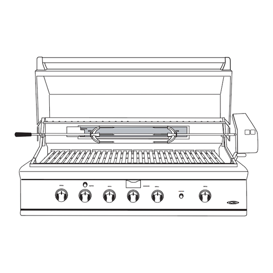
USING THE ROTISSERIE The grill rotisserie system is designed to cook items from the back using infrared heat. The location of the burner allows the placement of the rotis basting pan (included) beneath the food to collect juices and drippings for basting and gravy. To flavor the contents of the basting pan, you can add herbs, onion, garlic, or spices. - Page 23 USING THE ROTISSERIE WARNING: Never have the grill burners (bottom burners) on during Rotisserie cooking. It will burn your meat and make it very dry. Use only one section at a time, grill or rotisserie. PREPARATION Recommended: Dental floss or butcher string, scissors, broiler pan (bottom only), pliers, instant read thermometer, foil, and hot pads.
- Page 24 USING THE ROTISSERIE COOKING ON ROTISSERIE 1. Place prepared rod into motor, lay across to other side in groove. (Fig.27) 2. Verify placement as shown in Fig. 28. 3. Ignite Burner, start Rotisserie Motor, and keep on High for cooking all meats on the Rotisserie. 4.
- Page 25 USING THE ROTISSERIE TO LIGHT THE ROTISSERIE BURNER: The location of the rotis burner makes it more susceptible to strong wind conditions, more so than the protected grill burners. For this reason you should avoid operating the rotis during windy conditions. As an added safety feature we’ve equipped the burner with an automatic safety valve which will not allow gas to flow to the rotis burner unless the following conditions are present with the knob on: 1.
-
Page 26: Care & Cleaning
CARE AND CLEANING BATTERY REPLACEMENT: 1. Remove drip pan. 2. Open cart door. 3. Pull battery downwards (This may require use of pliers.) 4. Re-install upward and push to snap - Fig. 32. (Polarity is shown in FIG. 33 FIG. 32 Fig. -
Page 27: Burner Removal & Cleaning
BURNER REMOVAL AND CLEANING SIDE BURNERS: For proper lighting and performance keep the burners clean. It is necessary to clean the burners if they do not light even though the igniter clicks, if there has been a severe boil over, or when Brass Ring Main the flame does not burn blue. - Page 28 BURNER REMOVAL AND CLEANING ORIFICE CLEANING: With the burner removed, remove the orifice and shine a flashlight through the opening to ensure there is no blockage. Use a needle to clear any debris. Be extremely careful not to enlarge the hole or break off the needle.
-
Page 29: Troubleshooting
TROUBLESHOOTING Before Calling for Service: If the grill does not function properly, use the following checklist before contacting your dealer for service. You may save the cost of a service call. Troubleshooting is for general purposes only. If the problem persists and you feel you require service, contact your dealer or the nearest authorized agency to perform service. -
Page 30: Grill Burner Assembly Parts List
BGB36/48-BQAR GRILL BODY PARTS LIST ITEM DESCRIPTION PART NO. ITEM DESCRIPTION PART NO. Lid, BGB36-BQAR 33184 Firebox, BGB36-BQAR 33200 Lid, BGB48-BQAR 33395 Firebox, BGB48-BQAR 33385 Bolt 15003-06 Rack Roller 14197-02 Stanchion, Lid Handle,R/H 18372-01 Bottom/Back Panel,BGB36-BQAR 33169 Lid Handle, BGB36-BQAR 55773-10 Bottom/Back Panel,BGB48-BQAR 33387... -
Page 31: Grill Body Parts List
BGB48-BQR GRILL BODY PARTS LIST ITEM DESCRIPTION PART NO. ITEM DESCRIPTION PART NO. Lid, BGB36 33184 Handle, Drip Pan, BGB48-BQR 33406 Bolt 15003-06 Drip Pan Assembly, Side Burner, BGB48-BQR 33405 Stanchion, Lid Handle,R/H 18372-01 Handle, Drip Pan, Side Burner 33408 Lid Handle, BGB48-BQR 55773-05 Drip Pan, Side Burner... - Page 32 BGB48-BQR GRILL BODY PARTS LIST...
-
Page 33: Grill Burner Assembly
GRILL BURNER ASSEMBLY ITEM DESCRIPTION PART NO. DESCRIPTION PART NO. Grate BGB Grills 18369 Washer 15005-15 Radiant Assembly BGB 32291-02 Screw 15003-15 Radiant Cap 32264-01 Air Shutter 12003-1 Radiant 32218-02 Control Valve 13017 Ceramic Rods 9.50 32224 Ignition Button 18353 Tube Burner 18408 Wire With Terminals... -
Page 34: Rotisserie Assembly Parts List
ROTISSERIE ASSEMBLY ITEM DESCRIPTION PART NO. ITEM DESCRIPTION PART NO. Fork Rotisserie 18365 Screw 15001-23 Rotisserie Rod, BGB36-BQAR,BGB48-BQR 19507 Acorn Nut 15019-07 Bulb 16235 Rotisserie Rod, BGB48-BQAR 19516 Rotisserie, Motor Assembly Handle, Rotisserie Rod 18040 Right Side Mounting (Standard Configuration) 33060-01 Screw 15001-26 I/R Protection Plate, BGA36-BQAR,BGA48-BQR 41191-PC... -
Page 35: Smoker Burner Assembly Parts List
SMOKER BURNER ASSEMBLY ITEM DESCRIPTION PART NO. Chip Tray 32957 Screw 15001-23 Smoker Burner 30639-1 Electrode, Smoker 16441-02 Screw 15002-42 15004-19 Smoker Burner Support 32226 Control Valve 13017-01 Bezel 14006-PL Knob BGA 14351... -
Page 36: 48 Grill Cart Parts List
48 GRILL CART PARTS LIST ITEM DESCRIPTION PART NO. ITEM DESCRIPTION PART NO. Drawer Box 33029-02 Side Shelf Tray 41067 Side Shelf End Cap 14205 Pull Handle 18462 Rubber Bump 18403 Side Shelf Assembly 18212 Tank Tray Pullout Assembly 33024 Bolt 15003-06 Door Catch... -
Page 37: Grill Cart Parts List
36 GRILL CART PARTS LIST ITEM DESCRIPTION PART NO. ITEM DESCRIPTION PART NO. Drawer Box 33029-01 Side Shelf Tray 41067 Side Shelf End Cap 14205 Pull handle 18462 Rubber Bump 18403 Side Shelf Assembly 18212 Tank Tray Pullout Assembly 33024 Bolt 15003-06 Door Catch... -
Page 38: Wiring Diagram
WIRING DIAGRAM BGB36-BQAR MODELS I/R Burner Electrode #16440-03 Smoker Burner Electrode Burner Electrodes Burner Electrode IgnitionModule 6 Output #18351 9 Volt Battery #18354 #16438-01 Ignition Switch #18353 Wiring Diagram P/N # 32826... -
Page 39: Wiring Diagram Bgb48-Bqr Models
WIRING DIAGRAM BGB48-BQR MODELS I/R Burner Electrode #16440-03 Smoker Burner Electrode Burner Electrodes Burner Electrode IgnitionModule #18352 8 Output Side Burner 9 Volt Battery #18354 Electrodes #12224 #16438-01 #16438-08 #16438-04 #16438-07 #16438-04 Ignition Switch #18353 Wiring Diagram P/N # 33438... -
Page 40: Wiring Diagram Bgb48-Bqar Models
WIRING DIAGRAM BGB48-BQAR MODELS I/R Burner Electrode #16440-03 Smoker Burner Electrode Burner Electrodes Burner Electrodes IgnitionModule 6 Output #18351 9 Volt Battery #18354 Ignition Switch #18353 Wiring Diagram P/N # 32827... -
Page 41: Service
SERVICE HOW TO OBTAIN SERVICE: For warranty service, please contact your local service provider or DCS Customer Care at (888) 281-5698. Before you call, please have the following information ready: Model Number Serial Number Date of installation A brief description of the problem Your satisfaction is of the utmost importance to us. -
Page 42: Warranty
WARRANTY Length of Warranty: One (1) Year Full parts and Labor Covers the entire product Five (5) Year comprehensive warranty covering the porcelainized cast iron rangetop burners, grill radiant assemblies, and drip pans. Should structural deterioration occur to the degree of non-performance, a replacement will be furnished. - Page 43 5900 Skylab Road, Huntington Beach, CA 92647 Tel: 714.372.7000 • Fax: 714.372.7001 Customer Care: (888) 281-5698 www.dcsappliances.com As product improvement is an ongoing process at DCS, we reserve the right to change specifications or design without notice. Part No. 17671 Rev. B Litho in USA 12/04 Litho in USA 09/2001...
Need help?
Do you have a question about the DCS BGB36-BQARN and is the answer not in the manual?
Questions and answers