Table of Contents

Subscribe to Our Youtube Channel
Related Manuals for KAESER KOMPRESSOREN EPC-2-G Series


Summary of Contents for KAESER KOMPRESSOREN EPC-2-G Series
- Page 1 Assembly and operating manual 2-stage piston compressor EPC-2-G No.: 9_5753_04 E Manufacturer: KAESER KOMPRESSOREN GmbH 96410 Coburg • PO Box 2143 • GERMANY • Tel. +49-(0)9561-6400 • Fax +49-(0)9561-640130 http://www.kaeser.com...
- Page 2 Original instructions /KKW/PEPC 1.04 en SBA-KOLBEN-AGGREGAT 2-STUFIG...
-
Page 3: Table Of Contents
Contents Regarding this document Using this document ......................Further documents ......................Copyright .......................... Symbols and markings ..................... 1.4.1 Warning notices ....................1.4.2 Other notices and symbols ................. Technical Specification Nameplate ........................Options ..........................Weight ..........................Compressor block ......................Ambient Conditions ......................Ventilation ........................ - Page 4 Contents 4.2.3 Silenced air filter ....................4.2.4 Air filter with plastic casing .................. 4.2.5 Castors ....................... 4.2.6 Bolt-on machine mounts for mounting on tank ........... Operating modes and control modes ................4.3.1 Operating modes ....................4.3.2 External control unit ................... Safety devices ........................
- Page 5 Contents 10.2.1 Logging maintenance work ................. 10.2.2 Regular maintenance tasks ................10.2.3 Oil change interval ....................10.2.4 Regular service tasks ..................10.3 Maintaining the air cooler or fan guard ................10.3.1 Cleaning the air cooler or fan guard ..............10.4 Air filter maintenance ....................... 10.5 Air filter (noise absorbing) maintenance ................
- Page 6 Contents Assembly and operating manual 2-stage piston compressor EPC-2-G No.: 9_5753_04 E...
- Page 7 List of Illustrations Fig. 1 Location of safety signs ......................Fig. 2 List of main components ......................Fig. 3 Machine layout ........................... Fig. 4 Oil level monitoring ........................Fig. 5 Adjustable machine mountings ....................Fig. 6 Silenced air filter ......................... Fig.
- Page 8 List of Illustrations Assembly and operating manual 2-stage piston compressor EPC-2-G No.: 9_5753_04 E...
- Page 9 List of Tables Tab. 1 The levels of danger and their meaning ..................Tab. 2 Nameplate ..........................Tab. 3 Options ............................Tab. 4 Weight ............................Tab. 5 Compressor block specification ....................Tab. 6 Ambient Conditions ........................Tab. 7 Ventilation ........................... Tab.
- Page 10 List of Tables Assembly and operating manual 2-stage piston compressor viii EPC-2-G No.: 9_5753_04 E...
-
Page 11: Regarding This Document Using This Document
Regarding this document Using this document 1 Regarding this document Using this document This document, hereafter called the service manual, contains important information about all life pha‐ ses of the machine. The service manual is part of the machine. It describes the machine as it was at the time of first delivery after manufacture. -
Page 12: Other Notices And Symbols
Regarding this document Symbols and markings ➤ Always read and comply with warning instructions. Signal word Meaning Consequences of non-observance DANGER Warns of an imminent threat of danger Death or serious injury may result WARNING Warns of possible danger Death or serious injury are possible CAUTION Warns of a possibly dangerous situa‐... -
Page 13: Technical Specification Nameplate
Technical Specification Nameplate 2 Technical Specification Nameplate The machine's nameplate provides the model designation and important technical information. ➤ Enter here the nameplate data as a reference: Feature Value Reciprocating Compressor Part No. Serial No. Year of manufacture Maximum working pressure Delivery Rated voltage Synchronous speed... -
Page 14: Compressor Block
Technical Specification Compressor block Model Weight [kg] EPC 420-2-G 70/160* EPC 550-2-G 95/155* EPC 750-2-G 125/260* EPC 1000-2-G 130/240* * Machine with sound enclosure Tab. 4 Weight Compressor block Model Theoretical displace‐ Delivery at 12 bar Number of cylinders ment [l/min] [l/min] KC 150-2 KC 236-2... -
Page 15: Pressure
Technical Specification Pressure Model Inlet aperture (Z) [m Exhaust fan (A) [m EPC 1000-2-G 0.75 2250 *Forced ventilation: required airflow for static ventilator thrust at maximum duty cycle [ΔT 10 K] Tab. 7 Ventilation Pressure Activating pressure of the cylinder relief valve EPC 150-2 und EPC 230-2 Maximum working pres‐... -
Page 16: Motor Power And Speed
Technical Specification Motor power and speed Model Sound pressure level [dB(A)] Sound pressure level with enclo‐ sure [dB(A)] EPC 1000-2-G Tab. 11 Sound Pressure Level Motor power and speed ➤ Read off the enclosure protection rating from the motor nameplate and enter in the table: Model Rated power Synchronous... -
Page 17: Compressor Oil Charge
Technical Specification 2.11 Power Supply ➤ Mark the oil that your compressor contains in the table below. Standard oil Special oil EPC 150-2/ EPC 420-2 bis EPC 230-2 EPC 1000-2 Oil type SAE 5 W30 VDL 150 S 150 Application Standard oil for all Standard oil for all Specifically for ma‐... -
Page 18: Three-Phase Power Supply
Technical Specification 2.11 Power Supply 2.11.1 Three-phase power supply The machine requires a symmetrical three-phase power supply. In a symmetrical three-phase supply the phase angles and voltages are all the same. This machine may only be supplied from an earthed TN or TT three-phase supply in which the neutral point is earthed. -
Page 19: Tab. 17 Supply Details 400V/3/50Hz
Technical Specification 2.11 Power Supply Rated voltage: 400V±10%/3/50Hz Direct online starting Star-delta starting EPC type Current input Backup fuse Supply cable Backup fuse Supply cable 150-2-G ● 4 x 1.5 230-2-G ● 4 x 1.5 4 x 1.5 420-2-G ● 4 x 2.5 4 x 1.5 550-2-G... -
Page 20: Tab. 19 Supply Details 690V/3/50Hz
Technical Specification 2.11 Power Supply Direct online starting Star-delta starting EPC type Current input Backup fuse Supply cable Backup fuse Supply cable 1000-2-G 10.4 ● 4 x 2.5 – – ● Pressure switch ○ Controller (star-delta) Tab. 19 Supply details 690V/3/50Hz Mains frequency: 60 Hz Rated voltage: 230V±10%/3/60Hz Direct online starting... -
Page 21: Electrical Connection Details For Oil Level Monitoring
Technical Specification 2.11 Power Supply Rated voltage: 440V±10%/3/60Hz Direct online starting Star-delta starting EPC type Current input Backup fuse Supply cable Backup fuse Supply cable 150-2-G ● 4 x 1.5 – – 230-2-G ● 4 x 1.5 – – 420-2-G ●... -
Page 22: Network Conditions
Technical Specification 2.12 Network Conditions 2.12 Network Conditions The machines listed in table are intended for operation with a public power supply with a network impedance at the transfer point (house connection) of maximum Z [Ohm]. The operator must ensure that the machines are only connected to a supply network that meets these requirements. -
Page 23: Tab. 26 Machine Duty Cycle
Technical Specification 2.13 Machine duty cycle Model Permissible duty cycle Cycling period [min] EPC 230-2-G ≤ 70 3–30 EPC 420-2-G ≤ 70 4–30 EPC 550-2-G ≤ 70 4–30 EPC 750-2-G ≤ 70 4–30 EPC 1000-2-G ≤ 70 4–30 Tab. 26 Machine duty cycle Assembly and operating manual 2-stage piston compressor... -
Page 24: Safety And Responsibility Basic Information
Safety and Responsibility Basic Information 3 Safety and Responsibility Basic Information The machine is manufactured to the latest engineering standards and acknowledged safety regula‐ tions. Nevertheless, dangers can arise through its operation: ■ danger to life and limb of the operator or third parties, ■... -
Page 25: Defining Personnel
Safety and Responsibility User's responsibilities ➤ Observe relevant statutory and accepted regulations during installation, operation and mainte‐ nance of the machine. 3.4.2 Defining personnel Suitable personnel are experts who, by virtue of their training, knowledge and experience as well as their knowledge of relevant regulations can assess the work to be done and recognize the possible dangers involved. -
Page 26: Dangers
Safety and Responsibility Dangers Dangers Basic Information Information concerning the various forms of danger that can arise during machine operation are found here. Basic safety instructions are found in this service manual at the beginning of each chapter in the section entitled 'Safety'. - Page 27 Safety and Responsibility Dangers ➤ Do not open or dismantle any valves. Rotating components Touching the fan while the machine is activated can result in serious injury. ➤ Do not open the enclosure while the machine is activated. ➤ Switch off and lock out the power supply disconnecting device and verify the absence of any voltage.
-
Page 28: Safe Machine Operation
Safety and Responsibility Dangers Extending or modifying the compressor station ➤ If a compressor station is to be extended or changed, check the blow-off capacity of the pressure relief valves on air receivers and pipework before installing the new devices. ➤... -
Page 29: Danger Areas
Safety and Responsibility Safety Devices ➤ Give clear instructions on reporting faults and damage to the machine. ➤ Give instructions on fire reporting and fire-fighting measures. 3.5.4 Danger Areas The table gives information on the areas dangerous to personnel. Only authorised personnel may enter these areas. Activity Danger area Authorised personnel... -
Page 30: Information Signs
Safety and Responsibility Information signs Fig. 1 Location of safety signs Item Sign Meaning Danger of fatal injury from electric shock! ➤ Before starting any work on electrical equipment: Switch off and lock out the power supply disconnecting device and check that no voltage is present. -
Page 31: Emergency Situations
Safety and Responsibility Emergency situations Emergency situations 3.9.1 Correct fire fighting Suitable extinguishing agents ■ foam ■ carbon dioxide ■ sand or earth Usuitable extinguishing media ■ Strong jet of water 1. Keep calm. 2. Give the alarm. 3. If possible: Isolate the machine from all power phases. 4. -
Page 32: Environmental Protection
Safety and Responsibility 3.11 Environmental Protection 3.11 Environmental Protection ➤ Store and dispose of operating materials and replaced parts in accordance with local environ‐ mental protection regulations. ➤ Observe relevant national regulations. This applies particularly to parts contaminated with compressor oil. ➤... -
Page 33: Design And Function
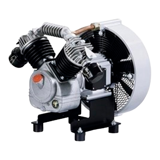
Design and Function Outline of the machine 4 Design and Function Outline of the machine 4.1.1 Main components Fig. 2 List of main components Compressor block Drive motor Sound enclosure 4.1.2 Function Fig. 3 Machine layout Air filter Oil sight glass Compressor block Oil drain plug Electric motor... -
Page 34: Options
Design and Function Options Machine Atmospheric air is drawn through a filter into the compression chamber of the block. The air is drawn in during the downward stroke of the piston. It is compressed during the upward stroke. The com‐ pressed air passes through the inter-stage cooling pipe into the second cylinder where it is further compressed. -
Page 35: Silenced Air Filter
Design and Function Options Fig. 5 Adjustable machine mountings Adjustable machine mountings Threaded joint 4.2.3 Option H9 Silenced air filter The air filter reduces the noise level of the machine. It also cleans the inlet air. Fig. 6 Silenced air filter Air filter element 4.2.4 Option H10... -
Page 36: Castors
Design and Function Options Fig. 7 Air filter with plastic casing Air filter element 4.2.5 Option H14 Castors For easy moving the machine. Fig. 8 Castors Castors Wheel stops 4.2.6 Option H20 Bolt-on machine mounts for mounting on tank For the vibration-free and quiet installation of the machine on, e.g., a compressed air tank. Assembly and operating manual 2-stage piston compressor EPC-2-G... -
Page 37: Operating Modes And Control Modes
Design and Function Operating modes and control modes Fig. 9 Bolt-on machine foot Bolt-on machine foot Threaded joint Operating modes and control modes 4.3.1 Operating modes There are two operating modes: ■ LOAD: The compressor block delivers compressed air. The compressor motor runs under full load. ■... -
Page 38: Safety And Regulating Devices
Design and Function Accessories Enclosures and covers Enclosures and covers over moving parts and electrical connections protect against accidental con‐ tact. 4.4.1 Safety and regulating devices The following safety and regulating devices are to be installed by the user. Pressure relief valve The pressure relief valve protects the air receiver against excessive pressure. -
Page 39: Installation And Operating Conditions
Installation and Operating Conditions Safety 5 Installation and Operating Conditions Safety ➤ Strictly forbid fire, open flame and smoking. ➤ If welding is carried out on or near the machine, take adequate measures to prevent sparks or heat from igniting oil vapours or parts of the machine. ➤... -
Page 40: Ensuring Adequate Ventilation
Installation and Operating Conditions Installation conditions Fig. 10 Recommended machine placement and dimensions [mm] Exhaust fan Air inlet aperture CAUTION Ambient temperature too low. The reduced lubrication properties of oil that is too viscous can result in damage when starting the machine. -
Page 41: Operation In A Compressed Air Network
Installation and Operating Conditions Installation conditions 5.2.3 Operation in a compressed air network When the machine is connected to a compressed air network, the network working pressure may not exceed the permissible working pressure of the machine. ➤ Please contact KAESER for advice. Assembly and operating manual 2-stage piston compressor No.: 9_5753_04 E... -
Page 42: Installation Safety
Installation Safety 6 Installation Safety Here you will find instructions for safe initial start-up of the machine. Warning instructions are located before a potentially dangerous task. Basic safety instructions 1. Follow the instructions in chapter "Safety and Responsibility". 2. Have installation work carried out by authorized installation personnel only. 3. -
Page 43: Compressed Air Connection
Installation Compressed Air Connection Fig. 11 Fitting the antivibration mounts Antivibration mount Hexagonal nut ➤ Remove the wooden frame from the base plate. ➤ Secure the antivibration mounts to the base plate with hexagon nuts. Compressed Air Connection Precondition The compressed air system is vented completely to atmospheric pressure. Fig. -
Page 44: Connecting The Power Supply
Installation Connecting the Power Supply Fig. 13 Suggested Safety and Control Devices Air receiver Pressure gauge Pressure switch Compressed air outlet Check valve Compressed air inlet Flexible hose to the machine Shut-off valve for condensate drainage Pressure relief valve Nozzle (machine-dependent) Test flange ➤... -
Page 45: Options
Installation Options 3. Check the permitted disconnect time for the overload protection cut-out if a fault arises. 4. Use conductor dimensions and fuse ratings in accordance with local regulations (in Germany VDE 0100 parts 430 and 523, for example). 5. The user must provide the machine with a lockable power supply disconnecting device. This could be, for example, a load disconnect switch with fused input. -
Page 46: Fig. 14 Oil Level Monitor Connections
Installation Options Fig. 14 Oil level monitor connections Compressor block Oil level monitor Oil level monitoring and direct online starting Oil level monitoring and star-delta starting Machines with direct online starting and an Machines with star-delta starting require ad‐ under-voltage cut-out on the pressure switch ditional control and connection parts and an require additional control and connection external control unit. -
Page 47: Fig. 15 Changing The Oil Level Monitoring Setting
Installation Options Fig. 15 Changing the oil level monitoring setting Switch cover Adjustment range Screw Higher oil level Red arrow Lower oil level Sensing contact 1. Switch off the machine. DANGER Electric shock! Danger of fatal injury caused by contact with live components. ➤... -
Page 48: Anchoring The Machine
Installation Options 6.7.2 Option H1 Anchoring the Machine Fig. 16 Securing the bolt-on machine mounts Bolt-on machine mountings Threaded joint ➤ Use appropriate fixing bolts to anchor the machine. Further information Details of the anchoring holes are shown in the dimensional drawing in chapter 13.2. 6.7.3 Option H20 Mounting the machine on a compressed air tank... -
Page 49: Retrofitting The Sound Enclosure (Accessory)
Installation Retrofitting the Sound Enclosure (accessory) Retrofitting the Sound Enclosure (accessory) The sound enclosure is supplied already assembled. ➤ The enclosure must be dismantled for fitting to the machine. 6.8.1 Dismantling the sound enclosure Note how the parts fit together. ➤... -
Page 50: Fitting The Sound Enclosure
Installation Retrofitting the Sound Enclosure (accessory) WARNING Compressed air! Compressed air and devices under pressure can injure or cause death if the contained energy is released suddenly or uncontrolled. ➤ Make sure all components and vessels are depressurized and the user's pressure gauge reads 0 bar. -
Page 51: Initial Start-Up Safety
Initial Start-up Safety 7 Initial Start-up Safety Here you will find instructions for safe initial start-up of the machine. Warning instructions are located before a potentially dangerous task. Basic safety instructions 1. Follow the instructions in chapter "Safety and Responsibility". 2. -
Page 52: Checking Installation And Operating Conditions
Initial Start-up Checking installation and operating conditions ➤ Only a competent technician may carry out initial start-up. Special measures for start-up after storage Storage period Action longer than 12 months ➤ Change the Compressor Oil ➤ Have the motor bearings checked by an authorized KAESER Service Tech‐ nician. -
Page 53: Motor Overload Protection
Initial Start-up Motor overload protection Motor overload protection The machine should only be operated with a correctly adjusted motor overload protection switch to protect the motor from overloading. A motor overload protection switch that is set too high provides no protection. Incorrect setting can lead to irreparable damage. -
Page 54: Measuring The Air Receiver Filling Time
Initial Start-up Measuring the air receiver filling time 1. Open the shut-off valve to the air system. 2. Switch on the power supply disconnecting device. The machine switches to LOAD and delivers compressed air. ➤ The machine should be observed during the first few hours in operation in order to detect any faults. -
Page 55: Operation
Operation Switching on and off 8 Operation Switching on and off Always switch the machine on and off with the «ON/OFF» switch. Depending on the starter type, the «ON/OFF» switch may be found on the user's pressure switch or controller. The following starting modes are available: ■... -
Page 56: Direct Online Start With Solenoid Valve
Operation Switching on and off Result The machine starts as soon as network pressure is lower than the cut-out pressure. Switching off 1. Switch off the compressor at the user's pressure switch. 2. Switch off and lock out the power supply isolating device. 8.1.2 Direct online start with solenoid valve Precondition... - Page 57 Operation Switching on and off Result The machine starts as soon as network pressure is lower than the cut-out pressure. Switching off 1. Switch off the machine from the external control unit. 2. Switch off and lock out the power supply isolating device. Assembly and operating manual 2-stage piston compressor No.: 9_5753_04 E...
-
Page 58: Fault Recognition And Rectification
Fault Recognition and Rectification Basic Information 9 Fault Recognition and Rectification Basic Information The alarm indications valid for your machine are dependent on the individual equipment. 1. Do not attempt fault rectification measures other than those given in this manual. 2. -
Page 59: Tab. 35 Faults And Remedies
Fault Recognition and Rectification Alarms Fault Possible cause Action Motor overload protection trips Current too high because of low Check power supply cable con‐ out after a long time. supply voltage. ductor cross-sections. Check and tighten connection termi‐ nals. The machine runs continuously Air filter clogged. -
Page 60: 10.1 Maintenance
Maintenance 10.1 Safety 10 Maintenance 10.1 Safety Follow the instructions below to ensure safe machine maintenance. Warning instructions are found before a potentially dangerous task. Basic safety instructions. 1. Follow the instructions in chapter 'Safety and Responsibility'. 2. Maintenance work may only be carried out by authorized personnel. 3. -
Page 61: Regular Maintenance Tasks
Maintenance 10.2 Maintenance Schedule 10.2.2 Regular maintenance tasks ➤ When operating conditions are unfavourable (e.g. dusty atmosphere) or when the equipment is in constant use, maintenance tasks must be carried out more frequently (shorter intervals). Interval Maintenance task See chapter Daily or every 24 operat‐... -
Page 62: Maintaining The Air Cooler Or Fan Guard
Maintenance 10.3 Maintaining the air cooler or fan guard ➤ When operating conditions are unfavourable (e.g. dusty or humid atmosphere) or when the equipment is in constant use, have the service work carried out more frequently (shorter intervals). Interval Service task Every 2 years at least Change the air filter element Up to 3000 h... -
Page 63: Cleaning The Air Cooler Or Fan Guard
Maintenance 10.4 Air filter maintenance 10.3.1 Cleaning the air cooler or fan guard Do not use sharp objects to clean the air cooler or fan guard. It could cause damage. Avoid creating clouds of dust. ➤ Dry brush the air cooler or fan guard and safety screen using a vacuum cleaner to suck up the dirt. -
Page 64: Air Filter (Noise Absorbing) Maintenance
Maintenance 10.5 Air filter (noise absorbing) maintenance 6. Position the cover over the insert and close the retaining clips. 7. Mount the air filter again. The filter air inlet must face downwards. 8. Switch on the power supply disconnecting device. 10.5 Option H9 Air filter (noise absorbing) maintenance... -
Page 65: Air Filter (With Plastic Casing)
Maintenance 10.6 Air filter (with plastic casing) Cleaning the air filter element by tapping. Cleaning the filter element with compressed air 1. Release the retaining clip and take off the 1. Release the retaining clip and take off the cover. cover. -
Page 66: Drive Motor Maintenance
Maintenance 10.7 Drive Motor Maintenance Cleaning the air filter element by tapping. Cleaning the filter element with compressed air 1. Unscrew and remove the cover. 1. Unscrew and remove the cover. 2. Withdraw the filter element. 2. Withdraw the filter element. 3. -
Page 67: Topping Up The Compressor Oil
Maintenance 10.9 Topping up the compressor oil 10.9 Topping up the compressor oil Material Compressor oil Precondition The power supply isolating device is switched off, the device is locked off, a check has been made that no voltage is present. The machine has cooled down. -
Page 68: Testing The Pressure Relief Valve
Maintenance 10.11 Testing the pressure relief valve Fig. 26 Changing the compressor oil Oil filler port Oil sight glass Oil drain plug Draining the oil 1. Remove the crankcase vent from the oil filler. 2. Position the oil receptacle. 3. Remove the drain plug and allow oil to drain into the receptacle. 4. -
Page 69: Venting The Machine (De-Pressurising)
Maintenance 10.12 Venting the machine (de-pressurising) The valve opens to protect the machine if the maximum permissible working pressure is ex‐ ceeded. ➤ Never operate the machine without a correctly functioning pressure relief valve. ➤ Do not adjust the pressure relief valve. Precondition Machine running under LOAD. -
Page 70: Solenoid Valve Maintenance
Maintenance 10.13 Solenoid Valve Maintenance DANGER Compressed air! ➤ Compressed air and devices under pressure can injure or cause death if the contained energy is released suddenly. ➤ Close shut-off valves or otherwise isolate the machine from the compressed air network to en‐ sure that no compressed air can flow back into the machine. -
Page 71: Changing The Solenoid Valve
Maintenance 10.14 Cylinder head and valves 3. Clean the armature and piston. If the spring and O-ring are damaged or worn they must be replaced. 4. Reassemble the valve. 5. Open the user's shut-off valve between the machine and the air system. 6. -
Page 72: Cleaning The Cylinder Head And Valves
Maintenance 10.14 Cylinder head and valves Precondition Machine at operating temperature. 1. Close the user's shut-off valve between the machine and the air network. 2. Start the machine and measure the receiver charging time. Result The valves should be checked for coking if there is a significant difference between the measured charging time and the charging time when the machine was new. -
Page 73: Document Maintenance And Service Work
Maintenance 10.15 Document maintenance and service work. 10.15 Document maintenance and service work. Machine number: ➤ Enter maintenance and service work carried out in the list. Date Maintenance task carried out Operating hours Signature Tab. 40 Logged maintenance tasks Assembly and operating manual 2-stage piston compressor No.: 9_5753_04 E EPC-2-G... -
Page 74: 11 Spares, Operating Materials, Service
Spares, Operating Materials, Service 11.1 Note the Nameplate 11 Spares, Operating Materials, Service 11.1 Note the Nameplate The nameplate contains all information to identify your machine. This information is essential to us in order to provide you with optimal service. ➤... -
Page 75: Kaeser Air Service
Spares, Operating Materials, Service 11.3 KAESER AIR SERVICE 11.3 KAESER AIR SERVICE KAESER AIR SERVICE offers: ■ authorised service technicians with KAESER factory training, ■ increased operational reliability ensured by preventive maintenance, ■ energy savings achieved by avoidance of pressure losses, ■... -
Page 76: 12.1 Decommissioning, Storage And Transport
Decommissioning, Storage and Transport 12.1 De-commissioning 12 Decommissioning, Storage and Transport 12.1 De-commissioning De-commissioning is necessary, for example, under the following circumstances: ■ the machine is temporarily not needed, ■ the machine is to be moved to another location, ■ the machine is to be scrapped. -
Page 77: Transporting
Decommissioning, Storage and Transport 12.4 Transporting Frozen moisture can damage components, diaphragms, valves and gaskets. Advice can be obtained from KAESER on storage and commissioning. CAUTION Moisture and frost can damage the machine. ➤ Prevent ingress of moisture and formation of condensation. ➤... -
Page 78: Disposal
Decommissioning, Storage and Transport 12.5 Disposal Fig. 32 Transporting with a crane CAUTION The machine can be damaged by incorrect attachment of the lifting gear. ➤ Do not attach the lifting gear to any of the machine components. ➤ The manufacturer can advise on the use of suitable lifting gear. ➤... -
Page 79: 13 Annex
Annex 13.1 Pipeline and instrument flow diagram (P+I diagram) 13 Annex 13.1 Pipeline and instrument flow diagram (P+I diagram) Assembly and operating manual 2-stage piston compressor No.: 9_5753_04 E EPC-2-G... - Page 80 Annex 13.1 Pipeline and instrument flow diagram (P+I diagram) Assembly and operating manual 2-stage piston compressor EPC-2-G No.: 9_5753_04 E...
- Page 81 Annex 13.1 Pipeline and instrument flow diagram (P+I diagram) Assembly and operating manual 2-stage piston compressor No.: 9_5753_04 E EPC-2-G...
-
Page 82: Dimensional Drawing
Annex 13.2 Dimensional Drawing 13.2 Dimensional Drawing Assembly and operating manual 2-stage piston compressor EPC-2-G No.: 9_5753_04 E... - Page 83 Annex 13.2 Dimensional Drawing Assembly and operating manual 2-stage piston compressor No.: 9_5753_04 E EPC-2-G...
- Page 84 Annex 13.2 Dimensional Drawing Assembly and operating manual 2-stage piston compressor EPC-2-G No.: 9_5753_04 E...
- Page 85 Annex 13.2 Dimensional Drawing Assembly and operating manual 2-stage piston compressor No.: 9_5753_04 E EPC-2-G...
-
Page 86: Electrical Diagram
Annex 13.3 Electrical diagram 13.3 Electrical diagram Assembly and operating manual 2-stage piston compressor EPC-2-G No.: 9_5753_04 E... - Page 87 Annex 13.3 Electrical diagram Assembly and operating manual 2-stage piston compressor No.: 9_5753_04 E EPC-2-G...
- Page 88 Annex 13.3 Electrical diagram Assembly and operating manual 2-stage piston compressor EPC-2-G No.: 9_5753_04 E...
- Page 89 Annex 13.3 Electrical diagram Assembly and operating manual 2-stage piston compressor No.: 9_5753_04 E EPC-2-G...
- Page 90 Annex 13.3 Electrical diagram Assembly and operating manual 2-stage piston compressor EPC-2-G No.: 9_5753_04 E...
- Page 91 Annex 13.3 Electrical diagram Assembly and operating manual 2-stage piston compressor No.: 9_5753_04 E EPC-2-G...
- Page 92 Annex 13.3 Electrical diagram Assembly and operating manual 2-stage piston compressor EPC-2-G No.: 9_5753_04 E...
- Page 93 Annex 13.3 Electrical diagram Assembly and operating manual 2-stage piston compressor No.: 9_5753_04 E EPC-2-G...
- Page 94 Annex 13.3 Electrical diagram Assembly and operating manual 2-stage piston compressor EPC-2-G No.: 9_5753_04 E...
- Page 95 Annex 13.3 Electrical diagram Assembly and operating manual 2-stage piston compressor No.: 9_5753_04 E EPC-2-G...
- Page 96 Annex 13.3 Electrical diagram Assembly and operating manual 2-stage piston compressor EPC-2-G No.: 9_5753_04 E...
Need help?
Do you have a question about the EPC-2-G Series and is the answer not in the manual?
Questions and answers