
Related Manuals for Bin Master C-100-R

Summary of Contents for Bin Master C-100-R
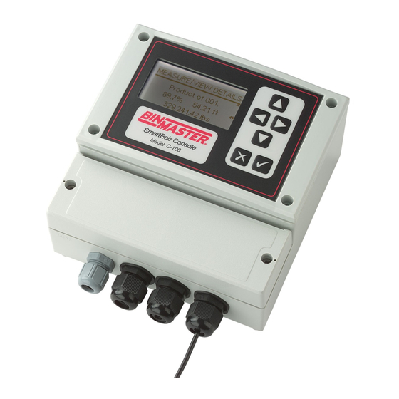
- Page 1 Model C-100-R Modbus Console OPERATORS MANUAL Please read thoroughly before installation and operation. Division of Garner Industries 7201 North 98 Street Lincoln, NE 68507-9741 (402) 434-9102 925-0389 rev A 7/16/2020...
- Page 2 (this page intentionally left blank) 925-0389 rev A...
-
Page 3: Table Of Contents
TABLE OF CONTENTS SAFETY SUMMARY…………………………………….………………………………………………………..…4 1.0 INTRODUCTION……..…………………………………………………………………………………………5 2.0 SPECIFICATIONS……………………………………………………………………………………………...5 3.0 INSTALLATION………………………………………………………………………………………….……...7 3.1 Mounting…………..………………………………………………………………………………….7 3.2 Connections and Wiring……………………………………………………………………....9 3.3 RS-485 Network Requirements……………………………………………………………….……12 3.4 Lightning/Surge Protection…………………………………………………….………………..14 3.5 Wiring Diagram…………………………………………………………………...………………….15 4.0 OPERATION and SETUP….……………………..………………………………………………………….16 4.1 Keypad………………………………………………………………………………..………………16 4.2 Menu System………………………………………………….……………………………………..16 4.3 Messaging System……………………………………………………………………………..……24 5.0 WARRANTY AND SERVICE…………….…………………..……………………………………………..25 5.1 Limited Warranty……………………………………………………………………………………..25 5.2 Technical Support, Customer Service and Repair……………………………………………….25 6.0 DISPOSAL……………………………………………………………………………………………………..26... -
Page 4: Safety Summary
Safety Summary Review the following safety precautions to avoid injury and prevent damage to the equipment. The product should be installed, commissioned, and maintained by qualified and authorized personnel only. Install according to installation instructions and comply with all national and local codes. Use electrical wire that is sized and rated for the maximum voltage and current of the application. -
Page 5: Introduction
The Model C-100-R can interface with up to five BinMaster C-50 Expansion consoles on a dedicated RS- 485 network. The Model C-50 is for interfacing the Modbus sensor system to a PLC or DCS system. Each Model C-50 expansion console supports up to 6 analog I/O cards, each with 4 ports, for a total of 24 analog I/O ports per C-50. - Page 6 Interval Timer for Automatic Measurements Any number of sensors on the network can be configured for an automatic measurement with a time between measurements ranging from 0 seconds (continuous) to 49 minutes and 59 seconds in 1 second increments. Vessel Parameters Vessel Height in feet: 1.00 to 299.99 in 0.01 increments Vessel Height in meters:...
-
Page 7: Installation
If the ambient temperature of the C-100-R is going to exceed 122° F (50° C), consider using a fan of some type to circulate the air. Allowing for good air flow around the C-100-R will prolong the life of the unit. Also, to prolong the life of the unit’s enclosure and front panel, avoid a location that would place it in direct and constant sunlight. - Page 8 3.1.1 Screw Mount There are three screw holes that can be used for mounting the C-100-R control console as shown in the diagram below. You will need one #8 wood screw at least 3/8” long and two #8 wood screws at least 5/8”...
-
Page 9: Connections And Wiring
3.2 Connections and Wiring A minimum configuration will require a three-wire power connection and a three-wire RS-485 connection to the sensor network. Optionally, there may be a two-wire 4-20mA connection, a two-wire external start connection and another three-wire RS-485 connection for the Expansion network. All wiring is fed through water-tight cordgrips and connected inside the lower wiring cabinet to pluggable terminal blocks mounted on the printed circuit board. - Page 10 Devices located at the ends of the sensor network must be properly terminated. For the two devices located at the ends, switch in their NTR or termination resistor. The C-100-R control console can be located anywhere along the network and has a software menu for switching it’s termination in or out of circuit.
- Page 11 These three connections at this terminal block are optional and only needed when connecting BinMaster C-50 expansion units to the system. A good quality twisted-pair shielded cable should be used for the RS-485 network. The cable should connect to each device on the network in a daisy-chain fashion. Branch lines or splits are not recommended.
-
Page 12: Rs-485 Network Requirements
3.2.5 4-20mA Output The 4-20mA Output connection (CN3) is a two wire terminal block located on the far left of the printed circuit board. It is identified with CN3 and labeled with 4-20. The two terminal screws marked + and – should be connected to the proper positive and negative wires of the load. - Page 13 3.5. Observe the polarity of the wiring between all devices on the network, making sure that the wire connected to the + terminal at the C-100-R control console is also connected to the + terminal on all other devices. Likewise, make sure that the wires connected to the – and SH terminals at the C-100-R control console are also connected to the –...
-
Page 14: Lightning/Surge Protection
Both the power source and an RS-485 network are a means for electrical surges to enter the C-100-R control console and do damage. Although some level of protection from electrical surges is built into the C-100-R control console, there are options to further protecting your investment. -
Page 15: Wiring Diagram
3.5 Wiring Diagram 925-0389 rev A... -
Page 16: Operation And Setup
4.0 Operation and Setup The C-100-R control console is controlled and operated using a 6-button icon-based keypad and a simple intuitive text-based menu system. The menu system is user-selectable in either the English or Spanish languages. 4.1 Keypad The keypad consists of 6 membrane style keys appearing as shown to the right. - Page 17 The Scroll Up and Down Indicators, displayed as little up and down arrows towards the right of the screen, will be present when more selections or information is available off screen. The Scroll Up Indicator will be present when the user can scroll up to obtain more selections or information and the Scroll Down Indicator will be present when the user can scroll down to obtain more selections or information.
- Page 18 4.2.1 Main Menu The Main menu has two selections: Measure/View and Setup. Select Measure/View if you want to take an immediate measurement or view the results of the last automated measurement. Select Setup if you need to change user display preferences, setup vessel parameters, sensor network settings or configure the Expansion network.
- Page 19 SB-485 Termination This is a menu for setting whether the sensor bus termination is switched In or Out of the network. If the console is the final device connected at either end of the sensor network choose In, otherwise choose Out. The default setting is In. The termination should be set prior to running Auto Add/Remove or any measurement process.
- Page 20 second screen is for entering the vessel height of the selected vessel(s), the third screen is for setting a headroom offset and the fourth for setting maximum drop distance. Vessel Selection – This is for selecting which vessel or vessels to configure parameters for, choose either Set All or one particular vessel.
- Page 21 Add/Remove prior to making this selection. The default setting is Disabled. After the user selects Enabled, the C-100-R console will automatically assign available I/O’s to enabled sensors and then enter the I/O Assignment menu for the user to review and/or reassign if necessary.
- Page 22 If C-50 setup is disabled, then this menu will be for assigning any single sensor to the C-100-R’s onboard I/O (External Start input and 4-20mA output). The operator simply selects the address of any single sensor in this list, but it defaults to the first address available in the list.
- Page 23 After the interval time has been set, a menu appears for assigning sensors to the automatic measurement process. At least one must be assigned and up to all sensors configured may be assigned. Use the keys to select and accept one or more sensor address’ from the list to the interval timer.
-
Page 24: Messaging System
This is a menu that allows the operator to select either the English or Spanish language for displaying the text-based menu system. The default is English. This menu is also presented to the user when the C-100-R control console is powered up for the very first time. -
Page 25: Warranty And Service
If you are in need of an updated operator's manual, specification drawing or parts replacement list, please visit our online documentation at www.binmaster.com. Prior to shipping your Model C-100-R back for repair, please call our service department for an RMA number. Along with the RMA number, you will also be provided with shipping instructions and address. -
Page 26: Disposal
6.0 Disposal This product consists of materials that may be recycled by certain recycling companies. It uses recyclable materials and is designed to be easily separated. Consult local authorities for proper disposal locations. 925-0389 rev A...
Need help?
Do you have a question about the C-100-R and is the answer not in the manual?
Questions and answers