Table of Contents
Advertisement
Quick Links
User Manual
tSENSE VAV Disp
CO
-, temperature- and
2
relative humidity transmitter
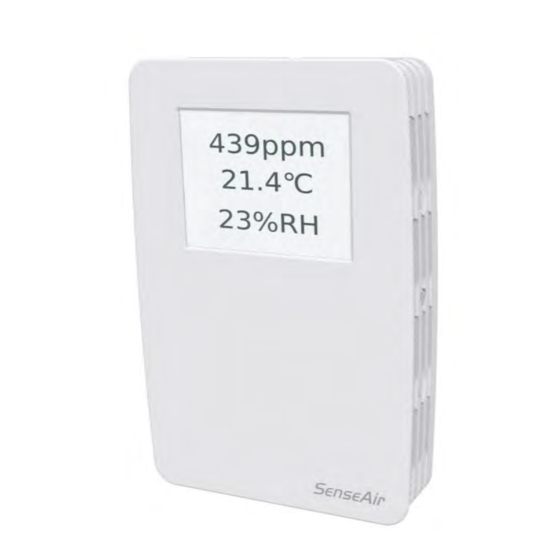
General
for wall mounting measures indoor air carbon dioxide concentration, temperature and
tSENSE VAV
relative humidity in rooms.
is available with colour touch display (LCD).
tSENSE VAV
The unit connects to Direct Digital Control (DDC).
Linear outputs are pre-programmed as CO 2 -, temperature- and relative humidity transmitter.
Measuring ranges can be modified via touch display, from PC (Windows) software UIP (version 5 or
higher) and USB communication cable, alternative via Modbus or BACnet.
Advertisement
Table of Contents

Related Manuals for SenseAir tSENSE VAV


Summary of Contents for SenseAir tSENSE VAV
-
Page 1: General
User Manual tSENSE VAV Disp -, temperature- and relative humidity transmitter General for wall mounting measures indoor air carbon dioxide concentration, temperature and tSENSE VAV relative humidity in rooms. is available with colour touch display (LCD). tSENSE VAV The unit connects to Direct Digital Control (DDC). -
Page 2: Table Of Contents
Table of contents General ..............................1 Opening of housing..........................3 Download of software UIP5 ........................3 Enter PIN code ............................3 PIN1 Delivered product ........................3 PIN2 Delivered product ........................3 Output configurations ........................... 4 Outputs ..............................4 Out1/Out2/Out3 ............................ 4 Voltage range ........................... -
Page 3: Opening Of Housing
Opening of housing Figure 1 Download of software UIP5 senseair.se/products/software/uip-5/ Figure 2: Connection to PC via phone jack Connect Interface cable USB – 3.5mm Art.no.:00-0-0070 Enter PIN code ⓿ Power ON PIN1 Delivered product 0000, Code off PIN2 Delivered product 2001 (if not implemented: 0000) ❶... -
Page 4: Output Configurations
0 - 10 VDC 900 - 1000ppm Table 1. Default output configurations of tSENSE VAV Figure 3: Screw Terminal The sensor is supplied with 0 - 10VDC linear analogue outputs for Out(1), Out(2) and Out(3) (see Table 1). Alternative output ranges can be configured via touch display and/or PC software UIP (version 5 or later). - Page 5 e.g. The largest demand from Proportional-bands is OUT1. Max of Out1_a/ Out1_b/ Out1_c minus (sub) Out1_d => OUT1 Out1Standard Out1_a: CO has a Proportional-band of 600-900ppm Out1_b: Temp has a Proportional-band of 22-23°C Out1_c: RH has a Proportional-band of 75-85%RH Out1_d: Disabled Out1_a Out1_b...
-
Page 6: Voltage Range
Voltage range Max (the same approach with “Min”) ❶ ❷ ❸ ❹ Utgångar ❺ ❻ ❼ ❽ Out2 Out2_a 10.0V, 9.9V..5.0V.. ❾ ❿ UIP5 Select source ❼ ❽ ❾ ❿ Source ❶ ❷ UIP5 Source: CO selected Save Document Page UMA 187 6 (24) -
Page 7: Types
Types Analogue/Analogue Invert ❼ ❽ ❾ ❿ Analogue Analogue invert ❶ ❷ UIP5 Invert Save (Set) Digital/Digital Invert ❿ ❿ Digital Digital Invert Measure range settings Low (the same approach with ”High”) ❼ ❽ ❾ ❿ Low 600ppm 600, 550…400ppm Low 400ppm UIP5 Document... -
Page 8: Relay
Outputs Relay ❶ ❷ ❸ ❹ Outputs ❺ ❻ ❼ ❽ Relay Type Digital ❾ ❿ UIP5 Document Page UMA 187 8 (24) -
Page 9: Communication Settings
❸ NOTE! UIP baudrate ≠ RS-485 baudrate if is connected via phone jack (see fig. 2). tSENSE VAV UIP baudrate = RS-485 baudrate if is connected via screw terminal (see fig. 3). tSENSE VAV To change settings via UIP requires Reset (Power OFF – Power ON) to execute them. - Page 10 Connect meter ❶ ❷ ❸ Information Document Page UMA 187 10 (24)
-
Page 11: Connection Configurations
Lower right corner of screen NOTE! UIP baudrate ≠ RS-485 baudrate if is connected via phone jack (see fig. 2). tSENSE VAV UIP baudrate = RS-485 baudrate if is connected via screw terminal (see fig. 3). tSENSE VAV To change settings via UIP requires Reset (Power OFF – Power ON) to execute them. -
Page 12: Measured Values
Measured values /Temperature/Humidity ❶ ❷ ❸ ❹ ❺ ❻ ❼ ❽ ❾ Document Page UMA 187 12 (24) -
Page 13: Display Settings
Display settings Limits /(Temperature)/(Humidity) Orange/Red limit (Temp./Humidity same method as for CO limit settings) ❶ ❷ ❸ ❹ 100,200…700ppm red limit 1000ppm RH yellow limit 70%RH red limit 1000ppm RH Yellow limit 70%RH Chart 24h/Week ❶ ❷ ❸ ❹ ❺ Document Page UMA 187... -
Page 14: Screen Settings
Screen settings ❶ ❷ Brightness ❸ ❹ ❺ 10, 20,…50% Background ❸ ❹ ❺ ❻ Screensaver, Time setting Interval ❸ ❹ ❺ ❻ 3,4,5…10 s 50 s Document Page UMA 187 14 (24) -
Page 15: Toggle (Time And Co 2 And/Or Temperature And/Or Humidity
Toggle (Time and CO and/or Temperature and/or Humidity Toggle time ❸ ❹ ❺ ❻ ❼ ❽ ❾ ❿ ⓫ ⓬ ⓭ Toggle CO and/or Temperature and/or Humidity ❸ ❹ ❺ ❻ ❼ ❽ ❾ Will NOT show up Document Page UMA 187 15 (24) -
Page 16: Temperature Unit Selection
Temperature unit selection ❶ ❷ ❸ ❹ ❺ ❶ ❷ UIP5 Misc Meter information ❶ ❷ ❸ ❹ ❺ ❻ Document Page UMA 187 16 (24) -
Page 17: Calibration Options Co 2
Calibration options CO ❹ ❺ Zero cal/Background/Target cal ❻ ❼ ❽ ❾ UIP: If reference meter shows e.g. CO -value ❿ ⓫ 500ppm set Target to 500 Background calibration button ❶ ❷ Press 15s, until… Green LED blinks twice Document Page UMA 187 17 (24) -
Page 18: Abc
Enable/Disable ❶ ❷ ❸ ❹ ❺ ❻ ❼ ❽ Activate ABC ❾ Save UIP5 Document Page UMA 187 18 (24) - Page 19 ABC period (ABC target / Altitude / Restore cal) ❺ ❻ ❼ ❽ ❾ ❿ ⓫ ⓬ 180, 181, 240hours Save ⓭ ❶❹ UIP5 Document Page UMA 187 19 (24)
-
Page 20: Offset Temperature/Humidity
Offset Temperature/Humidity ❶ ❷ ❸ ❹ ❺ ❻ ❼ 0.0..-0.1…-0.2°C Automatic system test A full system test is executed automatically at every power-up. Sensor probes are checked constantly during operation against failure by checking valid dynamic measurement ranges. System checks returns error bytes to RAM. Error codes are available by connecting the sensors to a PC with a special USB cable (art.no. -
Page 21: Error Codes And Action Plans
Error codes and action plans Error symbol (a wrench appears when one or several error codes are active) Bit # Error code Error description Suggested action sensor No ability to communicate Try to restart sensor by power Com. error with CO2 sensor module. OFF/ON. -
Page 22: Pin Codes
PIN codes ❶ ❷ ❸ ❹ Create PIN code for access to display settings (PIN1) ❺ ❻ ❼ ❽ PIN1 PIN1 Code Off... PIN(1) Code On Create PIN(1) Code ❾ ❿ Save Create PIN code for access to meter settings (PIN2) ❺... -
Page 23: Maintenance
CO calibrations, unless some special situations have occurred. Software can be downloaded free at www.senseair.com. USB-cable and zero calibration kit can be ordered from SenseAir. Check can be done on site without interfering with ventilation system. Document Page... -
Page 24: Directives
Jiniu High-Tech, Industrial Park Sweden 610036, Chengdu China Phone: +46 (0) 653 - 71 77 70 Phone: +1 (520) 349-7686 Phone: +86 - 028 875 928 85 E-mail: info@senseair.com E-mail: infoamerica@senseair.com E-mail: info@senseair.asia Web: senseair.com Web: senseair.com Web: senseair.asia Document...
Need help?
Do you have a question about the tSENSE VAV and is the answer not in the manual?
Questions and answers