
Related Manuals for YOKOGAWA MG8G


Summary of Contents for YOKOGAWA MG8G
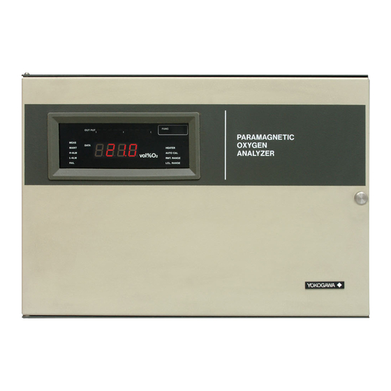
- Page 1 User’s Manual Model MG8G Paramagnetic Oxygen Analyzer IM 11P03A03-01E IM 11P03A03-01E 6th Edition...
-
Page 2: Introduction
Introduction Thank you for purchasing the MG8G Paramagnetic Oxygen Analyzer. Please read the following respective documents before installing and using the MG8G Paramagnetic Oxygen Analyzer. The related documents are as follows. * the “E” in the document number is the language code. -
Page 3: Safety Precautions
• No part of the user’s manuals may be transferred or reproduced without prior written consent from YOKOGAWA. • YOKOGAWA reserves the right to make improvements in the user’s manuals and product at any time, without notice or obligation. • If you have any questions, or you find mistakes or omissions in the user’s manuals, please contact our sales representative or your local distributor. - Page 4 The product is provided on an “as is” basis. YOKOGAWA shall have neither liability nor responsibility to any person or entity with respect to any direct or indirect loss or damage arising from using the product or any defect of the product that YOKOGAWA can not predict in advance. Trademark Acknowledgments We do not use TM or ®...
- Page 5 Blank Page...
-
Page 6: Table Of Contents
Toc-1 Model MG8G Paramagnetic Oxygen Analyzer IM 11P03A03-01E 6th Edition CONTENTS Introduction ....................i Safety Precautions ..................ii OVERVIEW ....................1-1 SPECIFICATIONS ..................2-1 INSTALLATION ..................3-1 Installation Location ..................3-1 Installation Procedure ..................3-1 3.2.1 Panel mounting .................. 3-1 3.2.2 Wall mounting ..................3-2 Piping ......................... - Page 7 Toc-2 6.3.6 Selecting Data ..................6-5 6.3.7 Functions Numbers ................6-6 START-UP ....................7-1 Supplying Power ....................7-1 Warm-up ......................7-2 Analog Output Loop Check ................7-2 Setting the Output Range ................. 7-3 Executing Calibrations ..................7-3 7.5.1 Calibration Gas Requirements ............7-3 7.5.2 Setting Calibration Gas Concentrations ..........
- Page 8 Toc-3 11.3 Precautions When Stopping and Restarting the Operation ...... 11-1 11.4 Fuse Replacement ..................11-1 11.5 Other Instructions ................... 11-2 TROUBLESHOOTING ................12-1 12.1 Errors and Remedies ..................12-1 12.1.1 Checking the Error Code ..............12-1 12.1.2 Error Descriptions ................12-2 12.2 Faulty Readings During Measurement ............
- Page 9 Blank Page...
-
Page 10: Overview
Further, the instrument is provided with one-touch calibration and self-test functions to improve operability, maintainability and reliability. Standard System Configuration The standard system configuration of the MG8G paramagnetic oxygen analyzer is shown in Figure 1.1. The system configuration that includes an automatic calibration option is shown in Figure 1.1. - Page 11 <1. OVERVIEW> System Configuration with Automatic Calibration Atmosphere vent Solenoid valve Model MG8G Analog output Contact output Zero gas Contact input Power supply Span gas Flow control valve Sampling gas Filter Flow meter Auxiliary gas Pressure Pressure V: Valve regulator gauge F2.2E.ai...
- Page 12 <1. OVERVIEW> Name of components Displays and Indicators Operation keys PARAMAGNETIC OXYGEN ANALYZER FUNC OUT PUT MEANS DATA MAINT HEATER H-ALM AUTO CAL vol %O L-ALM MRT.RANGE FAIL AUTO RANGE LCL RANGE SPAN ZERO FUNC ENABLE INHIBIT DECIMAL MEAS/MAINT POINT SHIFT INCR EXEC...
- Page 13 Blank Page...
-
Page 14: Specifications
<2. SPECIFICATIONS> SPECIFICATIONS Measurement Object: Oxygen concentration in gaseous mixture Measurement System: Paramagnetic system Measurement Range: 0-5 to 0-25 vol%O 3 ranges can be programmed arbitrarily within the above specified range. Self-diagnostic content: Sensor unit error, Constant temperature chamber error, Analog error, Memory error, Calibration coefficient error Analog output signal: 4 to 20mA DC (load resistance: Maximum 550Ω) - Page 15 <2. SPECIFICATIONS> Power supply: Power supply Voltage 100 to 115 V AC; Rated voltage range: 100 to 115 V AC Allowable voltage range: 90 to 127 V AC Reted frequency: 50 or 60 Hz Allowable frequency range: 48 to 63 Hz Power supply Voltage 200 to 240 V AC;...
- Page 16 Option Description MG8G - - - - - - - - - - - - - - - - - - - - - - - - - - - - - - - - Paramagnetic oxygen analyzer Measurement range -M...
- Page 17 Blank Page...
-
Page 18: Installation
<3. INSTALLATION> INSTALLATION This chapter describes how to install the analyzer and carry out wiring and line work. Installation Location Take the following requirements into account when choosing the place of installation. (1) Low vibration and mechanical shock levels. (2) Low atmospheric corrosive gas content. If corrosive gas content is too highly, atmospheric purge the case. -
Page 19: Wall Mounting
<3. INSTALLATION> 3.2.2 Wall mounting Locate the mounting brackets to the side of the mainframe as shown by the solid lines in Figure 6.2 and fasten them with bolts (M8×10), spring washers , and plain washers <5> by tightening the bolts lightly. - Page 20 <3. INSTALLATION> Vent Model MG8G Zero gas Span gas Flow control valve Sample gas Filter Flow meter 180 kPa Auxiliary gas Pressure Pressure gauge regulator F6.1E.ai Figure 3.3 Line Diagram Purge air outlet (with blind seal) Purge air inlet (Rc 1/8 female thread) (Note) Always remove the seal protecting the purge air outlet.
- Page 21 Blank Page...
-
Page 22: Wiring
The external connection terminals are located inside the operation panel. To open the panel, loosen the two screws on the panel. Figure 4.1 shows the diagram of the external connection terminals of the MG8G. The terminal numbers are indicated on the instrument. Be sure to make all connections correctly. The terminal screw thread is M4. -
Page 23: Cable Specifications
<4. WIRING> (1) Turn off all the power before wiring. (2) Do not route electrical wiring and wiring for large-capacity converters and motors or power wiring in the same wiring duct. (3) To prevent malfunction due to noise, do not route signal cables and power cables in the same cable hole. -
Page 24: Analog Output Wiring
<4. WIRING> The ground resistance should be 100 Ω or less. The jumper plate between terminals G (26) and FG (27) must remain connected. FG terminal is functional earth terminal. 4.4.2 Analog Output Wiring Connect an analog output cable to the ANALOG OUTPUT terminals, (3) and (4), and the shield wire to the FG terminal, (1) or (2), of the instrument. -
Page 25: Contact Output Wiring
<4. WIRING> WARNNING The power sources for solenoid valves are provided internally. Use solenoid valves that have the same power supply voltage and frequency specifications as the instrument. 4.4.4 Contact Output Wiring All outputs are voltage-free, dry contacts (mechanical relay contacts) and rated 3A at 250 V AC or 30 V DC. -
Page 26: Contact Input Wiring
<4. WIRING> (c) Wiring for Fail Contact Output The contact between terminals 15 and 16 will be activated when an error occurs. The output contact is user configurable to be normally energized (the contact will open when an error occurs) or normally deenergized (the contact will close when an error occurs). For the setting and functions, refer to Chapter 8, Parameter Settings. - Page 27 Blank Page...
-
Page 28: Preparations
<5. PREPARATIONS> PREPARATIONS Adjustment of the Level in the Sensor Unit After the installation is complete, adjust the angle of the sensor unit. (1) Loosen the four screws (, these screws cannot be removed), and remove the constant temperature chamber cover (). (2) Remove the six screws (, 3 each on top and bottom), and remove the heater assembly cover (). -
Page 29: Setting The Auxiliary Gas Pressure
<5. PREPARATIONS> Setting the Auxiliary Gas Pressure Set the pressure of the auxiliary gas to the specified pressure that is indicated on the name plate on the inside of the instrument door. Figure 5.2 shows an example of the name plate that indicates the specified pressure of the auxiliary gas. -
Page 30: Operations
<6. OPERATIONS> OPERATIONS Operation Keys The operation keys on the panel are shown in Figure 6.1 and their functions are summarized in Table 6.1. PARAMAGNETIC OXYGEN ANALYZER FUNC OUTPUT MEAS DATA MAINT HEATER Vol%O H-ALM AUTO CAL L-ALM RMT.RANGE FAIL LCL.RANGE SPAN ZERO... -
Page 31: Displays And Indicators
Lights when range switching function at contact input is disabled. Basic Operations This section describes the basic operations of the MG8G paramagnetic oxygen analyzer. In this section “ (pointer)” in the key operation fields indicates the key to be pressed and light gray characters in DATA fields indicate blinking characters on the display. -
Page 32: Entering The Password
<6. OPERATIONS> 6.3.2 Entering the Password A password is required when setting data or performing calibration in MAINT mode. A password for the instrument is “007” which cannot be changed. The following describes how to enter the password. Key Operation FUNC DATA Procedure... -
Page 33: Entering Values
<6. OPERATIONS> 6.3.5 Entering Values This section explains how to enter values. As an example, the procedure for changing oxygen concentration value in Function No. 02 is shown below. The concentration of span gas is changed from 20.95 to 9.80. Key Operation FUNC DATA... -
Page 34: Selecting Data
<6. OPERATIONS> 6.3.6 Selecting Data This section explains how to select and set one of parameters. As an example, selection of the range is shown below. Key Operation FUNC DATA Procedure Switch to MAINT mode. Enter the password. Press FUNC keys to show “11” on FUNC ZERO SPAN ▲... -
Page 35: Functions Numbers
<6. OPERATIONS> 6.3.7 Functions Numbers The functions assigned to the Function Numbers are listed in Table 6.3. In some functions parameters are not shown unless the password is effective in MAINT mode. Table 6.3 Function Numbers Password Func Function Setting and Range Effective Effective Entering password... -
Page 36: Start-Up
<7. START-UP> START-UP This chapter describes the procedures for supplying power, setting operation parameters, and manual calibration. Supplying Power CAUTION Please attach a terminal cover before switching on the instrument. Before supplying power to the instrument, make sure that: (1) the installation, piping and wiring have been done correctly; (2) the auxiliary gas is being supplied at the specified pressure;... -
Page 37: Warm-Up
<7. START-UP> Warm-up After power up the instrument goes through a warm-up period and then reaches steady state where it is ready for measurement. This section describes how the instrument behaves during the warm-up period. The instrument controls the temperature so that the temperature in the sensor unit is kept at 60 °C. -
Page 38: Setting The Output Range
<7. START-UP> Setting the Output Range The three ranges should be preset to range 1, 2 and 3, respectively and one of the three ranges should be selected. The following describes how to set each range and how to select a range. (1) Switch to MAINT mode and enter the password. - Page 39 <7. START-UP> (5) Press the SPAN key. Turn off the zero gas flow and apply the span gas at the specified flow rate. When solenoid valves for automatic calibration are installed, pressing the SPAN key closes the solenoid valve in zero gas line and opens the solenoid valve in span gas line. (6) The oxygen concentration on the DATA display changes.
-
Page 40: Parameter Settings
<8. PARAMETER SETTINGS> PARAMETER SETTINGS Output Hold Analog output is held at a constant value when the instrument is in the following conditions. • During a warm-up period, analog output is held at 4 mA. • During calibration, analog output is held at the last measured value or is not held (user selectable). -
Page 41: Setting The Output Hold Function When An Error Occurs
<8. PARAMETER SETTINGS> 8.1.2 Setting the Output Hold Function When an Error Occurs The output hold function when an error occurs can be set to “enabled” or “disabled.” When the function is set to “enabled,” the analog output is held at the last measured value or held at a preset value;... -
Page 42: Setting The High/Low Limit Alarms
<8. PARAMETER SETTINGS> Setting the High/Low Limit Alarms The contact is activated to give an alarm when the measured oxygen concentration is outside the limit. High and low alarm limit values can be set, respectively. When the measured value exceeds the high limit alarm value, the H-ALM lamp on the operation panel will turn on and the high limit alarm contact (terminals 10 and 12) will close. -
Page 43: Setting The Range Switching Answerback Contact Output
<8. PARAMETER SETTINGS> Setting the Range Switching Answerback Contact Output The range switching answerback function enables the currently selected range to be output by the contact output (terminals 10, 11 and 12). Since either the range switching answerback function or the high/low limit alarm function can be assigned to this contact, the range switching answerback function cannot be used when the high/low limit alarm function is enabled. -
Page 44: Calibration
<9. CALIBRATION> CALIBRATION Overview The instrument should be calibrated at two points using zero gas (nitrogen gas with an oxygen concentration of 0%) and span gas with a known oxygen concentration. Figure 9.1 shows the relationship between the sensor emf and the oxygen concentration. Sensor emf (mV) p2’... -
Page 45: Checking The Calibration Coefficients
<9. CALIBRATION> k’ Span calibration coefficient Where: k : the ratio of the oxygen concentration to the sensor emf obtained at the initial calibration k’ : the ratio of the oxygen concentration to the sensor emf obtained in calibration When the span calibration coefficient is outside the range of 0.9 to 1.09, a span calibration coefficient error will occur. -
Page 46: Semiautomatic Calibration
<9. CALIBRATION> (1) Switch to MAINT mode and enter the password. (2) Change the Function Number to “01.” The DATA display shows the current oxygen concentration. The display may show the minus sign. The instrument determines the value even if the measured concentration is below zero. The measured concentration when zero gas is applied may be a negative value. -
Page 47: Automatic Calibration
<9. CALIBRATION> CAUTION • For semiautomatic calibration, wiring and piping for automatic calibration are required. • If the calibration start contact remains closed after calibration, the instrument will not accept the next calibration start contact input. The contact should be opened once and then closed again for the next calibration. - Page 48 <9. CALIBRATION> Initial Wait Time Calibration Interval Calibration Interval Calibration Interval Zero Calibration Time Zero Calibration Span Calibration Time Span Calibration Purge Time Output Hold Maintenance Status Contact Action Automatic Calibration Function Starts F12.2E.ai Figure 9.2 Timing Diagram for Automatic Calibration The following describes how to set the automatic calibration.
- Page 49 <9. CALIBRATION> • If the sum of the zero calibration time, span calibration time and purge time is longer than the calibration interval, the next calibration will be canceled. The internal timer works even if the power supply to the instrument is interrupted while the automatic calibration function is enabled.
-
Page 50: Other Functions
10-1 <10. OTHER FUNCTIONS> OTHER FUNCTIONS 10.1 Checking the Temperature of the Constant Temperature Chamber (Function No. 30) The temperature (°C) in the sensor unit can be checked in Function No. 30. It is stable at 60 °C after the instrument entered MEAS mode. 10.2 Checking the Sensor EMF (Function No. - Page 51 10-2 <10. OTHER FUNCTIONS> Table 10.1 Factory Default Settings Func Function Factory Default Entering password Executing calibrations Setting calibration gas concentrations ZERO key: 0.000, SPAN key: 20.95 Checking calibration coefficients Setting output hold function during calibration 0: enabled Initializing calibration coefficient Setting remote range switching contact input 1: disabled Selecting range...
-
Page 52: Inspection And Maintenance
11-1 <11. INSPECTION AND MAINTENANCE> INSPECTION AND MAINTENANCE This chapter describes the inspection and maintenance procedures to ensure optimum performance of the instrument and to keep it in good operating condition. 11.1 Checking the Auxiliary Gas Check that the auxiliary gas is supplied at the specified pressure. When the gas is supplied from a gas cylinder, check the pressure gauge attached to the cylinder. -
Page 53: Other Instructions
11.5 Other Instructions (1) For inspection and maintenance of sampling systems, read corresponding user’s manuals. (2) For the cleaning and overhaul of the sensor unit, consult Yokogawa. (3) Do not use wet paper and cloth for cleaning. IM 11P03A03-01E 6th Edition : Jan. 26, 2022-00... -
Page 54: Troubleshooting
65 °C for at least 10 seconds. to restart. chamber If error occurs again, In warm-up period, heater error E-22 contact Yokogawa Service. temperature fails to rise. Error code blinks on DATA display. Turn off In warm-up period, heater power to heater. E-23 temperature continues to exceed 65 °C for at least 10 seconds. -
Page 55: Error Descriptions
(3) Press the EXEC key to reset the sensor emf error status. Constant Temperature Chamber Errors (E-20, E-21) The temperature of the constant temperature chamber of the MG8G is normally stable at 60 °C during a stabilization period and in steady state. When a constant temperature chamber error occurs, turn the power off and on again to restart, and after the instrument enters a stabilization period, check the temperature of the constant temperature chamber in Function No. -
Page 56: Faulty Readings During Measurement
12-3 <12. TROUBLESHOOTING> Calibration Coefficient Errors (E-50, E-51) A calibration coefficient error occurs if the calibration coefficient obtained in zero or span calibrations is outside the normal range. A zero calibration coefficient error occurs if the zero calibration coefficient is outside of ±1.25% O . -
Page 57: When Calibration Cannot Be Executed
12-4 <12. TROUBLESHOOTING> 12.3 When Calibration Cannot Be Executed • Check that the password has been entered correctly and that the ENABLE lamp is lit. • Check that the instrument is in steady state. If the MAINT lamp blinks in MEAS mode, the instrument is in a stabilization period and calibration cannot be executed. -
Page 58: Measurement Principle
13-1 <13. MEASUREMENT PRINCIPLE> MEASUREMENT PRINCIPLE 13.1 Measurement Principle A diagram of the principle is shown in figure 13.1. When the sample gas contains no oxygen molecules, the right and left flow rates of the auxiliary gas (N ), Q and Q are equal, or Q If oxygen molecules are included in the gas, flow rate Q... - Page 59 13-2 <13. MEASUREMENT PRINCIPLE> For example, if carbon dioxide which has a smaller susceptibility than nitrogen is passed through the cell, the indication deflects to a negative value. If the cell is tilted (angled) to compensate the indication as shown in Figure 13.3, a counterforce acts to supply more auxiliary gas into path A due to the higher density of carbon dioxide, thus changing the flow ratio of the auxiliary gas.
-
Page 60: Customer Maintenance Parts List
Customer MG8G Paramagnetic Oxygen Analyzer Maintenance Parts List Item Part No. Description A1111EF Fuse CMPL 11P03A03-01E All Rights Reserved. Copyright © 2016 Yokogawa Electric Corporation. Subject to change without notice. 1st Edition: Feb. 2016 (YK) -
Page 62: Revision Information
Revision Information Title : Model MG8G Paramagnetic Oxygen Analyzer Manual No. : IM 11P03A03-01E Jan. 2022/6th Edition Removed “11.6 Replacing the limited life component”. Feb. 2016/5th Edition Terminal cover add, chapter change, full review Nov. 2008/4th Edition Revised and style change from *B to *C. - Page 63 Blank Page...
Need help?
Do you have a question about the MG8G and is the answer not in the manual?
Questions and answers