Advertisement
Quick Links
Advertisement

Related Manuals for Nokeval 592D


Summary of Contents for Nokeval 592D
- Page 1 Nokeval 090203 Manual Model 592D...
- Page 2 Nokeval oy Yrittäjäkatu 12 37100 Nokia, Finland Tel. 358-3-342 4800 Fax. 358-3-342 2066...
-
Page 3: Analog Input
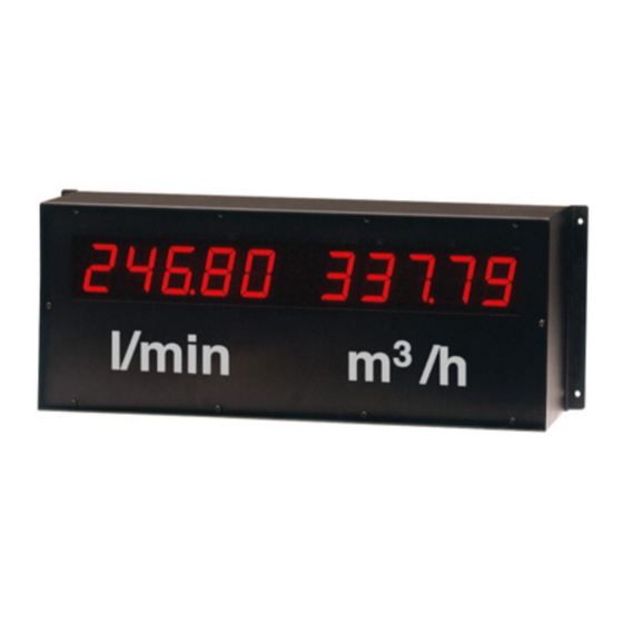
• Microprosessor based • Pt100 sensor, thermocouples, 0/4..20 mA, 0/5..10V, potentiometers Field dsplay 592D has 57 mm digit heigth. The large analog conversion is 15 bit and resolution 1/32000. display is designed for max. 20 meters distance. The field Continuos autocalibration quarantees long term accuracy. - Page 4 Connections Channel B 5/10 V Alarms Thermocoupleand Input: 0/1..5/10VDC: max. 240 V, 2 A mV-input: Contacts: selectable nc or no Pt100 2,3 tai 4- wire Pt100 3-wire. Current 0/4..20 mA: + - c + + + - c + Pt100 Pt100 4-wire.
- Page 5 Keyboard for configuration You can enter configuration stage through three but- You can enter initial setting stage when all indication tons on circuit board. Buttons E and T, on the left, lights are OFF. See chapter "initial settings" on next transfer indication lights in main menu and *-button page.
- Page 6 Configuration You can configurate the meter by three push buttons on circuit board. Display will show symbols, which can be changed, or the settings may be controlled only. *-button will not change settings but it transfers display and program to next stage. Select config stage by pressing E , T and * -buttons at the same time.
-
Page 7: Channel Settings
Channel settings You can configurate both channel individually. Sensor types, alarms, display scaling and output signals. Before channel configuration you shall decide in chapter "Initial Settings" whether one or two channels, secret code etc. will be used. See chapter "Initial settings". Channel A Channel B Channel AB... - Page 8 Select function for channel A or B FU x Linear display log x ln x average (3 measuring values) average (5 measuring values) min. value Reset: press both arrows keys simultaneusly max. value Reset: press both arrows keys simultaneusly EN x Select whether the channel will be displayed by automa- scanning =0 (not displayed), 1= (displayed) ED x...
-
Page 9: Potentiometer Input
Potentiometer input adding output card. Teaching potentiometer position Meter accepts pot. input in both channels, each If the path of the actuator is not from zero to max. having its own scaling. Standard ranges are value but, only a apart of it, you may calibrate meter 0..25...1000 ohm. - Page 10 Definition of mathematical functions for third channel (optional) The display may show the third (extended channel) i.e. the result of the calculations between the two channels. The both signal lights A and B lit at the same time. The third channel operates excatly like the physical channels and may have alarms or output signal.
- Page 11 Functions of channel AB Functions of channel A and B (optional) Table 1 Table 2 Function Function (channel A) (channel B) log x (channel A) ln x (channel B) log x (channel A) 6x e log x (channel B) avg(3 measurements) ln x (channel A) avg(5 measurements),...
- Page 12 Nokeval oy Yrittäjäkatu 12 37100 Nokia, Finland Tel. 358-3-342 4800 Fax. 358-3-342 2066...
Need help?
Do you have a question about the 592D and is the answer not in the manual?
Questions and answers