
Related Manuals for Nokeval 2012


Summary of Contents for Nokeval 2012
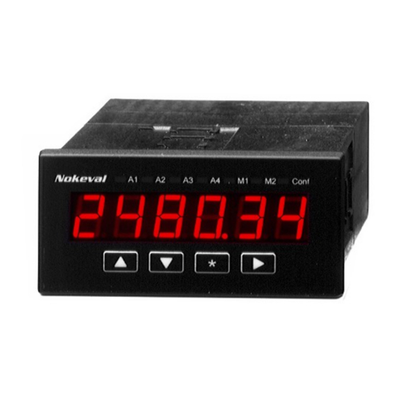
- Page 1 User manual 1.12.2014 Firmware V1.5 2012 2800-2012 910E/920E-2012 1000F-2012 1100F-2012 1800F-2012 For process inputs...
-
Page 2: Table Of Contents
INTRODUCTION 2012 is an input card for measuring mA or V can be used to trigger the hold and tare signal or a potentiometer. The card can be functions. plugged into the 2000 panel meter series, 2012 supports several 2000 series auxiliary... -
Page 3: Connections
Slot A Slot B Slot C Supply -24V+ voltage Slot C Slot B 230VAC Slot A 910E/920E-2012 large panel meter Slot A Conf Slot B Slot C Supply voltage 1000F/1100F/1800F-2012 large field meter See installation chapter on page 11. Cards 2012... -
Page 4: Installing 2000
This chapter gives instructions how to install 1/8 DIN panel meter 2012. The field meter 2800-2012, large panel meter 910/920E-2012 and the large field displays xxxF-2012 have chapters of their own. Opening the enclosure The enclosure has to be opened only, if the jumper positions are changed or a card is added or removed. - Page 5 Supply voltage The power supply is connected in a three-pole connector, that has terminals numbered 7, 8, and 9. The supply is brought to terminals 7 and 9. The polarity does not matter. The 24VDC model has green connector block, while the 230VAC model has a grey one.
-
Page 6: Installing 2800
INSTALLING 2800 Mounting First open the lid with the four plastic screws. The four mounting holes in the corners are exposed. Connections Cable glands There is three PG11 cable glands in the lower wall of the enclosure. Power supply Supply voltage Slot C Slot B... - Page 7 Cards The card connections depend on the card types installed – refer to the chapters of the card types. The terminal 1 is closest to the bottom. Configuration There are several ways to configure the meter: • By using the front panel display and buttons. Using the buttons is described in chapter User interface.
-
Page 8: Installing 910E/920E
INSTALLING 910E/920E Mounting The large panel displays are installed in a rectangular opening in the panel using the two steel holders provided. Clip the holders in the groove and tighten the screw. 1234 Opening 910E5 920E4 920E5 The opening dimensions are given for a tolerance of +2/-1 mm. Connections First detach the lid of the connector room on the backside of the unit. - Page 9 The power supply is brought to the lowest connector terminals 1 and 2. The polarity does not matter. The enclosure may be earthed using the terminal 4. The card slot connections depend on the installed cards – refer to the chapters of the card types.
-
Page 10: Installing 1000F/1100F/1800F
INSTALLING 1000F/1100F/1800F Mounting External dimensions and mounting hole locations for 1000F, 1100F, and 1800F respectively: 500, 670 1045 120,130, 455, 625, 1025 482, 650, 1030 Opening the enclosure To access the electrical connections and the small user interface used for configuring the unit, the steel case has to be opened. - Page 11 24VDC model Main enclosure Protective earth Supply 24 VDC. Free polarity. Electronics unit Supply Slot C Slot B Slot A Flat cable to the large digits Small display and buttons Tw o cable glands Bring the supply voltage to the connector indicated in the picture. A pre-fuse is not necessary, but if one is used, it should be at least 2 AT.
- Page 12 Supply voltage 100…240 VAC or VDC Slot C pow er 230/12V Slot B Slot A Tw o flat cables Bring the Live, Neutral, and Protective Earth wires to the connectors mounted on the DIN rail. The other power supply cabling is factory installed. Cards The card slot connections depend on the installed cards –...
-
Page 13: User Interface
USER INTERFACE LEDs Conf Display Buttons The panel meter front panel and the small display on large displays can be used to view the readings and to change configuration settings. The user interface has four states: • Normal state – indicating readings. •... - Page 14 When the level is displayed, it may be edited Configuration state, editing floating point by pressing either ^ or v. One digit of the numbers. The editing is ended with the * display starts blinking and the level can be button.
- Page 15 and press *. You will be in the slot selection menu. Select another slot or exit with * button. Monitor state Monitoring means viewing some internal The last item in the monitor menu is Diag, values mainly for testing and allowing viewing self-diagnostics messages.
- Page 16 Math/Op • Min: Lesser of the two From1 or From2. • Max: greater of the two. Mathematical operation. The result is placed • Sqrt: Square root from the channel on channel 7. selected with From1. A negative value will give negative results. The operation can be one of the following: Tip: a square of the value can be calculated •...
-
Page 17: Input Card 2012-In
3. The wiper is voltage signal is connected connected in terminal 4. in terminals 4+ and 3-. If using two 2012-IN cards, please note that An active (=remotely they share the common ground (terminals 3 powered) current signal is +24V are internally together). - Page 18 digital converter. The factory-adjusted tare switch is activated. The tare value is calibration values are used to convert the stored in an EEPROM memory and is result to an accurate mA or V reading. This retained even if the power supply is cut off. unprocessed reading can be seen in the The last element in the chain is Dead zone.
- Page 19 used freely, but the Mea settings must be in • Both: Both of the above switches work. ascending order: Mea1 is smaller than Mea2 When the selected switch is activated, the etc. lowpass filter is switched off. Can be used, when the input signal is changed and the If a Lock command is given to a Mea setting filtered reading is desired to jump to that.
- Page 20 Monitor menu The unscaled reading in The scaled reading, that has also gone milliamps/volts/percents depending on the through the lowpass filter, tare subtraction input range. and dead zone function. If a Lock command is given to this item, the Diag meter stops updating the Mea value and allows it to be changed manually.
-
Page 21: Output Card 2000-Out
OUTPUT CARD 2000-OUT Connections The analog output card provides one mA or V output signal. These can not b used at the same time. The analog output card can be installed in slots B or C or both. An active mA output is provided in terminals 4+ and 5-. - Page 22 Rdg1 = 0 analog output will not go under 4 mA nor Out1 = 4 (mA) over 20 mA. Rdg2 = 100 However, if the channel that the output Out2 = 20 (mA) follows indicates fault, the output will always exceed the range between Out1…Out2 by Out/Limit 20% (the output will be Out1+1.2*(Out2-...
-
Page 23: Serial Card 2000-Rs
SERIAL CARD 2000-RS Jumpers No termination, no fail-safe. Middle of the bus devices. Common Terminated, no fail-safe. The last device on the bus. Terminated and fail-safed. The Common last device on the bus if there is no other device providing the fail- safe The serial communications card 2000-RS If there is no devices giving the small voltage... - Page 24 This device accepts the following SCL 0.00000 79800.”. commands: MN xxxxx TYPE ? Configuration commands used by Mekuwin Returns the type and firmware version: ”2012 software. V1.5” without the quotation marks. CARDID slot type MEA CH 1 ? Card type programming. Only for factory use.
-
Page 25: Relay Card 2000-Relx
RELAY CARD 2000-RELX 2000-REL2 and 2000-REL3 are alarm relay slots B and C or both. If the device is to be cards. They have2 or 3 relays equipped with one relay card, it should be correspondingly. The card can be installed in installed in slot C. - Page 26 This applies to the alarm deactivation too, Blink except when the alarm has been programmed to be manually reset. If enabled, the display will be blinked at 1 Hz rate when this alarm is active. ActDelay Only in firmware 1.3 onwards. Defines the time how long the alarm condition must be continuously true before the alarm will actually activate.
-
Page 27: Specifications
SPECIFICATIONS Input card 2012-IN Galv isolation From outputs and supply voltage. If two input cards, they share a common ground. Resolution Not observable (24 bits) Sample rate 15 Hz Overvolt cat Not allowed to be connected in voltage that is more than 120 VDC or 50 VAC with respect to ground. - Page 28 Field meter 2800-2012 Supply voltage Protection class 2 (reinforced insulation) 230VAC model 85…260 VAC or VDC Cat II Environment 24VDC model 12…32 VDC or 20…28 Temperature -10…60°C IP class IP65 Power Max 12 W Large panel meter 910E/920E-2012...
- Page 29 Temperature -10…50°C Power Max 17 W IP class IP54 Protection class 3 (safety low voltage) Large field meter 575F-2012 Protection class 2 (reinforced insulation) Supply voltage 230VAC model 85…260 VAC or VDC Cat II Environment 24VDC model 20…32 VDC Temperature -35…50°C...
Need help?
Do you have a question about the 2012 and is the answer not in the manual?
Questions and answers