Table of Contents
Advertisement
Quick Links
Advertisement
Table of Contents

Subscribe to Our Youtube Channel
Related Manuals for Nokeval PM10A


Summary of Contents for Nokeval PM10A
- Page 1 PM10A chassis Manual Document ID 6380 V16 20.4.2016...
-
Page 2: Table Of Contents
Table of contents Table of contents ................................2 Introduction ..................................3 Assembling a new PM10A ............................... 3 Mounting in a panel ................................ 4 Using the display ................................5 Display contents and pages ....................................5 Automatically configuring the display contents ..............................6 Manually configuring the display contents ................................ -
Page 3: Introduction
Introduction PM10 is a modular panel-installed meter and controller family for industrial use. PM10A is one type of chassis in this family. It is a 96x48 mm panel meter chassis consisting of an enclosure, a motherboard, and a six-digit display. Various types of input and output cards can be fitted inside. -
Page 4: Mounting In A Panel
Prepare a panel cut-out per IEC 61554: width 45.0…45.6 mm, height 92.0…92.8 mm. Place the gasket around the PM10 body. Slide the PM10A in the opening and fasten with two clamps, either on the sides or on top and bottom. -
Page 5: Using The Display
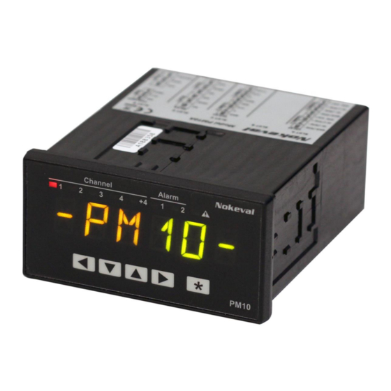
Using the display Alarm indicators Page/channel indicators Fault indicator Indicate the state of the Tell which page is being displayed. Indicates that there is alarms or the relays. Optionally can be used for other something wrong. Optionally can be used for purposes. -
Page 6: Automatically Configuring The Display Contents
Automatically configuring the display contents In most cases, the task of defining the display (page) contents may be left to PM10. It will automatically configure a page for each physical input, beginning from slot A inputs. Since the inputs that are switched off are not included, configure the inputs first according to the input card manuals. -
Page 7: Having Two Readings Simultaneously
Configure the settings for each page under the Page submenus: The informative text or number on the left side of the display. May be blank. The tag should be 0 to 3 letters so that there is still room for the reading. If you want to ensure a gap between the tag and the reading, place a space after the tag. -
Page 8: Making The Display To Scan The Pages
Making the display to scan the pages Scanning means that PM10 automatically displays each page for a moment, then advances to the next. Display Trunk Conf Setpoints Tandem Master Indicators Auto fill Mode Tables Page1 Range Totalizers Page2 Interval Scan Colors Use the following settings under the Display >... -
Page 9: Making The Color To Change At An Event
Making the color to change at an event PM10 can change the display colors to get the user attention e.g. when a critical alarm is triggered. It is called Alarm color. Only one alarm color set is possible in addition to the normal colors. There are two alternative ways to use. -
Page 10: Configuring And Using The Fault Indicator
Configuring and using the fault indicator The PM10 display is continuously querying the other cards if they have any problems. If any of them reports any problems or faults, the Fault indicator will be on. When this happens, use the Fault viewer to see the problem description as guided on page 19. It is possible to adjust the sensitivity of the fault indicator. -
Page 11: Protecting The Configuration With A Password
Protecting the configuration with a password It is possible to prevent unauthorized persons from adjusting the settings in the configuration (and quick configuration) menu of the display card. To do so: 1. Go to the General submenu. 2. Set Conf code. It is a series of six keypresses <v^> (viewed on the front panel) or a series of numbers 1 to 4, e.g. - Page 12 To configure a setpoint, open the Setpoints menu, and then one of the Setp submenus, e.g. Setp1. Configure it: Type See the explanations above. The limits for the Float setpoint. List The user-selectable options for the list type setpoints. Enter the options separated by linefeeds (enter key).
-
Page 13: Having Auxiliary Pages
Having auxiliary pages The trunk pages are arranged vertically – the user may move between them with the v^ keys. Sometimes it may be convenient to have a horizontal motion too. E.g. when viewing a page that contains an input 1 reading, the user might want to see a peak hold value, or adjust an alarm level or a controller set value. -
Page 14: Configuring The Device Using The Front Panel
Configuring the device using the front panel The device can be configured with the Mekuwin software, or using the front panel display and keys. This chapter instructs the latter. Each PM10 card, including the display card, is an independent “device” performing its tasks. Consequently each card has a configuration menu of its own. -
Page 15: Editing A Value
Editing a value The configuration menus contain different types of settings, each being edited differently as detailed below. Common practices: Use v and ^ to edit the value. Use < and > to move the cursor. Long-press * to see a pop-up menu, that provides additional options. ... -
Page 16: Editing A Reference
Editing a reference The references are used to link the different, autonomous blocks of PM10 together. E.g. for an analog output, the source must be configured, as the output may follow various sources (called registers) from any of the cards. Similarly, the display contents are configured to come from somewhere. These are done with a reference to an output register of some card. -
Page 17: Using The Usb Port
Technically the port is connected to the display card (Master). To prepare the port for configuration purposes on a Windows computer: 1. Obtain the PM10 USB driver from Nokeval web site, under Support > Software and drivers. Unzip it to some temporary folder. -
Page 18: Functions, Tables, Elo
Functions, tables, Elo… For processing the input signals and to allow tuning the device for many tasks, the display card provides the following configurable operational blocks: Functions take one or more inputs and do some simple operation on them, like subtracting two inputs. -
Page 19: Maintenance
Maintenance The device doesn’t need regular maintenance. The analog inputs and outputs can be recalibrated, when maximum accuracy is desired. Now and then check that the fault indicator is not on. The enclosure, including the front panel, may be cleaned with a moist cloth. Use mild soap water or isopropyl alcohol. -
Page 20: Specifications
Specifications Environmental Storage temperature -40…+70 °C Operating temperature -30…+70 °C Humidity, front panel 0…100 %RH Humidity, rear 5…90 %RH non-condensing Pollution degree, rear Altitude 0…2000 m when hazardous voltages involved, unlimited otherwise Protection, front panel IP 65 Protection, rear IP 20 Dimensions and weight Digit height 14 mm... -
Page 21: Warnings
Warnings Read this manual carefully before using the device. The device must not be disposed with household waste. Observe local regulations concerning electronic waste recycling. Manufacturer Nokeval Oy Rounionkatu 107 FI-37150 Nokia Finland +358 3 342 4800 (Mo-Fr 8:30-16:00 EET) http://www.nokeval.com/...
Need help?
Do you have a question about the PM10A and is the answer not in the manual?
Questions and answers