Table of Contents
Advertisement
Quick Links
Advertisement
Table of Contents

Related Manuals for Lantronix MatchPort b/g


Summary of Contents for Lantronix MatchPort b/g
- Page 1 MatchPort b/g Integration Guide Part Number 900-485 Revision D December 2011...
-
Page 2: Copyright And Trademark
Copyright and Trademark © 2011 Lantronix. All rights reserved. No part of the contents of this book may be transmitted or reproduced in any form or by any means without the written permission of Lantronix. Printed in the United States of America. -
Page 3: Revision Table
FCC ID cannot be used on the final product (including the transmitter) and obtaining a separate FCC authorization. Note: Changes or modifications to this device not explicitly approved by Lantronix will void the user's authority to operate this device. Revision Table Date Rev. -
Page 4: Table Of Contents
About the Integration Guide ________________________________________________ 6 Additional Documentation__________________________________________________ 6 2: Description and Specifications MatchPort b/g Overview ___________________________________________________ 7 MatchPort b/g Block Diagram _______________________________________________ 8 PCB Interface ___________________________________________________________ 9 Mating Connector ________________________________________________________ 9 Serial Input/Output ______________________________________________________ 10 Sample Layouts for RS-485 Connectivity _____________________________________ 11... -
Page 5: List Of Figures
Figure 2-10. Wireless Connector Dimensions ________________________________________ 18 Figure 2-11. PCB Layout (Top View) ______________________________________________ 18 Figure 2-12. Product Label ______________________________________________________ 19 Figure 3-1. MatchPort b/g Demo Board Layout _______________________________________ 23 Figure 3-2. Demo Board Schematics ______________________________________________ 24 List of Tables Table 2-1. -
Page 6: 1: Introduction About The Integration Guide
The intended audiences are the engineers responsible for integrating the MatchPort b/g into their product. Additional Documentation The following guides are available on the product CD and the Lantronix Web site (www.lantronix.com) MatchPort b/g Briefly explains the basics to get the MatchPort Demonstration Kit Quick b/g up and running. -
Page 7: 2: Description And Specifications
It includes a wireless connection, an operating system, an embedded Web server, and a full TCP/IP protocol stack. In addition, the MatchPort b/g sends email alerts and supports numerous other network communication protocols, including ARP, UDP, TCP, ICMP, Telnet, AutoIP, DHCP, HTTP and SNMP. -
Page 8: Matchport B/G Block Diagram
2: Description and Specifications MatchPort b/g Block Diagram The following drawing is a block diagram of the MatchPort b/g showing the relationships of the components. Figure 2-1. MatchPort b/g Block Diagram MatchPort b/g Integration Guide... -
Page 9: Pcb Interface
No connect Signal Ground No connect Note: For all the configurable pins, see the MatchPort b/g User Guide for selectable functions. Mating Connector MatchPort can be soldered directly to the PCB using the footprint shown in Figure 2-10. If a socket is required, two 2 mm 20-pin sockets spaced 1.42" apart can be used (e.g., Samtec P/N SMM-120-02-S-S-TR). -
Page 10: Serial Input/Output
2: Description and Specifications Figure 2-3. U.FL to U.FL Cable (P/N 500-181-R) Note: The antenna cable is included in the MatchPort b/g sample. For production, it can be purchased from Lantronix or a cable supplier. Serial Input/Output The unit has two serial ports compatible with RS232 serial standards at data rates up to 921 Kbps. -
Page 11: Sample Layouts For Rs-485 Connectivity
Data Out TX-485 TXD2 Data Out RX+485 RXD2 Data In RX-485 RXD2 Data In RTS2 TX Enable RS-485 Select RS-485 2-wire Sample Layouts for RS-485 Connectivity Figure 2-4. Combined RS-232/422 Transceiver Figure 2-5. Separate RS-232/422 Transceivers MatchPort b/g Integration Guide... -
Page 12: Wlan Input/Output
3.3V with a series resistor of 220 ohm. Note: If you have questions or concerns, please contact Lantronix Technical Support at (800) 422-7055 (US only) or (949) 453-7198. If power management is disabled, and when the unit is associated with a network, the receiver will always be on and thus any LED output, that indicates the receiver or transmitter being on will be active continuously. -
Page 13: Power, Ground, And Reset
Reset Pin 37 Pin 2 Pin 1 Pin 39 Driving the Reset In line low resets the MatchPort b/g. Minimum reset pulse width is 2 ms at IIL = -500uA. Absolute Maximum Ratings Table 2-6. Absolute Maximum Ratings Parameter Units Supply Voltage 3.135... -
Page 14: Wireless Specifications
2: Description and Specifications Wireless Specifications Refer to the following table for the MatchPort b/g’s wireless specifications: Table 2-8. Wireless Specifications Category IEEE 802.11b/g Frequency Range 2.400 – 2.484 GHz Output Power 14 +2.0/- 1.5 dBm 1, 2, 5.5, 11 Mbps 12 +/- 1.5 dBm 6, 9, >... -
Page 15: Technical Specifications
2: Description and Specifications Technical Specifications Table 2-9. Technical Specifications Category MatchPort b/g CPU, Memory Lantronix DSTni-EX 186 CPU, 256 KB zero wait state SRAM 2048 KB Flash,16 KB Boot ROM Firmware Upgradeable via TFTP and serial port Reset Circuit Reset In is low active. -
Page 16: Dimensions
2: Description and Specifications Dimensions The MatchPort b/g dimensions are shown in the following diagrams. All tolerances +-.005in unless otherwise noted. Figure 2-7. Side Views MatchPort b/g Integration Guide... -
Page 17: Figure 2-8. Top View
2: Description and Specifications Figure 2-8. Top View Figure 2-9. Bottom View MatchPort b/g Integration Guide... -
Page 18: Recommended Pcb Layout
2: Description and Specifications Figure 2-10. Wireless Connector Dimensions Recommended PCB Layout The hole pattern and mounting dimensions for the MatchPort b/g device server are shown in the following drawing: Figure 2-11. PCB Layout (Top View) MatchPort b/g Integration Guide... -
Page 19: Product Information Label
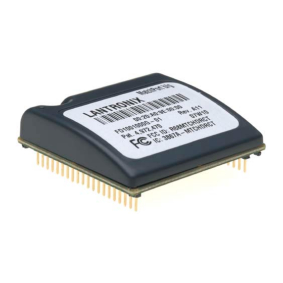
Product Information Label The product information label contains important information about your specific unit, such as its product ID (name), bar code, part number, and MAC address. Figure 2-12. Product Label Part Number MAC Address Revision Manufacturing Code MatchPort b/g Integration Guide... -
Page 20: 3: Demonstration Kit
It supplies 3.3V power. The MatchPort demo board provides access to all signals to and from the MatchPort b/g device server. The demo board has two serial port interfaces (CON1 and CON2). The MatchPort b/g demo board also includes an RJ45 connector for use with wired Ethernet. -
Page 21: Power Supply
Jumper 5-6, CP3 Controls LED10 7/CP4 8/LED9 Jumper 7-8, CP4 Controls LED9 9/CP5 10/LED8 Jumper 9-10, CP5 Controls LED8 11/CP6 12/LED7 Jumper 11-12, CP6 controls LED7 13/CP7 14/LED6 Jumper 13-14, CP7 controls LED6 15/CP8 16/LED5 Jumper 15-16, CP8 controls LED5 MatchPort b/g Integration Guide... -
Page 22: Table 3-4. Demo Board Jp7 Jumper Configuration For Con1
JP7, CON1 DTR LED11 JP7, CON1 DCD LED10 JP7, CON1 RS-485/232 Select LED9 JP7, CON1 RS-485 Duplex Select LED8 JP8, CON2 DTR LED7 JP8, CON2 DCD LED6 JP8, CON2 RS-485/232 Select LED5 JP8, CON2 RS-485, Duplex Select MatchPort b/g Integration Guide... -
Page 23: Demo Board Layout
3:Demonstration Kit Demo Board Layout Figure 3-1. MatchPort b/g Demo Board Layout MatchPort b/g Integration Guide... -
Page 24: Demo Board Schematics
3:Demonstration Kit Demo Board Schematics Figure 3-2. Demo Board Schematics MatchPort b/g Integration Guide... - Page 25 3:Demonstration Kit MatchPort b/g Integration Guide...
- Page 26 3:Demonstration Kit MatchPort b/g Integration Guide...
- Page 27 3:Demonstration Kit MatchPort b/g Integration Guide...
-
Page 28: A: Compliance And Warranty Information
CAN/CSA-C22.2 No. 60950-1-03 EN 60950-1:2001, Low Voltage Directive (73/23/EEC) EMC & Radio: For purposes of certification, the MatchPort b/g was tested as a modular device. CFR Title 47 FCC Part 15, Subpart B and C, Class B FCC Module Approval... -
Page 29: Warranty
A:Compliance and Warranty Information RoHS Notice All Lantronix products in the following families are China RoHS-compliant and free of the following hazardous substances and elements: • • • Lead (Pb) Mercury (Hg) Polybrominated biphenyls (PBB) • • • Cadmium (Cd)
Need help?
Do you have a question about the MatchPort b/g and is the answer not in the manual?
Questions and answers