Table of Contents
Advertisement
Quick Links
Advertisement
Table of Contents

Related Manuals for Lantronix MSS485


Summary of Contents for Lantronix MSS485
- Page 1 MSS485 Installation Guide For the Lantronix MSS485 Micro Serial Server...
-
Page 2: Table Of Contents
1.1 RS-485 Networking Overview .........1-2 1.1.1 RS-485 Protocols........1-2 1.1.2 Two-wire Mode........1-2 1.1.3 Four-wire Mode ........1-3 1.2 Terms ................1-4 1.3 Protocols..............1-5 1.4 Software ..............1-6 1.5 Configuration .............1-6 Installation 2.1 MSS485 Components..........2-1 2.2 Installation ..............2-3 2.2.1 Power-up Diagnostics ......2-6 2.3 Is It Working? .............2-7... - Page 3 Getting Started 3.1 IP Address Configuration.........3-2 3.1.1 Using a BOOTP or RARP Reply ..3-2 3.1.2 Using an ARP Entry and the Ping Command3- 3.1.3 Using the Serial Console ......3-3 3.2 Incoming Logins ............3-4 3.2.1 Controlling Incoming Logins ....3-4 3.2.2 EZWebCon Login and Configuration3-4 3.2.3 Other Incoming TCP/IP Logins ..3-4 3.2.4 Incoming LAT Logins ......3-5 3.3 Serial Port Logins............3-5...
- Page 4 Using the MSS 5.1 Host-Initiated Connections ........5-2 5.1.1 Socket Connections.......5-2 5.1.2 LAT Connections ........5-3 5.1.3 Host Applications .........5-4 5.1.4 Code Examples........5-4 5.2 Interactive Connections ..........5-5 5.2.1 Session Control........5-5 5.2.2 Outgoing Connections ......5-7 5.2.3 Status Displays ........5-9 5.3 Emulating a Direct Serial Connection.....5-11 5.4 Multihost Mode............5-13 Technical Support Troubleshooting...
-
Page 6: Introduction
file index.htm in the root directory of the CD. Then click on the link to the MSS Reference Manual. The PostScript and PDF versions of the MSS485 manuals are located in the manuals directory of the CD. Use the Adobe Acrobat Reader (widely available on the Internet at no charge) to read and print all or parts of the manual from the file mssref.pdf. -
Page 7: Rs-485 Networking Overview
• The maximum RS-485 network cabling length (without repeaters) is 4,000 feet. Lantronix recommends the use of shielded twisted- pair cabling. 1.1.1 RS-485 Protocols A large number and variety of protocols run over RS-485. However, the MSS does not convert or interpret serial data. -
Page 8: Four-Wire Mode
Introduction RS-485 Networking Overview On a two-wire RS-485 network, the MSS must turn its transmitter on when it is ready to send data and then off a certain period of time after the data has been sent so that the line is available to receive again. At most baud rate settings, the timing delay is typically one character length with a maximum of 1.5 character lengths. -
Page 9: Terms
Terms Introduction 1.2 Terms In this manual, the following terms are used to describe parts of a network. Host A computer attached to the network. The term host is generally used to denote interactive computers, or computers that people can log into. Any intelligent device directly connected to the Node Ethernet network such as a host, a printer, or a... -
Page 10: Protocols
Introduction Protocols 1.3 Protocols A network protocol is a method of communicating over the Ethernet. Each protocol specifies a certain arrangement of data in the Ethernet packets, and provides different services for its users. The MSS supports the following protocols: •... -
Page 11: Software
NOTE: For more information about methods used to configure an IP address, see page 3-1. Lantronix has provided EZWebCon software to help users install and configure the MSS. It is also possible to configure the MSS settings by logging into it over a network via Telnet or Rlogin. See Chapter 3, Getting Started, for more information. -
Page 12: Installation
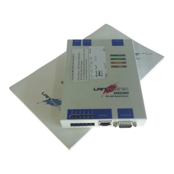
Read this section completely before continuing. 2.1 MSS485 Components The MSS485 front panel has a screw terminal block and an RJ45 port for an RS-485 serial connection, as well as an RS-232 DB9 console port. Figure 2-1: MSS485 Front Panel... - Page 13 LED patterns are part of the normal operation of the MSS and are not necessarily indicative of errors or dangerous operation. The top of the MSS485 also contains an oval-shaped hole in the lower left corner. The hole accommodates a screwdriver, which is needed to attach cabling wires to the screw terminal block.
- Page 14 Installation Installation Figure 2-4: MSS485 Bottom Label Showing DIP Switches Switch Group Functions 2 Wire 485 4 Wire 485 4 Wire 485 Termination 2 Wire 485 Termination No Termination 2 or 4 Wire 485 RX Biasing No RX Biasing Ground Shield Float Shield 2.2 Installation...
- Page 15 Figure 2-6: Connecting Wire to Screw Terminal Block Screwdriver Wire NOTE: Lantronix recommends the use of shielded twisted pair cabling for RS-485 serial connections. To ensure that data wires are connected properly see RS-485 Networking Overview on page 1-2 and Appendix C, Pinouts.
- Page 16 Installation Installation NOTE: The DB9 console port parameters are 9600 baud, 8 data bits character size, no parity, and one stop bit. 5. Set the eight DIP switches on the bottom of the unit to correspond with your network. Choose one option from each of the following functional groupings, and be sure not to mix two-wire and four- wire mode settings.
-
Page 17: Power-Up Diagnostics
NOTE: Ensure that you are using the MSS six volt power supply. The Lantronix EPS1, EPS2, and LRS2 units have a power supply that looks similar to the MSS power supply, but is a different voltage. -
Page 18: Is It Working
Installation Is It Working? When the unit is running normally, the OK LED blinks green once every two seconds. If data is being transmitted on the Ethernet port, the OK LED blinks yellow. The Serial LED blinks red when characters are transmitted through the serial port, green when characters are received, and yellow when characters are both transmitted and received. -
Page 20: Getting Started
MSS. • Remote console logins cannot be disabled. The system manager should always be able to access the unit. • Only one terminal may be connected to the MSS485 DB-9 console port. 3 - 1... -
Page 21: Ip Address Configuration
IP Address Configuration Getting Started 3.1 IP Address Configuration When using IPX or LAT, it is possible to power up the MSS and have it work properly with no additional configuration required. For TCP/IP use, an IP address must be configured for the MSS before any TCP/IP functionality is available. -
Page 22: Using The Serial Console
Getting Started IP Address Configuration NOTE: The ARP/ping method is also available under Windows NT. Refer to your Windows NT documentation or the Lantronix FAQs available from http://www.lantronix.com for information about the ARP tables. When the server receives the ping packet, it will notice that its IP address is not set and will send out broadcasts to see if another node is using the specified address. -
Page 23: Incoming Logins
Incoming Logins Getting Started 3.2 Incoming Logins 3.2.1 Controlling Incoming Logins Incoming Telnet logins are enabled by default, and incoming LAT logins are disabled. This behavior can be changed with the Change Incoming command and one of the following parameters: Telnet Enables Telnet logins Enables LAT logins... -
Page 24: Incoming Lat Logins
Getting Started Serial Port Logins 3.2.3.2 Rlogin Rlogin allows users to connect to a remote device as if they were on the local network. Rlogin is enabled by default. 3.2.4 Incoming LAT Logins To get an MSS login prompt when connecting from a LAT host, use the command below and substitute the last six bytes of the MSS hardware address for xxxxxx. -
Page 25: Starting Outbound Connections
Trying 192.0.1.88 Connected to 192.0.1.88 Escape character is ‘^]’ # access (not echoed) Lantronix MSS Version n.n/n (yymmdd) Type Help at the ‘Local>’ prompt for assistance. Enter Username> jerry 3.5 Starting Outbound Connections When logged into the MSS, users can make basic outgoing connections using the methods on the following page. -
Page 26: Spx
Getting Started Logout 3.5.2 SPX For SPX connections, the MSS and the target device must advertise themselves via SAP announcements. To view all available SPX devices (those advertising themselves) type Show Nodes SPX at the Local prompt. Then type “SPX” followed by the target device’s SAP name. Figure 3-7: SPX Connection Local>... -
Page 28: Configuration
Configuration Command Set 4 - Configuration Certain parameters must be configured before the MSS can function in the network. EZWebCon is the recommended way to communicate with and configure the MSS. This chapter shows an additional method of configuration: the command line interface and MSS command set. NOTE: Instructions for using EZWebCon are included with the soft- ware. -
Page 29: Login Password
Protocol Configuration Configuration If another user is currently the privileged user for the MSS, use the Set Privileged Override command to forcibly become the privileged user. To relinquish privileged status, enter the Set Noprivilege command. The privileged password can be changed with the Change Privpass command. -
Page 30: Ipx/Spx Parameters
Configuration Protocol Configuration • Name Resolution: Hosts on TCP/IP networks generally have a text hostname and a numeric IP address. The MSS can resolve text host names into the numeric equivalents needed for most connections, provided that a DNS (domain name server) has been configured. CHANGE NAMESERVER 192.0.1.167 A default domain name can also be configured for the purpose of name resolution. -
Page 31: Lat Parameters
Serial Port Configuration Configuration All four frame types are enabled by default. Internal routing must be enabled when more than one frame type is enabled, and enabling routing enables all four frame types. CHANGE NETWARE INTERNAL ROUTING DIS CHANGE NETWARE ENCAPSULATION SNAP EN 4.3.3 LAT Parameters •... - Page 32 Configuration Serial Port Configuration • Baud Rate: Specify a baud rate of 300, 600, 1200, 2400, 4800, 9600 (the default), 19200, 38400, 57600, or 115200 baud. CHANGE SPEED 19200 • Character Size: The MSS can use 8 data bits (the default) or 7. CHANGE CHARSIZE 7 •...
- Page 33 Serial Port Configuration Configuration A dedicated service is configured the same way as a preferred service. No dedicated service is configured for the MSS by default. CHANGE DEDICATED LAT:LN=vax8:LD=0005 • Autostart: Normally, the serial port will wait for a carriage return before starting a connection.
-
Page 34: Using The Mss
Using the MSS 5 - Using the MSS This chapter explains how to use the MSS interactively and with host applications. Host-initiated connections include: • Making socket connections to TCP/IP and IPX/SPX hosts. NOTE: There are no services on the MSS. All connections are made via sockets. -
Page 35: Host-Initiated Connections
Host-Initiated Connections Using the MSS 5.1 Host-Initiated Connections 5.1.1 Socket Connections Each node on a network has a node address, and each node address can allow connections on one or more sockets. Sometimes these sockets are referred to as ports. TCP/IP and IPX connections can be made directly to the MSS serial port using sockets. -
Page 36: Lat Connections
Using the MSS Host-Initiated Connections 5.1.2 LAT Connections Most VMS applications require the creation of a LAT application port to access the MSS serial port. Programs can use the LAT application port as they would use a physical port for input and output. For example, an application might be configured to use port LTA3419 which would allow it to access a device connected to the MSS serial port. -
Page 37: Host Applications
Host-Initiated Connections Using the MSS 5.1.3 Host Applications The MSS can be used with applications on Unix, Windows, Windows NT, OS/2, LAT, and Macintosh hosts, and any other hosts that have a TCP/IP or SPX socket interface. When a host application makes a socket connection to the MSS, it uses the socket as a data pipe to send and receive data. -
Page 38: Interactive Connections
Using the MSS Interactive Connections 5.2 Interactive Connections Interactive mode refers to entering commands at the Local prompt. Commands can be used to configure the MSS, connect to remote services, manipulate a connection, or receive feedback. 5.2.1 Session Control When a user makes a connection to a service on the network (via Telnet, Rlogin, SPX, or LAT), a session is created. - Page 39 Interactive Connections Using the MSS No backward or forward switch keys are enabled by default. They must be explicitly defined using the commands in Figure 5-8. To specify a control character, precede it with a carat (^). Figure 5-8: Defining Switches Local>>...
-
Page 40: Outgoing Connections
Using the MSS Interactive Connections 5.2.1.5 Session Limits The number of active session a user can have on the MSS is limited by three factors: available server memory resources, a server-wide limit, and a port-specific limit. The absolute maximum number of sessions for the MSS is eight. To reduce the limit further, enter the Change Session Limit command followed by a number from one to seven. - Page 41 Interactive Connections Using the MSS 5.2.2.2 Rlogin Rlogin allows a user to log into a remote host as if he or she were a local user. For example: Figure 5-10: Connecting with Rlogin Local> RLOGIN shark A user’s MSS username (the name used for login to the MSS) becomes the login name for the remote host.
-
Page 42: Status Displays
Using the MSS Interactive Connections To connect to a LAT service, type the word “LAT” followed by the service name. To view available LAT nodes and services, enter Show Nodes LAT or Show Services at the Local> prompt. The example below shows how to connect to the highest-rated service named modem on the network. - Page 43 Interactive Connections Using the MSS 5.2.3.2 Show IPsecurity This command shows the current TCP/IP security table, if one exists. Addresses or ranges of addresses are listed according to the kind of restrictions placed upon them. 5.2.3.3 Show NetWare All necessary information related to IPX/SPX connections can be viewed including the name of the NetWare loadserver and the number of frames transmitted.
-
Page 44: Emulating A Direct Serial Connection
Using the MSS Emulating a Direct Serial Connection 5.2.3.8 Show Server Counters This command enables the system administrator to view quantitative information about send and receive errors. It also displays error information for the Ethernet and TCP/IP protocols that can be used to diagnose network transmission problems. - Page 45 Emulating a Direct Serial Connection Using the MSS Assuming the MSS serial port parameters have been configured properly, they would be configured as follows: mss_a Local>> CHANGE DEDICATED TCP 192.168.5.10:3001T Local>> CHANGE AUTOSTART ENABLED mss_b Local>> CHANGE ACCESS REMOTE Local>> CHANGE DEDICATED NONE Local>>...
-
Page 46: Multihost Mode
Using the MSS Multihost Mode NOTE: Autostart can be disabled if you want the MSS to wait for a carriage return before sending data. Also, the Autostart char- acter can be changed, if desired, using the Change Autostart command. 5.4 Multihost Mode Multihost mode is used to set up a data pipe between a serial device attached to the MSS and multiple hosts on the network. - Page 47 Multihost Mode Using the MSS In the previous example, the UDP host entry is actually a broadcast IP address. Data would be sent to all hosts on that particular subnet. NOTE: Any changes to the host table don't take effect until the port is logged out or the MSS is initialized.
-
Page 48: Technical Support
Phone: (949) 453-3990 Fax (949) 453-3995 Technical Support Phone: (800) 422-7044 or (949) 453-7198 Fax: (949) 450-7226 On-line: www.lantronix.com/support If you are submitting a problem, please provide the following information: • Your name, company name, address, and phone number •... -
Page 50: Troubleshooting
B - Troubleshooting This Appendix discusses how to diagnose and fix errors quickly yourself without having to contact a dealer or Lantronix. It will help to connect a terminal to the serial port while diagnosing an error to view any summary messages that will be displayed. - Page 51 Problems and Error Messages Troubleshooting Table B-1: Problems and Error Messages, cont. Problem/Message Error Remedy The MSS completes There is a problem with the Check the terminal setup and the its power-up and serial connection or the set-up physical connections, including the boot procedures, but of the serial device.
- Page 52 Troubleshooting BOOTP Troubleshooting B.2 BOOTP Troubleshooting BOOTP failure does not disable the unit from booting. If the BOOTP request fails even though you have configured your host to respond to the request, check the following areas: Table B-2: BOOTP Troubleshooting Area to Check Explanation Is BOOTP in your...
- Page 53 TFTP Troubleshooting Troubleshooting B.3 TFTP Troubleshooting If the TFTP request fails even though you have configured your host to respond to the request, check the areas discussed in the following table. Table B-3: TFTP Troubleshooting Area to Check Explanation Is TFTP enabled on Ensure that the /etc/inetd.conf file has an uncommented line the loadhost? enabling the TFTP daemon.
- Page 54 Troubleshooting Entering Commands at the Boot Prompt A series of commands called Boot Configuration Program (BCP) commands can be entered at the Boot prompt to configure the MSS. These commands are a subset of the entire MSS command set. For example, a typical TCP/IP configuration might use the following commands: Figure B-1: BCP Command Examples Boot>...
- Page 55 Entering Commands at the Boot Prompt Troubleshooting NOTE: The Ethernet address should have been set at the factory. Setting an incorrect address could cause serious network problems. – Ipaddress ip_address specifies this server’s IP address. Uses the standard numeric format. –...
-
Page 56: Pinouts
Pinouts Console DB9 Connector C - Pinouts In the following diagrams, unlabeled pins are not connected. C.1 Console DB9 Connector The figure below shows the pin connections of the MSS DB9 connector. Figure C-1: Pinout of DB9 Console Port RX TX Shield C.2 RS-485 Connectors The RJ45 and Screw Terminal Block RS-485 connectors are wired in parallel. - Page 57 Shield Shield C.3 DIP Switches There are eight DIP switches located on the bottom of the MSS485, labeled left to right. For more information about their configuration, see Installation on page 2-5. Figure C-4: DIP Switch Block and Label on Bottom of MSS...
-
Page 58: Specifications
Specifications Power Specifications D - Specifications This appendix lists the power requirements, temperature requirements, altitude limitations, and relative humidity limitations of the MSS. D.1 Power Specifications The MSS is supplied with a power cube adaptor that has the following specifications. 110 Volts AC domestic Adapter input voltage: 220 Volts international... - Page 59 Altitude Limitations Specifications D.4 Altitude Limitations Operating: 2.4 km (8,000 ft) Storage: 9.1 km (30,000 ft) If you are operating the MSS above 2.4 km (8,000 ft), decrease the operating temperature rating by 1.8˚C for each 1,000 m (1˚F for each 1,000 ft). D - 2...
-
Page 60: Warranty Statement
If the product is not under warranty, Lantronix will contact the customer who then has the option of having the unit repaired on a fee basis or having the unit returned. - Page 61 In no event will Lantronix be responsible to the user in contract, in tort (including negligence), strict liability or otherwise for any special, indirect, incidental or consequential damage or loss of equipment, plant or power system, cost of capital, loss of profits or revenues, cost of replacement power, additional expenses in the use of existing...
- Page 62 Declaration of Conformity (according to ISO/IEC Guide 22 and EN 45014) Manufacturerís Name & Address: Lantronix 15353 Barranca Parkway, Irvine, CA 92618 USA Declares that the product: Product Name: Micro Serial Server Model Name/Number: MSS485-T Conforms to the following standards or other normative documents: Safety: EN60950:1988+A1, A2 Electromagnetic Emissions: EN55022: 1998 (CISPR 22, Class A: 1993, A1: 1995, A2: 1996) IEC 1000-3-2/A14: 2000 IEC 1000-3-3: 1994 Electromagetic Immunity: EN55024: 1998 Information Technology Equipment-Immunity Characteristics IEC 6100-4-2: 1995 Electro-Static Discharge Test IEC 6100-4-3: 1996 Radiated Immunity Field Test IEC 6100-4-4: 1995 Electrical Fast Transient Test IEC 6100-4-5: 1995 Power Supply Surge Test IEC 6100-4-6: 1996 Conducted Immunity Test IEC 6100-4-8: 1993 Magnetic Field Test IEC 6100-4-11: 1994 Voltage Dips & Interrupts Test (L.V.D. Directive 73/23/EEC) Supplementary Information: The product complies with the requirements of the Low Voltage Directive 72/23/EEC and the EMC Directive 89/336/ EEC. Manufacturerís Contact: Director of Quality Assurance, Lantronix 15353 Barranca Parkway, Irvine, CA 92618 USA...
- Page 64 Index Altitude limitations Dedicated 5-12 5-12 ARP entry Dedicated connections Autostart 4-6, 5-12 Dedicated service Displaying current settings 5-10 Domain Backward switch Domain name server 4-5, 5-10 Baud rate Domain name server (DNS) BCP (Boot Configuration Program) 3-5, B- Boot commands Encapsulation Boot prompt 3-5, B-1, B-4...
- Page 65 Local prompt Enabling/disabling Local switch Rebooting the MSS1 Logouts Remote console port 3-1, 3-5 Inactivity Reset button RFCs Master Rlogin 1-6, 3-5, 5-8 MSS485 RS-485 1-2, C-1 Multihost mode 5-13 Four-wire mode Master Protocols Name resolution Slave Nameserver 5-10 Two-wire mode...
- Page 66 Index Serial connector Serial console port Serial device, connecting 2-2, 2-6, B-1 Serial LED Service groups Services Preferred and dedicated 1-4, 5-5, 5-7, 5-11 Sessions Show commands Slave SNMP Community name Sockets 1-6, 5-10 Software Specifying filename Specifications 5-2, 5-4, 5-8 4-2, 5-10 Subnet mask 3-2, 4-1...
- Page 68 Novell Corp. Windows NT and Windows 95 are trademarks of Microsoft Corporation. Copyright 2001, Lantronix. All rights reserved. No part of the contents of this book may be transmitted or reproduced in any form or by any means without the written permission of Lantronix.
Need help?
Do you have a question about the MSS485 and is the answer not in the manual?
Questions and answers