
Related Manuals for G&D VISIONXS-F-DP-UHR Series


Summary of Contents for G&D VISIONXS-F-DP-UHR Series
- Page 1 G&D VisionXS-F-DP-UHR DE Installation und Bedienung EN Installation and Operation A9100397-1.00...
- Page 2 Zu dieser Dokumentation Diese Dokumentation wurde mit größter Sorgfalt erstellt und nach dem Stand der Technik auf Korrektheit überprüft. Für die Qualität, Leistungsfähigkeit sowie Marktgängigkeit des G&D-Produkts zu einem bestimmten Zweck, der von dem durch die Produktbeschreibung abgedeck- ten Leistungsumfang abweicht, übernimmt G&D weder ausdrücklich noch still- schweigend die Gewähr oder Verantwortung.
- Page 3 FCC-Erklärung Das Gerät entspricht Teil 15 der FCC-Bestimmungen. Der Betrieb unterliegt den folgenden zwei Bedingungen: (1) Dieses Gerät darf keine schädlichen Störungen verursachen und (2) dieses Gerät muss alle empfangenen Störungen aufnehmen, einschließlich Störungen, die den Betrieb beeinträchtigen. HINWEIS: Dieses Gerät wurde getestet und entspricht den Bestimmungen für ein digi- tales Gerät der Klasse B gemäß...
-
Page 4: Table Of Contents
Inhaltsverzeichnis Inhaltsverzeichnis Sicherheitshinweise ..................1 Die VisionXS-F-DP-UHR-Serie ............... 5 Optionaler Anschluss an einen KVM-Matrixswitch ..........5 Lieferumfang ....................6 Installation ....................... 7 Vorbereitung ...................... 7 Installation des Rechnermoduls ................8 Installation des Arbeitsplatzmoduls ..............12 Inbetriebnahme ....................16 Startvorgang ....................16 On-Screen-Display des Arbeitsplatzmoduls ............ - Page 5 Inhaltsverzeichnis Konfigurationseinstellungen (Fortsetzung) ..............DDC/CI-Unterstützung (de)aktivieren ............46 USB-Tastaturmodus oder »Generic USB« (de)aktivieren ......47 Änderung des Scancode-Sets einer PS/2-Tastatur ........49 Reinitialisierung von USB-Eingabegeräten ..........50 Wartezeit des Bildschirmschoners einstellen ..........52 Tastaturlayout für Eingaben innerhalb des OSDs auswählen ....... 53 Wiederherstellung der Standardeinstellungen ..........
-
Page 6: Sicherheitshinweise
Sicherheitshinweise Sicherheitshinweise Bitte lesen Sie die folgenden Sicherheitshinweise aufmerksam durch, bevor Sie das G&D-Produkt in Betrieb nehmen. Die Hinweise helfen Schäden am Produkt zu ver- meiden und möglichen Verletzungen vorzubeugen. Halten Sie diese Sicherheitshinweise für alle Personen griffbereit, die dieses Produkt benutzen werden. - Page 7 Sicherheitshinweise Korrekte Einbaulage bei Geräten mit Lüftungsöffnungen sicherstellen Aus Gründen der elektrischen Sicherheit ist bei Geräten mit Lüftungsöffnungen nur eine aufrechte, horizontale Einbauweise zulässig. Keine Gegenstände durch die Öffnungen des Geräts stecken Stecken Sie keine Gegenstände durch die Öffnungen des Geräts. Es können gefähr- liche Spannungen vorhanden sein.
- Page 8 Sicherheitshinweise Hinweise zum Umgang mit Lithium-Knopfzellen Dieses Produkt enthält eine Lithium-Knopfzelle. Ein Austausch durch den Anwender ist nicht vorgesehen! VORSICHT: Es besteht Explosionsgefahr, wenn die Batterie durch einen falschen Batterie-Typ ersetzt wird. Entsorgen Sie gebrauchte Batterien umweltgerecht. Gebrauchte Batterien dürfen nicht in den Hausmüll geworfen werden.
- Page 9 Sicherheitshinweise Besondere Hinweise zum Umgang mit Laser-Technologie Die Geräte der -Serie verwenden Baugruppen mit Laser-Techno- VisionXS-F-DP-UHR logie, die der Laser-Klasse 1 oder besser entsprechen. Sie erfüllen dabei die Richtlinien gemäß EN 60825-1:2014 sowie U.S. CFR 1040.10 1040.11 Unsichtbare Laserstrahlung, LASER KLASSE 1 Complies with 21 CFR nicht direkt mit optischen EN 60825-1:2014...
-
Page 10: Die Visionxs-F-Dp-Uhr-Serie
Die VisionXS-F-DP-UHR-Serie Die VisionXS-F-DP-UHR-Serie Die KVM-Extender der -Serie bestehen aus einem Rechnermodul VisionXS-F-DP-UHR und einem Arbeitsplatzmodul. An das Rechnermodul ( ) schließen Sie den zu bedienenden Rechner an. VisionXS-CPU Den entfernten Arbeitsplatz schließen Sie an das Arbeitsplatzmodul ( VisionXS-CON Das Rechner- und das Arbeitsplatzmodul werden über zwei Glasfasern verbunden. Die Signale von Tastatur und Maus sowie das DisplayPort™-Videosignal des ange- schlossenen Rechners werden über diese Fasern übertragen und erlauben die ent- fernte Bedienung des Rechners. -
Page 11: Lieferumfang
Lieferumfang Lieferumfang Standardlieferumfang 1 × Rechnermodul ( VisionXS-CPU 1 × Arbeitsplatzmodul ( VisionXS-CON 1 × Videokabel (DP-Cable-M/M-2) 1 × USB-Gerätekabel (USB-AM/BM-2) 1 × Servicekabel (Micro-USB-Service-2) 1 × EasyStart-Flyer 1 × Sicherheitshinweise-Flyer Zusätzlicher Lieferumfang erweiterter Varianten Die erweiterten Varianten der -Serie werden zusätzlich mit den VisionXS-F-DP-UHR... -
Page 12: Installation
Installation Installation WICHTIG: Die Geräte verwenden Baugruppen mit Laser-Technologie, die der Laser-Klasse 1 entsprechen. Sie erfüllen die Richtlinien gemäß EN 60825-1:2014 sowie U.S. CFR 1040.10 1040.11 Beachten Sie diesbezüglich folgende Sicherheitshinweise: Blickkontakt mit dem unsichtbaren Laserstrahl vermeiden auf Seite 4 ... -
Page 13: Installation Des Rechnermoduls
Installation Installation des Rechnermoduls HINWEIS: Alle Gerätevarianten der -Serie können mit einer externen Span- VisionXS nungsversorgung an der Power -Schnittstelle (bei Desktop-Gehäusen: Main Power betrieben werden. Die Abbildungen in diesem Kapitel zeigen die Desktop-Variante der Geräteserie. Diese Variante ist zusätzlich mit einem internen Netzteil ( Red. - Page 14 Installation Audio- und RS232-Schnittstellen verbinden (modellabhängig) Line In Serial USB CPU USB CPU DP CPU DP CPU HINWEIS: Die Audio-Daten werden in der Standardeinstellung des KVM-Exten- ders zwischen Arbeitsplatz- und Rechnermodul übertragen. Zusätzlich können Sie im OSD die Übertragung der RS232-Daten aktivieren (siehe Betriebsmodus der RS232-Schnittstelle einstellen auf Seite 39).
- Page 15 Installation Verbindung mit dem Arbeitsplatzmodul herstellen Transmission 1 Transmission 2 Transmission 2 Service Service Network Network Pwr Main Power Pwr Main Power Red. Power Red. Power WICHTIG: Das Gerät verwendet Baugruppen mit Laser-Technologie, die der Laser- Klasse 1 entsprechen. Betrachten Sie die unsichtbare Laserstrahlung niemals mit optischen Instrumenten! HINWEIS: Entfernen Sie die Schutzkappen der Transmission-Schnittstellen und der Kabelstecker.
- Page 16 Installation Stromversorgung herstellen HINWEIS: Alle Gerätevarianten der VisionXS -Serie können mit einer externen Span- nungsversorgung an der Power -Schnittstelle (bei Desktop-Gehäusen: Main Power betrieben werden. Die Abbildungen in diesem Kapitel zeigen die Desktop-Variante der Geräteserie. Diese Variante ist zusätzlich mit einem internen Netzteil ( Red.
-
Page 17: Installation Des Arbeitsplatzmoduls
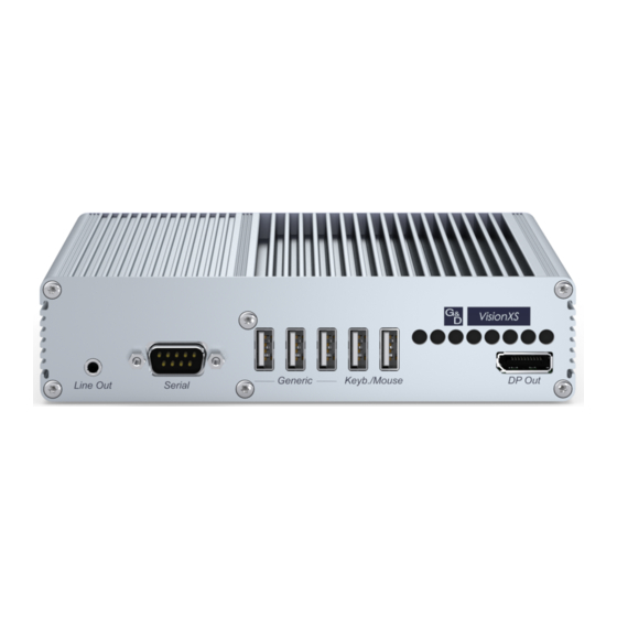
Installation Installation des Arbeitsplatzmoduls An das Arbeitsplatzmodul VisionXS-CON schließen Sie den entfernten Arbeitsplatz an. An diesem Arbeitsplatz können Sie den am Rechnermodul angeschlossenen Rechner bedienen. Verbindung mit einem lokalen Management-Netzwerk herstellen Transmission 1 Transmission 1 Transmission 2 Transmission 2 Service Service Network Pwr Main Power... - Page 18 Installation Monitor des Arbeitsplatzes anschließen Line Out Line Out Serial Serial Generic Generic Keyb./Mouse Keyb./Mouse DP Out Schließen Sie den Monitor des Arbeitsplatzes an. DP Out: Audio- und RS232-Schnittstellen verbinden (modellabhängig) Line Out Serial Generic Generic Keyb./Mouse Keyb./Mouse DP Out DP Out Line Out: Schließen Sie die Lautsprecher oder ein anderes Audioausgabegerät des...
- Page 19 Installation Verbindung mit dem Rechnermodul herstellen Transmission 1 Transmission 2 Transmission 2 Service Service Network Network Pwr Main Power Pwr Main Power Red. Power Red. Power WICHTIG: Das Gerät verwendet Baugruppen mit Laser-Technologie, die der Laser- Klasse 1 entsprechen. Betrachten Sie die unsichtbare Laserstrahlung niemals mit optischen Instrumenten! HINWEIS: Entfernen Sie die Schutzkappen der Transmission-Schnittstellen und der Kabelstecker.
- Page 20 Installation Stromversorgung herstellen HINWEIS: Alle Gerätevarianten der VisionXS -Serie können mit einer externen Span- nungsversorgung an der Power -Schnittstelle (bei Desktop-Gehäusen: Main Power betrieben werden. Die Abbildungen in diesem Kapitel zeigen die Desktop-Variante der Geräteserie. Diese Variante ist zusätzlich mit einem internen Netzteil ( Red.
-
Page 21: Inbetriebnahme
Inbetriebnahme Inbetriebnahme Nach der ordnungsgemäßen Installation der KVM-Extender können diese sofort in Betrieb genommen werden. Beachten Sie folgende Einschaltreihenfolge bei der Erstinbetriebnahme der Module: 1. Schalten Sie die externe Spannungsversorgung des Arbeitsplatzmoduls oder schalten Sie das interne Netzteil (nur Desktop-Variante) ein. 2. -
Page 22: Bedienung
Bedienung Bedienung Den am Rechnermodul angeschlossenen Rechner können Sie am ent- VisionXS-CPU fernten Arbeitsplatz des Arbeitsplatzmoduls bedienen. HINWEIS: Die Freischaltung des kostenpflichtig erhältlichen Transm. Redundancy- Features aktiviert die Transmission 2 -Schnittstelle. Für die Verwendung der -Schnittstelle benötigen Sie einen zusätzli- Transmission 2 chen kostenpflichtig erhältlichen . -
Page 23: Exklusive Bedienung Des Kvm-Extenders
Bedienung Exklusive Bedienung des KVM-Extenders WICHTIG: Die Freischaltung des kostenpflichtig erhältlichen Transm. Redundancy- Features , die Verwendung eines zusätzlichen SFP-Transceivers sowie die Verbindung mit einem zweiten Arbeitsplatzmodul sind Voraussetzung für diese Bedienmög- lichkeit. Um die exklusive Bedienung des KVM-Extenders durch einen Arbeitsplatz zu ermöglichen, kann die Berechtigung für den exklusiven Zugriff des Arbeitsplatzes aktiviert werden. -
Page 24: Erstkonfiguration Der Netzwerkeinstellungen
Erstkonfiguration der Netzwerkeinstellungen Erstkonfiguration der Netzwerk- einstellungen Grundlegende Voraussetzung für den Zugriff auf die Webapplikation des KVM- Extenders ist die Konfiguration der Netzwerkeinstellungen des Rechner- und des Arbeitsplatzmoduls. HINWEIS: Im Auslieferungszustand sind folgende Einstellungen vorausgewählt: IP-Adresse der Netzwerkschnittstelle A: Bezug der Adresse via (Fallback: IP-Adresse 192.168.0.1) DHCP... -
Page 25: Konfiguration Der Globalen Netzwerkeinstellungen
Erstkonfiguration der Netzwerkeinstellungen Netmask: Geben Sie die Netzmaske des Netzwerkes an. Im Betriebsmodus DHCP ist keine Eingabe möglich. 5. Betätigen Sie die -Taste zur Speicherung der durchgeführten Änderungen. Konfiguration der globalen Netzwerkeinstellungen Die globalen Netzwerkeinstellungen stellen auch in komplexen Netzwerken sicher, dass der KVM-Extender aus allen Teilnetzwerken erreichbar ist. -
Page 26: Konfiguration
Konfiguration Konfiguration Die Konfiguration des KVM-Extenders kann wahlweise im On-Screen-Display (OSD) oder über die Webapplikation Config Panel durch den Anwender geändert werden: Das On-Screen-Display wird auf dem Monitor des Arbeitsplatzes angezeigt. Die meisten Konfigurationseinstellungen können Sie im OSD direkt am Arbeitsplatz einstellen. -
Page 27: Bedienung Des On-Screen-Displays Am Arbeitsplatz
Konfiguration Funktion Standardeinstellung Seite Wiederherstellung der Standardeinstellungen Reset der Netzfilterregeln Farbe der Informationseinblendung ändern hellgrün Anzeige der Informationseinblendung temporär Transparenz des On-Screen-Displays einstellen mittleres Durchscheinen Automatisches Schließen des OSD nach Inaktivität deaktiviert Position der Informationseinblendung ändern links oben Position des On-Screen-Displays ändern zentriert Die grundlegende Bedienung des On-Screen-Displays (s. -
Page 28: Aufbau Des On-Screen-Displays
Konfiguration Aufbau des On-Screen-Displays Nach der Ausführung des Hotkeys wird das OSD auf dem Monitor des Arbeitsplat- zes angezeigt: Konfiguration Arbeitsplatzeinrichtung Target-Einrichtung System-Einrichtung Benutzereinrichtung Benutzergruppeneinrichtung ... Netzwerkeinrichtung Information Die Menüansichten des On-Screen-Displays bestehen aus drei Hauptbereichen: Kopfzeile Hier wird der Titel des aktuellen Menüs angezeigt. -
Page 29: Bedienung Des On-Screen-Displays
Konfiguration Bedienung des On-Screen-Displays Das On-Screen-Display wird mit der Tastatur des Arbeitsplatzes bedient. Nachfol- gend finden Sie eine Auflistung der häufig verwendeten Tasten: Pfeiltasten: Mit den Pfeiltasten (in einigen Menüs auch Hoch Runter Links Rechts ) bewegen Sie die Positionsmarke zwischen verschiedenen Menüeinträgen. -
Page 30: Grundlegende Bedienung Der Webapplikation
Konfiguration Grundlegende Bedienung der Webapplikation Die Webapplikation bietet eine grafische Benutzeroberfläche zur Konfigu- Config Panel ration und Überwachung des KVM-Extenders. Die Webapplikation kann unabhängig von den Standorten der am KVM-System angeschlossenen Geräte und Arbeitsplätze im gesamten Netzwerk eingesetzt wer- den. HINWEIS: Grundlegende Informationen zu den Systemvoraussetzungen, der erfor- derlichen Konfiguration der Netzwerkschnittstellen der... -
Page 31: Webapplikation Beenden
Konfiguration Webapplikation beenden Mit der Abmelden-Funktion beenden Sie die aktive Sitzung der Webapplikation. WICHTIG: Verwenden Sie immer die Abmelden-Funktion nach Abschluss Ihrer Arbeit mit der Webapplikation. Die Webapplikation wird so gegen unautorisierten Zugriff geschützt. So beenden Sie die Webapplikation: 1. Klicken Sie auf das Benutzersymbol rechts oben. -
Page 32: Konfigurationseinstellungen
Konfiguration Konfigurationseinstellungen Änderung des Hotkeys Werden auf einem Rechner viele Anwendungsprogramme mit Tastenkombinatio- nen bedient oder verschiedene KVM-Geräte verwendet, ist die Zahl der „freien” Tastenkombinationen möglicherweise eingeschränkt. In solchen Fällen kann der Hotkey geändert werden. HINWEIS: Als Hotkey können Sie eine Taste oder eine Kombination aus den Tasten Strg, Alt, Alt Gr, Win oder Shift wählen. -
Page 33: Änderung Der Osd-Taste
Konfiguration Änderung der OSD-Taste Der Hotkey zum OSD-Aufruf besteht aus mindestens einer Hotkey-Modifizierer- taste (siehe Änderung des Hotkeys auf Seite 27) und einer zusätzlichen OSD-Taste, die vom Anwender innerhalb eines vorgegebenen Rahmens frei gewählt werden kann. Sowohl die Hotkey-Modifizierertaste als auch die OSD-Taste können von Strg Ihnen verändert werden. -
Page 34: On-Screen-Display Mit Doppeltem Tastendruck Starten
Konfiguration On-Screen-Display mit doppeltem Tastendruck starten Alternativ zum Öffnen des On-Screen-Displays (OSD) mit der Tastenkombination bzw. können Sie das OSD durch die zweifache, auf- Hotkey+Num Doppel-Hotkey+Num einanderfolgende Betätigung einer konfigurierten Taste öffnen. So (de)aktivieren Sie die Aktivierung des On-Screen-Displays mit doppeltem Tastendruck: 1. -
Page 35: Änderung Der Exklusivmodus-Aktionstaste
Konfiguration Änderung der Exklusivmodus-Aktionstaste WICHTIG: Die Freischaltung des kostenpflichtig erhältlichen Transm. Redundancy- Features , die Verwendung eines zusätzlichen SFP-Transceivers sowie die Verbindung mit einem zweiten Arbeitsplatzmodul sind Voraussetzung für diese Bedienmög- lichkeit. Nach Betätigung der Tastenkombination für die exklusive Bedienung des Extenders sind die Eingabegeräte des konkurrierenden Arbeitsplatzes deaktiviert. - Page 36 Konfiguration 1. Klicken Sie im Menü auf KVM-Extender 2. Doppelklicken Sie auf das zu konfigurierende Rechnermodul ( 3. Wählen Sie im Feld die gewünschte Taste aus. Exklusivmodus-Aktionstaste Zur Auswahl stehen die Tasten Druck, Rollen, Num, Pause, Einf., Entf., Pos 1, Ende, Bild auf, Bild ab, Leertaste und Backspace.
-
Page 37: Änderung Der Zeitspanne Der Eingabesperre
Konfiguration Änderung der Zeitspanne der Eingabesperre WICHTIG: Die Freischaltung des kostenpflichtig erhältlichen Transm. Redundancy- Features , die Verwendung eines zusätzlichen SFP-Transceivers sowie die Verbindung mit einem zweiten Arbeitsplatzmodul sind Voraussetzung für diese Bedienmög- lichkeit. Wird an einem Arbeitsplatz eine Eingabe per Tastatur oder Maus durchgeführt, sperrt der KVM-Extender automatisch die Eingabegeräte des konkurrierenden Arbeitsplatzes. -
Page 38: Berechtigung Für Exklusiven Zugriff Des Arbeitsplatzes
Konfiguration Berechtigung für exklusiven Zugriff des Arbeitsplatzes WICHTIG: Die Freischaltung des kostenpflichtig erhältlichen Transm. Redundancy- Features , die Verwendung eines zusätzlichen SFP-Transceivers sowie die Verbindung mit einem zweiten Arbeitsplatzmodul sind Voraussetzung für diese Bedienmög- lichkeit. Erfolgt innerhalb der eingestellten Zeitspanne der automatischen Eingabesperre (Standard: 1 Sekunde) keine Eingabe am aktiven Arbeitsplatz, erlaubt der KVM- Extender in der Standardeinstellung auch dem anderen Arbeitsplatz die Bedienung des Extenders. - Page 39 Konfiguration 1. Klicken Sie im Menü auf KVM-Extender 2. Doppelklicken Sie auf das zu konfigurierende Arbeitsplatzmodul CON-Trans 1 bzw. CON-Trans 2 3. Wählen Sie im Feld zwischen folgenden Optionen: Permanent-Access-Modus Berechtigung für exklusiven Zugriff erteilt (Standard) Aktiviert Deaktiviert Berechtigung für exklusiven Zugriff verweigert 4.
-
Page 40: Änderung Der Videobetriebsart Der Arbeitsplätze
Konfiguration Änderung der Videobetriebsart der Arbeitsplätze WICHTIG: Die Freischaltung des kostenpflichtig erhältlichen Transm. Redundancy- Features , die Verwendung eines zusätzlichen SFP-Transceivers sowie die Verbindung mit einem zweiten Arbeitsplatzmodul sind Voraussetzung für diese Bedienmög- lichkeit. In der Standardkonfiguration des KVM-Extenders wird das Bild des Rechners sowohl am Monitor des aktiven als auch am Monitor des konkurrierenden Arbeits- platzes ausgegeben. - Page 41 Konfiguration 1. Klicken Sie im Menü auf KVM-Extender 2. Doppelklicken Sie auf das zu konfigurierende Arbeitsplatzmodul CON-Trans 1 bzw. CON-Trans 2 3. Wählen Sie im Feld zwi- Bildanzeige bei Aktionen am konkurrierenden Arbeitsplatz schen folgenden Optionen: Immer an Das Bild des Rechners wird sowohl am Monitor des aktiven als auch am Monitor des konkurrierenden Arbeitsplatzes ausgegeben (Standard).
-
Page 42: Arbeitsplatzaktivierung Nach Permanenter Ausschaltung Der Bildanzeige
Konfiguration Arbeitsplatzaktivierung nach permanenter Ausschaltung der Bildanzeige WICHTIG: Die Freischaltung des kostenpflichtig erhältlichen Transm. Redundancy- Features , die Verwendung eines zusätzlichen SFP-Transceivers sowie die Verbindung mit einem zweiten Arbeitsplatzmodul sind Voraussetzung für diese Bedienmög- lichkeit. HINWEIS: Diese Funktion kann ausschließlich über die Webapplikation ausge- führt werden. -
Page 43: Aktiver Arbeitsplatz Nach Start Des Extenders
Konfiguration Aktiver Arbeitsplatz nach Start des Extenders WICHTIG: Die Freischaltung des kostenpflichtig erhältlichen Transm. Redundancy- Features , die Verwendung eines zusätzlichen SFP-Transceivers sowie die Verbindung mit einem zweiten Arbeitsplatzmodul sind Voraussetzung für diese Bedienmög- lichkeit. Bei Auswahl der -Option (s. Seite 35 f.) zeigen beide Arbeits- Bildanzeige Permanent aus platzmodule nach einem Neustart des Extenders kein Bild an. -
Page 44: Betriebsmodus Der Rs232-Schnittstelle Einstellen
Konfiguration Betriebsmodus der RS232-Schnittstelle einstellen In der Standardeinstellung des Extenders können Sie jedes RS232 -kompatible Gerät an die optionale RS232-Schnittstelle des Arbeitsplatzmoduls anschließen. Der RS232-Datenstrom wird unverändert zum Rechnermodul übertragen. Für die alternative Übertragung von RS422 -Signalen können Sie zwei G&D RS232-422- Adapter verwenden. - Page 45 Konfiguration 1. Klicken Sie im Menü auf KVM-Extender 2. Doppelklicken Sie auf das zu konfigurierende Modul CON-Trans 1 bzw. CON-Trans 2 3. Wählen Sie im Feld des Abschnitts eine Serielle Kommunikation Konfiguration der folgenden Optionen: RS232 Der Datenstrom eines RS232-Gerätes wird vom Rechnermodul zum Arbeitsplatzmodul übertragen (Standard).
-
Page 46: Auswahl Des Edid-Modus Des Kvm-Extenders
Konfiguration Auswahl des EDID-Modus des KVM-Extenders Die EDID-Informationen (Extended Display Identification Data) eines Monitors infor- mieren die Grafikkarte des angeschlossenen Rechners u. a. über verschiedene techni- sche Eigenschaften des Gerätes. Die Informationen werden vom KVM-Extender üblicherweise unverändert über Enhanced-DDC (Enhanced Display Data Channel) an den Rechner weitergeleitet. - Page 47 Konfiguration 1. Klicken Sie im Menü auf KVM-Extender 2. Doppelklicken Sie auf das zu konfigurierende Rechnermodul ( 3. Klicken Sie auf den Reiter Videokanäle 4. Wählen Sie im Feld des Abschnitts zwischen folgenden EDID-Profil Videokanal Optionen: [Auto] automatische Behandlung der EDID-Daten (Standard) GUD DVI …...
-
Page 48: Reduzierung Der Farbtiefe Der Zu Übertragenden Bilddaten
Konfiguration Reduzierung der Farbtiefe der zu übertragenden Bilddaten In der Standardeinstellung des KVM-Extenders werden die Bildinformationen mit einer maximalen Farbtiefe von 24 bit an das Arbeitsplatzmodul übertragen. Bei Verwendung einer hohen Bildauflösung und Darstellung von Bewegtbildern kann es in Ausnahmefällen vorkommen, dass einige Bilder am Arbeitsplatzmodul „übersprungen“... -
Page 49: Verwendung Des Freeze-Modus
Konfiguration Verwendung des Freeze-Modus Wird die Kabelverbindung zwischen dem Rechner- und dem Arbeitsplatzmodul im laufenden Betrieb unterbrochen, wird in der Standardeinstellung des KVM-Extenders kein Bild auf dem Monitor des entfernten Arbeitsplatzes dargestellt. Aktivieren Sie den Freeze-Modus, wenn Sie im Falle eines Verbindungsabbruchs das zuletzt am Arbeitsplatzmodul empfangene Bild darstellen möchten bis die Verbin- dung wiederhergestellt ist. - Page 50 Konfiguration 1. Klicken Sie im Menü auf KVM-Extender 2. Doppelklicken Sie auf das zu konfigurierende Rechnermodul ( 3. Klicken Sie auf den Reiter Videokanäle 4. Wählen Sie im Feld Freeze-Modus zwischen folgenden Optionen: Kein Bild bei Verbindungsabbruch anzeigen (Standard). An | OSD-Timer + Rahmen ...
-
Page 51: Ddc/Ci-Unterstützung (De)Aktivieren
Konfiguration DDC/CI-Unterstützung (de)aktivieren Die vom -System unterstützten Rechner- und Arbeitsplatzmodule VisionXS-F-DP-UHR wurden vorbereitet, um Monitore mit DDC/CI -Funktion zu unterstützen. DDC/CI -Informationen werden nach Aktivierung der Funktion transparent an den Monitor weitergeleitet, um eine größtmögliche Anzahl an Monitoren zu unterstützen. Die Unterstützung kann jedoch nicht für alle Monitor-Modelle garantiert werden. -
Page 52: Usb-Tastaturmodus Oder "Generic Usb" (De)Aktivieren
Konfiguration USB-Tastaturmodus oder »Generic USB« (de)aktivieren Der KVM-Extender unterstützt verschiedene USB-Eingabegeräte. Die besonderen Eigenschaften eines bestimmten USB-Eingabegerätes können Sie nach Auswahl des spezifischen USB-Tastaturmodus nutzen. Alternativ zu dem spezifischen USB-Tastaturmodus können Sie den Generic-USB Modus nutzen. In diesem Modus werden die Daten des USB-Gerätes an der ober- sten -Buchse des Arbeitsplatzmoduls unverändert an das Rechnermodul Keyb./Mouse... - Page 53 Konfiguration Generic-USB-Modus: In diesem Modus werden die Daten des USB-Gerätes an der obersten Keyb./Mouse -Buchse des Arbeitsplatzmoduls unverändert an das Rechner- modul übertragen. EINGABEGERÄT EINSTELLUNG beliebiger USB-Massenspeicher oder beliebiges USB-Eingabegerät Generic USB WICHTIG: Generic-USB -Modus unterstützt viele der am Markt erhältlichen USB-Massenspeichergeräte und -Eingabegeräte.
-
Page 54: Änderung Des Scancode-Sets Einer Ps/2-Tastatur
Konfiguration Änderung des Scancode-Sets einer PS/2-Tastatur Wird eine Taste der PS/2-Tastatur gedrückt, sendet der Tastaturprozessor ein Datenpaket, das als Scancode bezeichnet wird. Es gibt zwei gebräuchliche Scan- code-Sets (Sets 2 und 3), die verschiedene Scancodes beinhalten. Der KVM-Extender interpretiert in der Standardeinstellung alle Eingaben einer PS/2- Tastatur mit dem Scancode-Set 2. -
Page 55: Reinitialisierung Von Usb-Eingabegeräten
Konfiguration Reinitialisierung von USB-Eingabegeräten Sobald Sie eine USB-Tastatur bzw. -Maus an den KVM-Extender anschließen, wird das Eingabegerät initialisiert und kann ohne Einschränkungen verwendet werden. Einige USB-Eingabegeräte erfordern eine Reinitialisierung der USB-Verbindung nach einer bestimmten Zeit. Aktivieren Sie die automatische Reinitialisierung der USB-Eingabegeräte, falls eine USB-Tastatur oder -Maus im laufenden Betrieb nicht mehr auf Ihre Eingaben reagiert. - Page 56 Konfiguration 1. Klicken Sie im Menü auf KVM-Extender 2. Doppelklicken Sie auf das zu konfigurierende Arbeitsplatzmodul CON-Trans 1 bzw. CON-Trans 2 3. Wählen Sie im Feld des Abschnitts eine der fol- USB-Auto-Refresh Konfiguration genden Optionen: Der Status der USB-Geräte wird überwacht. Falls Nur fehlerhafte Geräte die Kommunikation zu einem USB-Gerät gestört ist, wird dieses Gerät reinitialisiert (Standard).
-
Page 57: Wartezeit Des Bildschirmschoners Einstellen
Konfiguration Wartezeit des Bildschirmschoners einstellen Der Bildschirmschoner schaltet nach einer von Ihnen einstellbaren Zeit der Inaktivi- tät des Benutzers die Bildschirmanzeige am Arbeitsplatz ab. HINWEIS: Diese Einstellung ist unabhängig von den Bildschirmschoner-Einstel- lungen des am Rechnermodul angeschlossenen Rechners. So stellen Sie die Wartezeit des Bildschirmschoners ein: 1. -
Page 58: Tastaturlayout Für Eingaben Innerhalb Des Osds Auswählen
Konfiguration Tastaturlayout für Eingaben innerhalb des OSDs auswählen Werden bei der Eingabe von Zeichen auf der Tastatur des Arbeitsplatzes andere Zeichen im On-Screen-Display angezeigt, ist das eingestellte Tastaturlayout der Tastatur nicht zutreffend. Stellen Sie in diesem Fall fest, welchem Tastaturlayout die angeschlossene Tastatur entspricht und konfigurieren Sie dieses anschließend in den Einstellungen des Arbeitsplatzmoduls. -
Page 59: Wiederherstellung Der Standardeinstellungen
Konfiguration Wiederherstellung der Standardeinstellungen Mit dieser Funktion werden die Standardeinstellungen des KVM-Extender-Systems wiederhergestellt. Nach dem Ausführen der Funktion sind die auf Seite 21 aufge- führten Standardeinstellungen wieder aktiv. So stellen Sie die Standardeinstellungen wieder her: HINWEIS: Öffnen Sie das lokale OSD des Arbeitsplatzmoduls mit dem lokalen Hot- (Standard: ), falls Sie statt den Einstellungen des Extender-Systems... -
Page 60: Reset Der Netzfilterregeln
Konfiguration Reset der Netzfilterregeln Im Auslieferungszustand des KVM-Extenders haben alle Netzwerk-Rechner Zugriff auf die IP-Adresse des Systems (offener Systemzugang). Über die Webapplikation Config Panel können Sie Netzfilterregeln erstellen, um den Zugang gezielt zu kontrollieren. Sobald eine Netzfilterregel erstellt ist, wird der offene Systemzugang deaktiviert und alle eingehenden Datenpakete mit den Netzfil- terregeln verglichen. -
Page 61: Farbe Der Informationseinblendung Ändern
Konfiguration Farbe der Informationseinblendung ändern Informationseinblendungen werden standardmäßig in hellgrün angezeigt. Im per- sönlichen Profil können Sie die Farbe dieser Einblendungen anpassen. Folgende Farben werden unterstützt: schwarz dunkelrot grün dunkelgelb dunkelblau violett dunkeltürkis silber hellgrün gelb blau magenta helltürkis weiß So ändern Sie die Einstellung der Informationseinblendung: 1. -
Page 62: Anzeige Der Informationseinblendung
Konfiguration Anzeige der Informationseinblendung Informationseinblendungen erfolgen temporär (5 Sekunden) in der linken, oberen Ecke. Alternativ zur temporären Einblendung kann die Informationseinblendung permanent erfolgen oder ausgeschaltet werden. So ändern Sie die Einstellung der Informationseinblendung: 1. Starten Sie das On-Screen-Display mit dem Hotkey Strg+Num (Standard). -
Page 63: Transparenz Des On-Screen-Displays Einstellen
Konfiguration Transparenz des On-Screen-Displays einstellen In der Standardeinstellung wird das On-Screen-Display (OSD) mit einer mittleren Transparenz über dem Bildschirminhalt angezeigt. Den durch das OSD überlager- ten Teil des Bildschirminhalts können Sie „durch“ das OSD erkennen. Die Transparenzstufe können Sie einstellen oder ausschalten. So stellen Sie die Transparenzstufe des On-Screen-Displays ein: 1. -
Page 64: Automatisches Schließen Des Osd Nach Inaktivität
Konfiguration Automatisches Schließen des OSD nach Inaktivität Falls gewünscht, können Sie einstellen, dass das OSD automatisch nach Ablauf einer Zeitspanne der Inaktivität geschlossen wird. Den Zeitraum der Inaktivität können Sie im Bereich von Sekunden festlegen. HINWEIS: Zum Deaktivieren der Funktion geben Sie die Ziffer ein. -
Page 65: Position Der Informationseinblendung Ändern
Konfiguration Position der Informationseinblendung ändern HINWEIS: Diese Funktion kann ausschließlich über das On-Screen-Display ausge- führt werden. In der Standardeinstellung erfolgen die Informationseinblendungen links oben auf dem Bildschirm des Arbeitsplatzes. Die Position der Einblendung können Sie nach Ihren Wünschen anpassen. So ändern Sie die Position der Informationseinblendung: 1. -
Page 66: Position Des On-Screen-Displays Ändern
Konfiguration Position des On-Screen-Displays ändern HINWEIS: Diese Funktion kann ausschließlich über das On-Screen-Display ausge- führt werden. Das On-Screen-Display wird in der Standardeinstellung zentriert auf dem Bild- schirm des Arbeitsplatzes dargestellt. Die OSD-Position können Sie nach Ihren Wünschen anpassen. So ändern Sie die Position des On-Screen-Displays: 1. -
Page 67: Weiterführende Informationen
Weiterführende Informationen Weiterführende Informationen DDC-Weiterleitung mit Cache-Funktion Der KVM-Extender unterstützt Enhanced-DDC (Enhanced Display Data Channel), um die Eigenschaften des am Arbeitsplatzmoduls angeschlossenen Monitors auszu- lesen und an den Rechner weiterzuleiten. Diese Eigenschaften umfassen beispiels- weise Informationen über die bevorzugte Auflösung und die unterstützten Frequenzen des Monitors. -
Page 68: Pin-Belegung Der Rs232-Buchse/Schnittstelle
Weiterführende Informationen Pin-Belegung der RS232-Buchse/Schnittstelle Die Pin-Belegungen des RS232-Steckers sowie der -Buchse zeigen die folgenden Abbildungen: Arbeitsplatzmodul Rechnermodul RS232-Stecker RS232-Buchse Die Tabelle zeigt die Zuordnung der verschiedenen Leitungen der Datenverbindung zu den entsprechenden Pins auf: Pin-Nr. Leitung Arbeitsplatz- Rechner- modul modul nicht belegt RxD (Receive Data) -
Page 69: Statusanzeigen
Statusanzeigen Statusanzeigen Die LEDs an der Rückseiten des Rechner- und des Arbeitsplatzmoduls geben Ihnen die Möglichkeit, den Betriebsstatus des KVM-Extenders jederzeit zu kontrollieren. Transmission 1 Transmission 2 Service Network Main Power Main Power Red. Power Red. Power Farbe Status Bedeutung Trans- grün Eine G&D Gegenstelle ist aufgeschaltet. -
Page 70: Technische Daten
Technische Daten Technische Daten Allgemeine Eigenschaften der Serie VISIONXS-F-DP-UHR-SERIE Schnittstellen für Video: siehe spezifische Eigenschaften Rechner USB-Tastatur/Maus: 1 × USB-B-Buchse Audio: 3,5-mm-Klinkenbuchse (Line In) Varianten [A] und [AR] RS232: 1 × RS232-Buchse (Serial) Varianten [A] und [AR] Schnittstellen für Monitor: ... - Page 71 Technische Daten VISIONXS-F-DP-UHR-SERIE USB 2.0 Full Speed Spezifikation: USB 2.0 Variante [U] Übertragungsart transparent Übertragungsrate max. 16 Mbit/s Unterstützte Geräte: High-Power-Devices (bis 500 mA) Grafik Format: DisplayPort (DP 1.2a) Farbtiefe: 24 Bit Pixelkodierung: RGB 4:4:4 mit 24bpp/8bpc Videobandbreite: max. 600 MP / s, DisplayPort 4 Lanes, LBR, HBR, HBR2, SingleStreamTransport (SST) max.
-
Page 72: Spezifische Eigenschaften Der Geräte
Technische Daten Spezifische Eigenschaften der Geräte VISIONXS-CPU-F-DP-UHR Schnittstelle für Video: 1 × DisplayPort-Buchse Rechner Schnittstelle zur KVM, Audio und RS232: 1 [+1 optional] × LC-Duplex-Buchse Gegenstelle Stromaufnahme Hauptstromversorgung: 12 VDC/1,5 A Gehäuse Material: Aluminium eloxiert Dimensionen (B × H × T): 109 ×... - Page 73 Technische Daten VISIONXS-CPU-F-DP-UHR-U Schnittstelle für Video: 1 × DisplayPort-Buchse Rechner Schnittstelle zur KVM, Audio und RS232: 1 [+1 optional] × LC-Duplex-Buchse Gegenstelle Stromaufnahme Hauptstromversorgung: 12 VDC/1,5 A Gehäuse Material: Aluminium eloxiert Dimensionen (B × H × T): 109 × 39,8 × 184 mm Gewicht: ca.
- Page 74 Technische Daten VISIONXS-CPU-F-DP-UHR-DT Schnittstelle für Video: 1 × DisplayPort-Buchse Rechner Schnittstelle zur KVM, Audio und RS232: 1 [+1 optional] × LC-Duplex-Buchse Gegenstelle Stromaufnahme Hauptstromversorgung: 12 VDC/1,5 A redundante 100-240 VAC/60-50Hz/0,5-0,3 A Stromversorgung Gehäuse Material: Aluminium eloxiert Dimensionen (B × H × T): 170 ×...
- Page 75 Technische Daten VISIONXS-CPU-F-DP-UHR-U-DT Schnittstelle für Video: 1 × DisplayPort-Buchse Rechner Schnittstelle zur KVM, Audio und RS232: 1 [+1 optional] × LC-Duplex-Buchse Gegenstelle Stromaufnahme Hauptstromversorgung: 12 VDC/1,5 A redundante 100-240 VAC/60-50Hz/0,5-0,3 A Stromversorgung Gehäuse Material: Aluminium eloxiert Dimensionen (B × H × T): 170 ×...
- Page 76 Technische Daten VISIONXS-CPU-F-DP-UHR-AR-DT Schnittstelle für Video: 1 × DisplayPort-Buchse Rechner Schnittstelle zur KVM, Audio und RS232: 1 [+1 optional] × LC-Duplex-Buchse Gegenstelle Stromaufnahme Hauptstromversorgung: 12 VDC/1,5 A redundante 100-240 VAC/60-50Hz/0,5-0,3 A Stromversorgung Gehäuse Material: Aluminium eloxiert Dimensionen (B × H × T): 170 ×...
- Page 77 Technische Daten VISIONXS-CPU-F-DP-UHR-AR-U-DT Schnittstelle für Video: 1 × DisplayPort-Buchse Rechner Schnittstelle zur KVM, Audio und RS232: 1 [+1 optional] × LC-Duplex-Buchse Gegenstelle Stromaufnahme Hauptstromversorgung: 12 VDC/1,5 A redundante 100-240 VAC/60-50Hz/0,5-0,3 A Stromversorgung Gehäuse Material: Aluminium eloxiert Dimensionen (B × H × T): 170 ×...
- Page 78 Technische Daten VISIONXS-CPU-F-DP-UHR-A Schnittstelle für Video: 1 × DisplayPort-Buchse Rechner Schnittstelle zur KVM, Audio und RS232: 1 [+1 optional] × LC-Duplex-Buchse Gegenstelle Stromaufnahme Hauptstromversorgung: 12 VDC/1,5 A Gehäuse Material: Aluminium eloxiert Dimensionen (B × H × T): 109 × 39,8 × 184 mm Gewicht: ca.
-
Page 79: Eigenschaften Der Übertragungsmodule
Technische Daten Eigenschaften der Übertragungsmodule MULTIMODE-ÜBERTRAGUNGSMODUL Datenübertragung Art: Lichtwellenleiter (2 Glasfasern) Schnittstellentyp: LC-Duplex Kabellänge (max.) Multimode 50/125μm, 400 Meter (Fasern mit 4700MHz*km) Klasse OM4: Multimode 50/125μm, 400 Meter (Fasern mit 2000MHz*km) Klasse OM3: Multimode 50/125μm, 200 Meter (Fasern mit 500MHz*km) Klasse OM2: Multimode 50/125μm: 150 Meter (Fasern mit 400MHz*km) - Page 82 About this manual This manual has been carefully compiled and examined to the state-of-the-art. G&D neither explicitly nor implicitly takes guarantee or responsibility for the qual- ity, efficiency and marketability of the product when used for a certain purpose that differs from the scope of service covered by this manual.
- Page 83 FCC Statement The devices named in this manual comply with Part 15 of the FCC Rules. Opera- tion is subject to the following two conditions: (1) the devices may not cause harm- ful interference, and (2) the devices must accept any interference received, including interference that may cause undesired operation.
- Page 84 Table of contents Table of contents Safety guidelines ....................1 The VisionXS-F-DP-UHR series ..............5 Optional connection to a KVM matrix switch ............. 5 Package contents ....................6 Installation ....................... 7 Preparation ......................7 Installing the computer module ................8 Installing user modules ..................
- Page 85 Table of contents Configuration settings (continued)................Enabling or disabling DDC/CI support ............45 (De)Activating an USB keyboard or the »Generic USB« mode ....46 Changing the scancode set of PS/2 keyboards ..........48 Reinitialising USB input devices ..............49 Adjusting the waiting period of the screensaver ........... 51 Selecting a keyboard layout for inputs via OSD ..........
-
Page 86: Safety Guidelines
Safety guidelines Safety guidelines Please read through the following safety guidelines before putting the G&D product into operation. The guidelines help to avoid damage to the product and prevent potential injuries. Keep these safety guidelines ready to hand for all persons who use this product. Observe all warnings and operating information given at the device or in this operat- ing manual. - Page 87 Safety guidelines Ensure correct installation position for devices with ventilation openings For reasons of electric safety, devices with ventilation openings must only be installed in an upright, horizontal position. Do not insert any objects through the device’s openings Objects should never be inserted through the device’s openings. Dangerous voltage could be present.
- Page 88 Safety guidelines Instructions on how to handle Lithium button cells This product contains a lithium button cell. It is not intended to be replaced by the user! CAUTION: Risk of explosion if the battery is replaced by an incorrect battery type. Dispose of used batteries in an environmentally friendly manner.
- Page 89 Safety guidelines Special advices for dealing with laser technology The devices of the VisionXS-F-DP-UHR series use components with laser technology which comply with laser class 1 or better. They meet the requirements according to EN 60825-1:2014 as well as U.S. CFR 1040.10 1040.11 Invisible laser beam, avoid Class 1 Laser Product...
-
Page 90: The Visionxs-F-Dp-Uhr Series
The VisionXS-F-DP-UHR series The VisionXS-F-DP-UHR series KVM extenders of the series consist of a computer module and a VisionXS-F-DP-UHR user modules. Connect the computer to be operated to the computer module ( ). The VisionXS-CPU remote console is connected to the user module (... -
Page 91: Package Contents
Package contents Package contents Standard package contents 1 × computer module ( VisionXS-CPU 1 × user module ( VisionXS-CON 1 × video cable (DP-Cable-M/M-2) 1 × USB device cable (USB-AM/BM-2) 1 × service cable (2Micro-USB-Service-2) ... -
Page 92: Installation
Installation Installation IMPORTANT: The devices use components with laser technology which comply with laser class 1. They meet the requirements in accordance to EN 60825-1:2014 as well as U.S. CFR 1040.10 1040.11 Consider the following safety guidelines regarding this matter: ... -
Page 93: Installing The Computer Module
Installation Installing the computer module NOTE: All device variants of the series can be operated with an external VisionXS power supply at the Power interface (for desktop casings: Main Power The illustrations in this chapter show the desktop variant of the device series. This variant is additionally equipped with an internal power supply ( Red. - Page 94 Installation Connecting audio and RS232 interfaces (depending on model) Line In Serial USB CPU USB CPU DP CPU DP CPU NOTE: By default, the KVM system transfers audio data between user and com- puter module. In addition, you can enable the transmission of RS232 data (see Adjusting the operating mode of the RS232 interface on page 39).
- Page 95 Installation Establishing a connection to the user module Transmission 1 Transmission 2 Transmission 2 Service Service Network Network Pwr Main Power Pwr Main Power Red. Power Red. Power IMPORTANT: The devices use components with laser technology which comply with laser class 1. Never stare directly into the beam when wearing optical instruments! NOTE: Remove the protection caps from the Transmission interfaces and from the...
- Page 96 Installation Establishing the power supply NOTE: All device variants of the VisionXS series can be operated with an external power supply at the Power interface (for desktop casings: Main Power The illustrations in this chapter show the desktop variant of the device series. This variant is additionally equipped with an internal power supply ( Red.
-
Page 97: Installing User Modules
Installation Installing user modules The remote console is connected to the VisionXS-CON user module. The computer connected to the computer module can be operated from this console. Establishing a connection to a local management network Transmission 1 Transmission 1 Transmission 2 Transmission 2 Service Service... - Page 98 Installation Connecting the console monitor Line Out Line Out Serial Serial Generic Generic Keyb./Mouse Keyb./Mouse DP Out Connect the console monitor. DP Out: Connecting audio and RS232 interfaces (depending on model) Line Out Serial Generic Generic Keyb./Mouse Keyb./Mouse DP Out DP Out Line Out: Connect the speakers or another audio output device.
- Page 99 Installation Establishing a connection to the computer module Transmission 1 Transmission 2 Transmission 2 Service Service Network Network Pwr Main Power Pwr Main Power Red. Power Red. Power IMPORTANT: The device uses components with laser technology which comply with laser class 1. Never stare directly into the beam when wearing optical instruments! NOTE: Remove the protection caps from the Transmission interfaces and the cable...
- Page 100 Installation Establishing the power supply NOTE: All device variants of the VisionXS series can be operated with an external power supply at the Power interface (for desktop casings: Main Power The illustrations in this chapter show the desktop variant of the device series. This variant is additionally equipped with an internal power supply ( Red.
-
Page 101: Start-Up
Start-up Start-up After the proper installation of the KVM extenders they can be immediately put into operation. Mind the following activation sequence when starting the modules: 1. Switch on the external power supply of the user module or switch on the internal power supply (desktop variant only). 2. -
Page 102: Operation
Operation Operation You can operate the computer connected to the computer module at VisionXS-CPU the remote console of the user module. NOTE: The activation of the Transm. Redundancy feature activates the Transmission 2 interface. To use the Transmission 2 interface, you need an additional SFP transceiver. Choose the right SFP transceiver for your variant of the... -
Page 103: Operating The Kvm Extender Exclusively
Operation Operating the KVM extender exclusively IMPORTANT: The activation of the , an additional Transm. Redundancy feature SFP tran- sceiver and the connection to a second user module are prerequisites for this oper- ation option. Activate the right for permanent access to operate the KVM extender exclusively with one console. -
Page 104: Initial Configuration Of The Network Settings
Initial configuration of the network settings Initial configuration of the network settings A basic requirement to access the web application of the KVM extender is the con- figuration of the network settings of the computer module and the user module. NOTE: In the default settings the following settings are preselected: ... -
Page 105: Configuring Global Network Settings
Initial configuration of the network settings Netmask: Enter the netmask of the network. The operational mode DHCP does not allow making entries. 5. Press to save your settings. Configuring global network settings Even in complex networks global network settings ensure that the KVM extender is available from all partial networks. -
Page 106: Configuration
Configuration Configuration The configuration of the KVM extender can be changed either using the on-screen display (OSD) or the web application Config Panel The on-screen display is shown on the console monitor. Most configuration settings can be changed directly on the OSD of the console. ... -
Page 107: Operating The On-Screen Display At The Console
Configuration Function Default setting Page Resetting the default settings Resetting the netfilter rules Changing the colour of the information display light green Information display temporarily Adjusting the transparency of the on-screen display average transparency Automatic closing of the OSD after inactivity deactivated Changing the position of the information dispaly left upper corner... -
Page 108: Layout Of The On-Screen Display
Configuration Layout of the on-screen display After pressing the hotkeys, the OSD is displayed on the console monitor: Configuration Console setup Target setup System setup User setup User group setup Network setup Information The on-screen display consists of three parts: Header ... -
Page 109: Operating The On-Screen Display
Configuration Operating the on-screen display The on-screen display is operated with the console keyboard. The following table shows you a list of frequently used keys: Arrow keys: Press the arrow keys Down (in some menus also Left Right ) to move the cursor between the different menu items. Enter: Use this key to confirm inputs of open a submenu. -
Page 110: Basic Operation Of The Web Application
Configuration Basic operation of the web application web application provides a graphical user interface to configure and Config Panel monitor the KVM extender. The web application can be used in the entire network independently from the loca- tions of the devices and consoles connected to the KVM system. NOTE: The separate manual provides information about system requirements, the required configuration of the network interfaces at the... -
Page 111: Closing The Web Application
Configuration Closing the web application Use the Close button to end the active session of the web application. IMPORTANT: To protect the web application against unauthorised access, always use the Logout function after finishing your work with the web application. How to close the web application: 1. -
Page 112: Configuration Settings
Configuration Configuration settings Changing hotkeys If many applications that use hotkeys are operated on one computer or if different KVM devices are used, the number of available hotkeys might be restricted. In this case the hotkey can be changed. NOTE: Select your desired key or key combination from the keys Ctrl, Alt, Alt Gr, Win or Shift. -
Page 113: Changing The Osd Key
Configuration Changing the OSD key The hotkey to open the OSD consists of at least one hotkey modifier (see Changing hotkeys on page 27) and an additional OSD key. You can freely select these keys from a number of selectable keys. You can change both the hotkey modifier and the OSD key Ctrl... -
Page 114: Opening The On-Screen Display Via Double Keypress
Configuration Opening the on-screen display via double keypress As an alternative to opening the on-screen display (OSD) with the hotkey Hot- you can also open the OSD by pressing a configured key+Num Double hotkey+Num key twice. How to enable/disable the activation of the on-screen display via double key- press: 1. -
Page 115: Changing The Exclusive Mode Aktionkey
Configuration Changing the exclusive mode aktionkey IMPORTANT: The activation of the , an additional Transm. Redundancy feature SFP tran- sceiver and the connection to a second user module are prerequisites for this oper- ation option. After pressing the hotkey for the exclusive operation of the extender the input devices of the concurrent console are disabled. - Page 116 Configuration 1. In the menu, click on KVM extender 2. Click twice on the computer module ( ) you want to configure. 3. Under select one of the following keys: Exclusive mode actionkey Backspace, PrtSc, Scroll, Num, Pause, Insert, Delete, Home, End, Page Up, Page Down and Space.
-
Page 117: Changing The Time Span Of The Input Lock
Configuration Changing the time span of the input lock IMPORTANT: The activation of the , an additional Transm. Redundancy feature SFP tran- sceiver and the connection to a second user module are prerequisites for this oper- ation option. When carrying out keyboard or mouse inputs at a console, the KVM extender auto- matically locks the input devices of the concurrent console. -
Page 118: Right For Exclusive Access To The Console
Configuration Right for exclusive access to the console IMPORTANT: The activation of the Transm. Redundancy feature , an additional SFP tran- and the connection to a second user module are prerequisites for this oper- sceiver ation option. If no inputs are made at the active console during the adjusted time span of the auto- matic input lock (default: 1 second), the default settings of the KVM extender permit the other console to operate the extender. - Page 119 Configuration 1. In the menu, click on KVM extender 2. Click twice on the user module ( CON-Trans 1 CON-Trans 2 ) you want to con- figure. 3. Under select one of the following options: Permanent Access mode Enabled right for exclusive access is granted (default) Disabled ...
-
Page 120: Changing The Video Mode Of Consoles
Configuration Changing the video mode of consoles IMPORTANT: The activation of the Transm. Redundancy feature , an additional SFP tran- and the connection to a second user module are prerequisites for this oper- sceiver ation option. In the standard configuration of the KVM extender, the computer’s image is output at the monitor of the active console as well as at the monitor of the concurrent console. - Page 121 Configuration 1. In the menu, click on KVM extender 2. Click twice on the user module ( CON-Trans 1 CON-Trans 2 ) you want to con- figure. 3. Under select one of the follow- Image display during actions at concurrent console ing options: Always on ...
-
Page 122: Activating A Console After The Permanent Switch-Off Of The Image Display
Configuration Activating a console after the permanent switch-off of the image display IMPORTANT: The activation of the Transm. Redundancy feature , an additional SFP tran- sceiver and the connection to a second user module are prerequisites for this oper- ation option. NOTE: This function can be carried out only via web application. -
Page 123: Active Console After Starting An Extender
Configuration Active console after starting an extender IMPORTANT: The activation of the , an additional Transm. Redundancy feature SFP tran- sceiver and the connection to a second user module are prerequisites for this oper- ation option. When selecting the Image display option keep off Permanently off... -
Page 124: Adjusting The Operating Mode Of The Rs232 Interface
Configuration Adjusting the operating mode of the RS232 interface In the default setting of the extender, you can connect any RS232-compatible device to the optional RS232 interface of the console module. The RS232 data stream is transmitted unchanged to the computer module. For transmitting RS422 signals, you can use two G&D RS232-422 adapters . - Page 125 Configuration 1. In the menu, click on KVM extender 2. Click twice on the module you want to configure. CON-Trans 1 CON-Trans 2 3. Select one of the options of the field under the para- Serial communication graph Configuration RS232 ...
-
Page 126: Selecting The Edid Mode Of The Kvm Extender
Configuration Selecting the EDID mode of the KVM extender EDID information (Extended Display Identification Data) of a monitor informs the gra- phics card of a connected computer about different technical device features. The information is usually transmitted via Enhanced-DDC (Enhanced Display Data Chan- nel) and without any alteration between KVM extender and computer. - Page 127 Configuration 1. In the menu, click on KVM extender 2. Click twice on the computer module ( ) you want to configure. 3. Click on the tab Video channels 4. In the field of the section, select between the follow- EDID profile Video channel ing options:...
-
Page 128: Reducing The Colour Depth Of The Image Data To Be Transmitted
Configuration Reducing the colour depth of the image data to be transmitted In the default settings, the KVM extender transmits the image information with a maximum colour depth of 24 bit to the user module. Using a high resolution and displaying moving images can result in the user module “skipping”... -
Page 129: Freeze Mode
Configuration Freeze mode If the cable connection between the computer module and the user module is inter- rupted during operation, the KVM extender no longer displays an image at the remote console. Enable the Freeze mode if you want the last image that has been displayed at the user module to be available until the connection is re-established. -
Page 130: Enabling Or Disabling Ddc/Ci Support
Configuration Enabling or disabling DDC/CI support The computer and user modules supported by the VisionXS-F-DP-UHR system are ready to support monitors with functionality. DDC/CI After the function has been activated, the DDC/CI information is transparently for- warded to the monitor in order to support as many monitors as possible. However, we cannot guarantee the support for all monitors. -
Page 131: (De)Activating An Usb Keyboard Or The "Generic Usb" Mode
Configuration (De)Activating an USB keyboard or the »Generic USB« mode The KVM extender supports various USB input devices. You can use the special fea- tures of a particular USB input device after selecting the specific USB keyboard mode. As an alternative to the specific USB keyboard modes, you can also use the generic mode. - Page 132 Configuration Generic-USB mode: In this mode, data of the USB device connected to the top Keyb./ Mouse socket of the user module is transmitted to the computer module without being altered. INPUT DEVICE SETTING any USB mass storage or USB HID device Generic USB ...
-
Page 133: Changing The Scancode Set Of Ps/2 Keyboards
Configuration Changing the scancode set of PS/2 keyboards If you press a key at the PS/2 keyboard, the keyboard processor sends a data packet that is called scan code. The two common scancode sets (sets 2 and 3) contain differ- ent scancodes. -
Page 134: Reinitialising Usb Input Devices
Configuration Reinitialising USB input devices Once you connect a USB keyboard or mouse to the KVM extender, the input device is initialised and can be used without restrictions. The USB connection of some USB input devices needs to be reinitialised after a cer- tain time. - Page 135 Configuration 1. In the menu, click on KVM extender 2. Click twice on the user module ( CON-Trans 1 CON-Trans 2 ) you want to con- figure. 3. In the field of the section, select one of the fol- USB auto refresh Configuration lowing options: Only faulty devices...
-
Page 136: Adjusting The Waiting Period Of The Screensaver
Configuration Adjusting the waiting period of the screensaver The screensaver turns off the display of the console after the user has been inactive for a defined period of time. NOTE: This setting does not affect the screensaver settings of the computer con- nected to the computer module. -
Page 137: Selecting A Keyboard Layout For Inputs Via Osd
Configuration Selecting a keyboard layout for inputs via OSD If the on-screen display shows other characters than entered on the console key- board, the keyboard layout has to be adjusted. Make sure which keyboard layout the connected keyboard uses and configure it in the settings of the user module. -
Page 138: Resetting The Default Settings
Configuration Resetting the default settings This function is used to reset the default settings of the KVM extender. By perform- ing this function, the default settings mentioned on page 21 are reactivated. How to reset the default settings: NOTE: Open the local OSD of the user module by pressing the local hotkey (default: ) if you want to reset the local settings of the user module only instead of... -
Page 139: Resetting The Netfilter Rules
Configuration Resetting the netfilter rules In the default settings, all network computers can access the system’s IP address (open system access). With the Config Panel web application, you can create netfilter rules to control the access. After a netfilter rule has been created, the open system access is deactivated and all incoming data packets are compared to the netfilter rules. -
Page 140: Changing The Colour Of The Information Display
Configuration Changing the colour of the information display By default, information display are shown in light green. You can adjust the colour of the information display in your personal profile. The following colours are supported: dark red black green dark yellow dark blue purple dark turquoise... -
Page 141: Information Display
Configuration Information display Information displays are shown temporarily (5 seconds) in the upper left corner. The information display can also be shown permanently or it can be disabled. How to change the setting of the information display: 1. Press (default) to open the on-screen display. Ctrl+Num 2. -
Page 142: Adjusting The Transparency Of The On-Screen Display
Configuration Adjusting the transparency of the on-screen display In the default settings of the KVM switch, the on-screen display covers parts of the screen content. However, the parts of the screen contents covered by the OSD are still visible. You can adjust the transparency level or turn the transparency off. How to adjust the transparency of the on-screen display: 1. -
Page 143: Automatic Closing Of The Osd After Inactivity
Configuration Automatic closing of the OSD after inactivity If desired, you can set the OSD to close automatically after a period of inactivity. The period of inactivity can be defined by entering a value between seconds. NOTE: To disable the function, enter the value How to change the period of inactivity after which the OSD closes: 1. -
Page 144: Changing The Position Of The Information Dispaly
Configuration Changing the position of the information dispaly NOTE: This function can be carried out only via on-screen display. In the default configuration, the information display is shown at the left upper cor- ner of the console monitor. However, you can adjust the position to your liking. How to change the position of the information display: 1. -
Page 145: Changing The Position Of The On-Screen Display
Configuration Changing the position of the on-screen display NOTE: This function can be carried out only via on-screen display. By default, the on-screen display is shown at the centre of the console monitor. You can adjust the position to your liking. How to change the position of the on-screen displays: 1. -
Page 146: Further Information
Further information Further information DDC transmission with cache function The KVM extender supports Enhanced-DDC (Enhanced Display Data Channel) to read out the data from the monitor that is connected to the user module and transmit them to the computer. This data includes information regarding the preferred reso- lution and the supported monitor frequencies. -
Page 147: Pin Assignment Of The Rs232 Socket/Interface
Further information Pin assignment of the RS232 socket/interface The following figures show the pin assignments of the RS232 plug as well as the RS 232 socket: User module Computer module RS232 plug RS232 socket The table shows how the different lines of the data connection are assigned to the according pins: Pin no. -
Page 148: Status Leds
Status LEDs Status LEDs The LEDs on the back panel of the computer module and the user module let you control the operational status of the KVM extender at any time. Transmission 1 Transmission 2 Service Network Main Power Main Power Red. -
Page 149: Technical Data
Technical data Technical data General features of the series VISIONXS-F-DP-UHR SERIES Interfaces for Video: see specific features computers USB keyboard/mouse: 1 × USB-B socket Audio: 3.5-mm jack plug (Line In) Variants [A] and [AR] RS232: 1 × RS232 socket (Serial) ... - Page 150 Technical data VISIONXS-F-DP-UHR SERIES USB 2.0 Full Speed Specification: USB 2.0 Variant [U] Transmission type transparent Transmission rate max. 16 Mbit/s Supported devices high-power devices (up to 500 mA) Graphics Format: DisplayPort (DP 1.2a) Colour depth: 24 Bit Pixel encoding:...
-
Page 151: Specific Features Of Devices
Technical data Specific features of devices VISIONXS-CPU-F-DP-UHR Interface for Video: 1 × DisplayPort jack computer Interface to KVM, Audio and RS232: 1 [+1 optional] × LC duplex socket counterpart station Current consumption Main power supply: 12 VDC/1.5 A Casing Material: anodised aluminium Dimensions (W ×... - Page 152 Technical data VISIONXS-CPU-F-DP-UHR-U Interface for Video: 1 × DisplayPort jack computer Interface to KVM, Audio and RS232: 1 [+1 optional] × LC duplex socket counterpart station Current consumption Main power supply: 12 VDC/1.5 A Casing Material: anodised aluminium Dimensions (W × H × D): 109 ×...
- Page 153 Technical data VISIONXS-CPU-F-DP-UHR-DT Interface for Video: 1 × DisplayPort jack computer Interface to KVM, Audio and RS232: 1 [+1 optional] × LC duplex socket counterpart station Current consumption Main power supply: 12 VDC/1.5 A Redundant power suppply: 100-240 VAC/60-50Hz/0.5-0.3 A Casing Material: anodised aluminium...
- Page 154 Technical data VISIONXS-CPU-F-DP-UHR-U-DT Interface for Video: 1 × DisplayPort jack computer Interface to KVM, Audio and RS232: 1 [+1 optional] × LC duplex socket counterpart station Current consumption Main power supply: 12 VDC/1.5 A Redundant power suppply: 100-240 VAC/60-50Hz/0.5-0.3 A Casing Material: anodised aluminium...
- Page 155 Technical data VISIONXS-CPU-F-DP-UHR-AR-DT Interface for Video: 1 × DisplayPort jack computer Interface to KVM, Audio and RS232: 1 [+1 optional] × LC duplex socket counterpart station Current consumption Main power supply: 12 VDC/1.5 A Redundant power suppply: 100-240 VAC/60-50Hz/0.5-0.3 A Casing Material: anodised aluminium...
- Page 156 Technical data VISIONXS-CPU-F-DP-UHR-AR-U-DT Interface for Video: 1 × DisplayPort jack computer Interface to KVM, Audio and RS232: 1 [+1 optional] × LC duplex socket counterpart station Current consumption Main power supply: 12 VDC/1.5 A Redundant power suppply: 100-240 VAC/60-50Hz/0.5-0.3 A Casing Material: anodised aluminium...
- Page 157 Technical data VISIONXS-CPU-F-DP-UHR-A Interface for Video: 1 × DisplayPort jack computer Interface to KVM, Audio and RS232: 1 [+1 optional] × LC duplex socket counterpart station Current consumption Main power supply: 12 VDC/1.5 A Casing Material: anodised aluminium Dimensions (W × H × D): 109 ×...
-
Page 158: Features Of Transmission Modules
Technical data Features of transmission modules MULTIMODE TRANSMISSION MODULE Data transmission Type: fibre optics (2 glass fibres) Interface type: LC duplex Cable length (max.) Multimode 50/125μm, 400 metres (fibres with 4700MHz*km) Class OM4: Multimode 50/125μm, 400 metres (fibres with 2000MHz*km) Class OM3: Multimode 50/125μm, 200 metres (fibres with 500MHz*km) - Page 164 G&D. AND KVM FEELS RIGHT. Hauptsitz | Headquarter US-Büro | US-Office Guntermann & Drunck GmbH Systementwicklung G&D North America Inc. Obere Leimbach 9 | D-57074 Siegen | Phone +49 271 23872-0 4001 W. Alemada Avenue | Suite 100, Burbank, CA 91505 | Phone +1-818-748-3383 sales.us@gdsys.com | www.gdsys.com sales@gdsys.com | www.gdsys.com...
Need help?
Do you have a question about the VISIONXS-F-DP-UHR Series and is the answer not in the manual?
Questions and answers