Table of Contents
Advertisement
Quick Links
Advanced Multi-Image Display Processors
© Copyright 2015
EVERTZ MICROSYSTEMS LTD.
5292 John Lucas Drive
Burlington, Ontario
Canada L7L 5Z9
Phone:
+1 905-335-3700
Sales:
sales@evertz.com
Tech Support: service@evertz.com
Web Page:
http://www.evertz.com
Version 1.0, August 2015
The material contained in this manual consists of information that is the property of Evertz Microsystems and is intended solely for the use of
purchasers of the 3067VIP10G-3G series product. Evertz Microsystems expressly prohibits the use of this manual for any purpose other than the
operation of the 3067VIP10G-3G series product. Due to on going research and development, features and specifications in this manual are
subject to change without notice.
All rights reserved. No part of this publication may be reproduced without the express written permission of Evertz Microsystems Ltd. Copies of
this manual can be ordered from your Evertz dealer or from Evertz Microsystems.
3067VIP10G-3G-HW
with 10G Interface
User Manual
Fax: +1 905-335-3573
Fax: +1 905-335-7571
Advertisement
Table of Contents

Subscribe to Our Youtube Channel
Related Manuals for evertz 3067VIP10G-3G-HW


Summary of Contents for evertz 3067VIP10G-3G-HW
- Page 1 Version 1.0, August 2015 The material contained in this manual consists of information that is the property of Evertz Microsystems and is intended solely for the use of purchasers of the 3067VIP10G-3G series product. Evertz Microsystems expressly prohibits the use of this manual for any purpose other than the operation of the 3067VIP10G-3G series product.
- Page 2 This page left intentionally blank...
- Page 3 IMPORTANT SAFETY INSTRUCTIONS The lightning flash with arrowhead symbol within an equilateral triangle is intended to alert the user to the presence of uninsulated “Dangerous voltage” within the product’s enclosure that may be of sufficient magnitude to constitute a risk of electric shock to persons. The exclamation point within an equilateral triangle is intended to alert the user to the presence of important operating and maintenance (Servicing) instructions in the literature accompanying the product.
- Page 4 WARNING Changes or Modifications not expressly approved by Evertz Microsystems Ltd. could void the user’s authority to operate the equipment. Use of unshielded plugs or cables may cause radiation interference. Properly shielded interface cables...
-
Page 5: Table Of Contents
3067VIP10G-3G Series Advanced Multi-Image Display Processors with 10G Interface TABLE OF CONTENTS OVERVIEW ........................... 1 TECHNICAL SPECIFICATIONS ....................3 2.1. INPUT ........................... 3 2.2. OUTPUT ..........................3 2.3. CONNECTIVITY........................3 2.4. GENLOCK INPUT ......................... 3 2.5. ELECTRICAL ........................3 2.6. PHYSICAL (NUMBER OF SLOTS) ..................3 2.7. - Page 6 3067VIP10G-3G Series Advanced Multi-Image Display Processors with 10G Interface Figures Figure 1-1: 3067VIP10G-3G-HW ........................2 Figure 3-1: COM Port – Serial Port Settings ....................6 Figure 3-2: Serial Port – Login Prompt ......................7 Figure 3-3: Serial Port – Main Menu ........................ 7 Figure 3-4: Serial Port –...
- Page 7 Evertz products are for informational use only and are not warranties of future performance, either expressed or implied. The only warranty offered by Evertz in relation to this product is the Evertz standard limited warranty, stated in the sales contract or order confirmation form.
- Page 8 3067VIP10G-3G Series Advanced Multi-Image Display Processors with 10G Interface This page left intentionally blank Page - iv Revision 1.0...
-
Page 9: Overview
Layout creation can be performed in a live control environment using Evertz VUE software. The 3067VIP10G-3G-HW is built on top of the industry leading 7867VIP product line and inherits key features such automatic aspect ratio adjustment per source, graticule generation, audio monitoring with level bar display, signal fault monitoring and under monitoring display. -
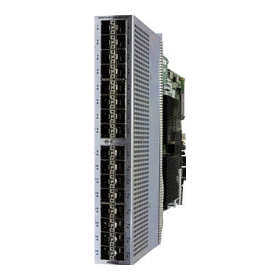
Page 10: Figure 1-1: 3067Vip10G-3G-Hw
3067VIP10G-3G Series Advanced Multi-Image Display Processors with 10G Interface Figure 1-1: 3067VIP10G-3G-HW Page - 2 Revision 1.0... -
Page 11: Technical Specifications
3067VIP10G-3G Series Advanced Multi-Image Display Processors with 10G Interface TECHNICAL SPECIFICATIONS 2.1. INPUT • Format: Uncompressed 3G/HD/SD over 10GE 2.2. OUTPUT • Format: Uncompressed 3G/HD/ over 10GE (Optional: JPEG2000 over 10GE) • Resolution supported: 1080p/59.94,1080p/60 1080p/50, 720p/59.94,720p/60 and 720p/50 2.3. CONNECTIVITY •... -
Page 12: Input & Output Options
3067VIP10G-3G Series Advanced Multi-Image Display Processors with 10G Interface 2.7. INPUT & OUTPUT OPTIONS • Quad uncompressed mosaic output, 36 uncompressed 3G/HD/SD input over 10GE. +36x4 Maximum of 36 images across 4 display. • Single uncompressed mosaic output, 32 uncompressed 3G/HD/SD input over 10GE. +32x1 •... -
Page 13: Getting Started
3067VIP10G-3G Series Advanced Multi-Image Display Processors with 10G Interface GETTING STARTED 3.1. REAR PLATE DESCRIPTION For future implementation For future implementation SFP+: 10Gbps Data Ports Page - 5 Revision 1.0... -
Page 14: Hardware Installation
The 3067VIP10G module requires a first time initialization to set up proper network parameters. Procedure 1. Connect the Evertz serial upgrade cable (ribbon cable) to the 2x3 header at the front edge of the 3067VIP10G card. 2. Start a terminal program and configure the port settings. -
Page 15: Figure 3-2: Serial Port - Login Prompt
3067VIP10G-3G Series Advanced Multi-Image Display Processors with 10G Interface 3. Boot up module, a login prompt will appear, enter: Figure 3-2: Serial Port – Login Prompt • “customer” for user name <Enter> • “customer” for password <Enter> 4. Once logged in, we will be configuring the network settings. Figure 3-3: Serial Port –... -
Page 16: Figure 3-4: Serial Port - Network Setup Menu
3067VIP10G-3G Series Advanced Multi-Image Display Processors with 10G Interface Figure 3-4: Serial Port – Network Setup Menu • Set all network configurations for each control network. • Select <X> to Exit. 6. Once all network settings are completed and exited back to main menu •... -
Page 17: Web Interface
3067VIP10G-3G Series Advanced Multi-Image Display Processors with 10G Interface WEB INTERFACE Different product licenses will enable different product features. Depending on the product features enabled, there will be different tabs and controls that will need to be configured. For the purpose of this manual, we have enabled all product features. -
Page 18: System Tab
3067VIP10G-3G Series Advanced Multi-Image Display Processors with 10G Interface 4.1. SYSTEM TAB Figure 4-2: WebEASY - System Tab - Part 1 ® Control Port Control (must reboot in order for new settings to take effect) There are two control ports for configurations. IP Address: This control allows the user to set the IP address on the Control Port. - Page 19 3067VIP10G-3G Series Advanced Multi-Image Display Processors with 10G Interface Figure 4-3: WebEASY - System Tab Part 2 ® Data Port Monitor For the monitoring on the 12 Data Ports on main and backup. Received Optical Power: This parameter indicates the received optical power status on the SFP-Rx and is measured in 1dBm units.
- Page 20 3067VIP10G-3G Series Advanced Multi-Image Display Processors with 10G Interface Received Data Ethernet Total Bitrate (Gbps): This parameter indicates the bit rate received on Ethernet ports in Gbps. Transmitted Data Ethernet Total Bitrate (Gbps): This parameter indicates the bit rate transmitted on the Ethernet Port in Gbps.
-
Page 21: Figure 4-3: Webeasy
3067VIP10G-3G Series Advanced Multi-Image Display Processors with 10G Interface Figure 4-4: WebEASY - System Tab - Part 2 ® Page - 13 Revision 1.0... - Page 22 3067VIP10G-3G Series Advanced Multi-Image Display Processors with 10G Interface Temperature Top Area Temperature: This parameter allows the user to verify the top of the FPGA module temperature. This value is represented in degrees Celsius. Bottom Area Temperature: This parameter allows the user to verify the bottom of the FPGA module temperature.
-
Page 23: Input Control Tab
3067VIP10G-3G Series Advanced Multi-Image Display Processors with 10G Interface Factory Reset: This click button control is used to reset all configurations back to factory settings. System Default Gateway: This control is used to select the default gateway. Options are Ethernet 1 or Ethernet 2. - Page 24 3067VIP10G-3G Series Advanced Multi-Image Display Processors with 10G Interface Input Control Input selection for the 36 input streams Input Port Enable: This control is used to enable or disable the input streams. Input Port Select: This control is used to select which port, Main or Backup, will be used on the output stream.
-
Page 25: Figure 4-4: Webeasy
3067VIP10G-3G Series Advanced Multi-Image Display Processors with 10G Interface Figure 4-6: WebEASY - Input Control Tab - Part 2 ® IP Input IGMP Control On the 36 streams for Main and Back up, the user can assign IGMP V3 settings for the streams. The user can Include or Exclude six source IP addresses. -
Page 26: Figure 4-5: Webeasy
3067VIP10G-3G Series Advanced Multi-Image Display Processors with 10G Interface Figure 4-7: WebEASY - Input Control Tab - Part 3 ® This section has been reserved for future implementation. Page - 18 Revision 1.0... -
Page 27: Input Properties Control Tab
3067VIP10G-3G Series Advanced Multi-Image Display Processors with 10G Interface 4.3. INPUT PROPERTIES CONTROL TAB Figure 4-8: WebEASY - Input Properties Control Tab ® Global Control Default Settings and Copy Input 1 Settings to Others are reserved for future implementation Input Settings Control For the 36 input streams Desired Video Type: This control is used to select the expected video type on input stream. - Page 28 3067VIP10G-3G Series Advanced Multi-Image Display Processors with 10G Interface • Trigger Available Expected • Trigger Time Type • Trigger Splice Inc Type VANC Source ID Number and VANC Source ID Label Selection are reserved for future implementation. Input Video Properties This section is reserved for future implementation.
-
Page 29: Input Monitor Tab
3067VIP10G-3G Series Advanced Multi-Image Display Processors with 10G Interface 4.4. INPUT MONITOR TAB Figure 4-9: WebEASY - Input Monitor - Part 1 ® Input Monitor Received on SFP Port: For future implementation. RTP Sequence Error Count: This monitor is used to display the number of RTP sequence error counts.. - Page 30 3067VIP10G-3G Series Advanced Multi-Image Display Processors with 10G Interface Received Ethernet Bandwidth (Gbps): This monitor is used to display the amount of bandwidth received by the input stream. Video Refresh Rate (Hz): This monitor is used to display the detected refresh rate on the input stream.
-
Page 31: Figure 4-6: Webeasy
3067VIP10G-3G Series Advanced Multi-Image Display Processors with 10G Interface Figure 4-10: WebEASY - Input Properties Control Tab – Part 2 ® This section is reserved for future implementation. Page - 23 Revision 1.0... -
Page 32: Output Control Tab
3067VIP10G-3G Series Advanced Multi-Image Display Processors with 10G Interface 4.5. OUTPUT CONTROL TAB Figure 4-11: WebEASY - Output Control Tab ® Output Control Output Resolution: This control allows the user to select the output resolution. Options are 1080p or 720p. Layout: Selects different screen layouts for the output display. - Page 33 3067VIP10G-3G Series Advanced Multi-Image Display Processors with 10G Interface Audio Input Select (1 to 36): Reserved for future implementation. Standard Selection: This control is used to select the output standard used for transporting the video over IP. Options include: • Evertz_TS •...
-
Page 34: Umd Control Tab
3067VIP10G-3G Series Advanced Multi-Image Display Processors with 10G Interface 4.6. UMD CONTROL TAB Figure 4-12: WebEASY - UMD Proxy Control Tab ® UMD Control For Readers 1 and 2 Protocol: This control is used to select the UMD protocol to use. Options include: •... -
Page 35: Encoder Control Tab
3067VIP10G-3G Series Advanced Multi-Image Display Processors with 10G Interface 4.7. ENCODER CONTROL TAB Figure 4-13: WebEASY - Encoder Control Tab ® Encoder Control For Encoder 1 and 2 Encoder Enable: This control is used to enable or disable the encoder. TS Packets Per Frame: This control is used to select the number of the transmission packets used when forming the IP datagram. -
Page 36: System Notify
3067VIP10G-3G Series Advanced Multi-Image Display Processors with 10G Interface Video Bit Rate: This monitor is used to display the video bit rate on the transport stream. Advanced Control For Encoder 1 and Encoder 2 Latency Mode: This control is used to select the latency mode for the encoders. Options are: •... -
Page 37: Video Notify Tab
3067VIP10G-3G Series Advanced Multi-Image Display Processors with 10G Interface Received Link Error: This control is used to send a trap, when set to True, if there is a receiving link error. System Fault Present indicates the state of error condition. Green indicates no fault while red indicates a fault. - Page 38 3067VIP10G-3G Series Advanced Multi-Image Display Processors with 10G Interface Black Reset Duration (0 to 60 seconds): This control sets the amount of time after the non-black video becomes present for the fault to go away. Freeze Duration (6 to 9000 frames): This control sets the number of frames for a freeze motion fault to appear.
-
Page 39: 4.10. Audio Notify Tab
3067VIP10G-3G Series Advanced Multi-Image Display Processors with 10G Interface 4.10. AUDIO NOTIFY TAB Figure 4-16: WebEASY - Audio Notify Tab – Part 1 ® Global Control Default Settings and Copy Input 1 Settings to Others are reserved for future implementation. Page - 31 Revision 1.0... - Page 40 3067VIP10G-3G Series Advanced Multi-Image Display Processors with 10G Interface Audio Monitoring Control For the 36 input streams and 16 channels of audio per input stream Audio Over Level (-30 to 0 dBFS): The control sets the threshold limit for the audio Over level (relative loudness).
-
Page 41: Figure 4-17: Webeasy
3067VIP10G-3G Series Advanced Multi-Image Display Processors with 10G Interface Figure 4-17: WebEASY - Audio Notify Tab – Part 2 ® Audio Monitoring Control For the 36 input streams and 8 groups of audio per input stream Mono Detection Level (20 to 50): This control is used to detect the mono phase on the audio pair. A value of 20 is a strict condition and difficult to detect. -
Page 42: Audio Notify Tab - Part 2
3067VIP10G-3G Series Advanced Multi-Image Display Processors with 10G Interface Figure 4-18: WebEASY - Audio Notify Tab – Part 3 ® Note: Screen capture, in Figure 4-18, is only a portion of the Audio Notify section. Audio Notify allows for fault monitoring and traps to be send on audio faults, previously configured in the sections above on the 36 input streams. -
Page 43: 4.11. Advanced Notify Control
3067VIP10G-3G Series Advanced Multi-Image Display Processors with 10G Interface 4.11. ADVANCED NOTIFY CONTROL Figure 4-19: WebEASY - Advanced Notify Control Tab – Part 1 ® Global Control Default Settings and Copy Input 1 Settings to Others are reserved for future implementation Picture Level Control For the 36 input streams Active Picture Level Max Level (60 to 108) %IRE: This control sets the upper threshold for... - Page 44 3067VIP10G-3G Series Advanced Multi-Image Display Processors with 10G Interface Active Picture Level Min Reset Duration (0 to 60) seconds: This control sets the amount of time for the APL level to be above the lower threshold limit for the fault to go away. Percent Picture Level Max Percent (0 to 100) %: Defines the percentage of the total picture used to calculate the max luminance based on the IRE threshold.
-
Page 45: Figure 4-10: Webeasy
3067VIP10G-3G Series Advanced Multi-Image Display Processors with 10G Interface Figure 4-20: WebEASY - Advanced Notify Control Tab – Part 2 ® CC Control For the 36 input streams on CC1 to CC 4 CC Loss Duration (0 to 3600) seconds: This control is used to set the amount of time for the loss of the CC before triggering a fault condition. -
Page 46: Advanced Control Notify Tab - Part 3
3067VIP10G-3G Series Advanced Multi-Image Display Processors with 10G Interface Figure 4-21: WebEASY - Advanced Control Notify Tab - Part 3 ® Nielsen Control For the 36 input streams NAES Source Loss Reset Duration: This control is used to set the amount of time after the return of the NAES Source Loss for the fault to go away. - Page 47 3067VIP10G-3G Series Advanced Multi-Image Display Processors with 10G Interface AMOL Source Loss Duration: This control is used to set the amount of time for the loss of the AMOL Source before triggering a fault condition. AMOL Source Loss Reset Duration: This control is used to set the amount of time after the return of the AMOL source for the fault to go away.
-
Page 48: Figure 4-12: Webeasy
3067VIP10G-3G Series Advanced Multi-Image Display Processors with 10G Interface Figure 4-22: WebEASY - Advanced Control Notify Tab – Part 4 ® EIA 708 Control For the 36 input streams and EIA Service 1 to EIA Service 16 EIA 708 Error Duration (0 to 3600 seconds): This control is used to set the amount of time for the loss of the Services before triggering a fault condition. -
Page 49: Figure 4-15: Webeasy
3067VIP10G-3G Series Advanced Multi-Image Display Processors with 10G Interface Figure 4-23: WebEASY - Advanced Control Notify Tab – Part 5 ® ANC Control For the 36 input streams Teletext Duration (0 to 3600 seconds): This control is used to set the amount of time for the loss of the Teletext before triggering a fault condition. - Page 50 3067VIP10G-3G Series Advanced Multi-Image Display Processors with 10G Interface SMPTE AFD Loss Reset Duration (0 to 60 seconds): This control is used to set the amount of time after the return of the SMPTE AFD for the fault to go away. SMPTE AFD Change Reset Duration (0 to 60 seconds): This control is used to set the amount of time after a change in the SMPTE AFD for the fault to go away.
-
Page 51: Advanced Control Notify Tab - Part 4
3067VIP10G-3G Series Advanced Multi-Image Display Processors with 10G Interface WSS Loss Reset Duration (0 to 60 seconds): This control is used to set the amount of time after the return of the WSS for the fault to go away. XDS Loss Duration (0 to 3600 seconds): This control is used to set the amount of time for the loss of the XDS before triggering a fault condition. - Page 52 3067VIP10G-3G Series Advanced Multi-Image Display Processors with 10G Interface Video Control For the 36 input streams Video Standard Change Duration (0 to 900) frames: This control is used to set the number of frames for the change in video standard before triggering a fault condition. Video Standard Change Reset Duration (0 to 60) seconds: This control is used to set the amount of time for the video standard changed for the fault to go away.
-
Page 53: Advanced Notify
3067VIP10G-3G Series Advanced Multi-Image Display Processors with 10G Interface 4.12. ADVANCED NOTIFY Figure 4-25: WebEASY - Advanced Notify Tab – Part 1 ® Global Control Default Settings and Copy Input 1 Settings to Others are reserved for future implementation Advanced Notify Advanced Notify allows for fault monitoring and traps to be send on video faults, previously configured in the Advanced Notify Control tab, on the 36 input streams. -
Page 54: 4.13. Advanced Audio Notify
3067VIP10G-3G Series Advanced Multi-Image Display Processors with 10G Interface 4.13. ADVANCED AUDIO NOTIFY Figure 4-26: WebEASY - Advanced Audio Notify Tab – Part 1 ® Global Control Default Settings and Copy Input 1 Settings to Others are reserved for future implementation Advanced Audio Notify Control For the 36 input streams and 8 audio groups Non PCM Missing Duration (0 to 99 seconds): This control is used to set the amount of time for the... -
Page 55: Figure 4-27: Webeasy
3067VIP10G-3G Series Advanced Multi-Image Display Processors with 10G Interface Figure 4-27: WebEASY - Advanced Audio Notify Tab – Part 2 ® Advanced Audio Notify Advanced audio Notify allows for fault monitoring and traps to be send on audio faults, previously configured in sections above, on the 36 input streams. - Page 56 3067VIP10G-3G Series Advanced Multi-Image Display Processors with 10G Interface Figure 4-28: WebEASY - Advanced Audio Notify Tab – Part 3 ® Audio Loudness Monitoring Control For the 36 input streams Audio Loud Integration Time (1 to10): Defines the Audio Loudness integration time for the status in seconds.
- Page 57 3067VIP10G-3G Series Advanced Multi-Image Display Processors with 10G Interface Audio Loud Over Duration (0 to 600) sec: This control is used to set the amount of time for Audio Loud Over before triggering a fault condition. Audio Loud Over Reset Duration (0 to 120) seconds: This control is used to set the amount of time after the Audio Loud Over is below threshold for the fault to go away.
- Page 58 3067VIP10G-3G Series Advanced Multi-Image Display Processors with 10G Interface Figure 4-29: WebEASY - Advanced Audio Notify Tab – Part 4 ® Audio Loudness Notify Audio Loudness Notify allows for fault monitoring and traps to be send on audio faults, previously configured in sections above, on the 36 input streams.
-
Page 59: Firmware Upgrade
Selecting the Upgrade tab, will take you to where the current firmware version is shown. Should the firmware version be outdated, you will need to download the firmware image file. NOTE: Contact Evertz get the latest firmware file. Page - 51 Revision 1.0... -
Page 60: Figure 4-28: Webeasy
3067VIP10G-3G Series Advanced Multi-Image Display Processors with 10G Interface Figure 5-2: WebEASY - Firmware Upgrade Menu ® Click Choose File and browse to locate image file. Once selected, click Open (Step 1) to advance to next step. Click Upgrade (Step 2) and watch progress bar for status. Once completed, the device will automatically restart.
Need help?
Do you have a question about the 3067VIP10G-3G-HW and is the answer not in the manual?
Questions and answers