Table of Contents
Advertisement
Quick Links
Advertisement
Table of Contents

Related Manuals for KPS DCM8500PV


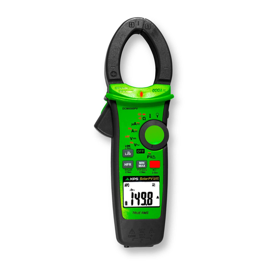
Summary of Contents for KPS DCM8500PV
-
Page 2: Safety Information
! Safety Information Understand and follow operating instructions carefully. Use the meter only as. WARNING If the equipment is used in a manner not specified by the manufacturer, the protection provided by the equipment may be impaired. Always use proper terminals, switch position, and range for measurements. To reduce the risk of fire or electric shock, do not use this product around explosive gas or in damp locations. -
Page 3: Maintenance
Unsafe Voltage To alert you to the presence of a potentially hazardous voltage, when the Tester detects a voltage ≧30 V or a voltage overload (OL) in V, mV, LoZ. The symbol is displayed. Maintenance Do not attempt to repair this Meter. It contains no user serviceableparts. Repair or servicing should only be performed by qualified personnel. -
Page 4: Making Basic Measurements
Making Basic Measurements ! CAUTION When connecting the test leads to the DUT (Device Under Test) connect the common test leads before connecting the live test leads ; when removing the test leads, remove the live test leads before removing the common test leads. Measuring Voltage Dial the switch to select the measuring function. -
Page 5: Measuring Current
Measuring Current CAT.IV 600V CAT.III 1000V with respect to earth for the jaw. Tactile Barrier for hand guard. Do not hold the meter across the Barrier I+(-I)=0 Dial the switch and press the Function button to select the measuring function. Note : Torch will be on when jaw is opened. -
Page 6: Measuring Temperature °C / °F
Measuring Temperature °C / °F ° C Funtion Button ° F Dial the switch and press the Function button to select °C / °F mode. Measuring μA Flame sensor Control Module Dial the switch and press the Function button to select AC/DC mode. -
Page 7: Using The Function
Measuring Current with Flex Clamp Meter Keep the range of Flex Clamp meter at 3000A/3V output ratio. Using the Function Switch Function Position Press the Function button to change the function on the same switch position. ° Measuring Frequency Funtion Button... - Page 8 Backlight Press > 2 sec 2 Sec Press Function button for over 2 sec. to turn Backlight on / off. MIN/MAX MAX MIN Press Press Press Press Button > 2 sec to exit the MINMAX mode Press The MAX/MIN mode records the min and max input values. When the input goes below the recorded min value or above the recorded max value, the meter records the new value.
-
Page 9: Smart Hold
Smart Hold HOLD HOLD HOLD ZERO The meter will beep continuously and the display will flash if the measured signal is larger than the display reading by 50 counts. (However, it can not detect across the AC and DC Voltage / Current). DCA ZERO Remove the jaw from the conductor before performing DCA ZERO. -
Page 10: Auto Power Off
INRUSH In inrush current mode, select the suitable measurement range by pressing HFR/INRUSH button before triggering the inrush current measurement. Watting Tigger Press > 2 sec Inrush 2 Sec Press > 2 sec After Tigger Inrush 2 Sec Auto Power Off After Specified Time Without Operation Wake up the meter by dialing the switch or pressing any button. - Page 11 Time Setting of Auto Power Off Funtion Button Funtion Button Press the function button and turn the meter on. Then press the function button to select the time. The time can be 5 minutes, 10 minutes, 20 minutes, and disabled (OFF).
-
Page 12: Data Logger
Data Logger The meter can store up to 4000 data in memory. Press button for more than 2 seconds to activate Data logger mode. The meter will enter Time interval setting mode. Press button again to select time interval. The interval can be 1 second, 5 seconds, 10 seconds, 30 seconds, 60 seconds. - Page 13 The open-air communication range is up to 10m. Download “KPS Link” App via the following QR Code. Turn on Bluetooth function of the meter and open “KPS Link” to connect the DMM. The Bluetooth icon of the meter will freeze on LCD after the connection establishes successfully.
-
Page 14: Specifications
Low Battery and Battery Replacement ! Warning Remove test leads from Meter before opening the battery cover or Meter case. Specifications General Specifications Display : 6000 counts. Overrange Indication : ”OL” or “-OL” Measure : Samples 3 times per second . Max Conductor Size of JAW : 37mm diameter Dimensions (W x H x D) : 62mm x 240mm x 41mm Weight : approx. -
Page 15: Electrical Specifications
Electrical Specifications Accuracy is given as ± (% of reading + counts of least significant digit) at 23°C ± 5°C, with relative humidity Less than 80% R.H., and is specified for 1 year after calibration. (1) Temperature coefficient 0.2 x (Specified accuracy) / °C, < 18°C, > 28°C (2) AC Function ACV and ACA specifications are ac coupled, true R.M.S. - Page 16 (7) PV AC Voltage Range OL Reading Resolution Accuracy 600.0V 660.0V 0.1V ±(2.0% + 5D) 1500V 1600V Frequency Response : 45 ~ 400Hz (Sine Wave) Input Impedance : 10MΩ // less than 100pF Overload Protection : AC/DC 1000V (8) AC/DC μA Range OL Reading Resolution...
- Page 17 (12) Frequency Range OL Reading Resolution Accuracy 100.00Hz 100.00Hz 0.01Hz 1000.0Hz 1000.0Hz 0.1Hz ±(0.3% + 3D) 10.000kHz 10.000kHz 0.001kHz Minimum Sensitivity : > 5V (for ACV 1Hz ~ 10kHz) > 8A (for ACA 1Hz ~ 1kHz) Minimum Frequency : 1Hz Overload Protection : AC/DC 1000V and 600A (13) HFR (High Frequency Rejection) Available for ACV, ACA and, Flexible Current Probe.
- Page 18 (18) Capacitance Range OL Reading Resolution Accuracy 100.0μF 110.0μF 0.1μF ±(1.9% + 2D) 1000μF 1100μF 1μF Overload Protection : AC/DC 1000V (19) VoltSeek Voltage Range of High Sensitivity : 80V ~ 1000V (At the top edge of the jaw) Voltage Range of Low Sensitivity : 160V ~ 1000V (At the top edge of the jaw) (20) Temperature Range OL Reading...
- Page 19 ATL-PV Test Leads Instruction Probe tip guard cap Finger Guard For CAT III or CAT IV environments, use the test leads with the probe tip guard cap fixed firmly. Without the probe tip guard cap, the test leads can be used in CAT II environment ONLY.
- Page 20 ! CAUTION When using test leads or probes, keep your fingers behind the finger guards. Use caution with voltages above 30 Vac rms, 42 Vac peak, or 60 Vdc. These voltages pose a shock hazard. If the test lead is used in a manner not specified by the manufacturer, the protection provided by the equipment may be impaired.
Need help?
Do you have a question about the DCM8500PV and is the answer not in the manual?
Questions and answers