Table of Contents
Advertisement
Quick Links
R8C/34K Group
USB Host Evaluation Board R0K5R8C34DK2HBR
Hardware Instruction Manual
Introduction
This application note is an instruction manual for the hardware used with evaluation board R0K5R8C34DK2HBR,
which operates the USB Host function and microcontroller peripheral functions for R8C/34K Group MCUs.
Target Device
R8C/34K Group
Contents
1.
Preface .............................................................................................................................................. 2
2.
Important ........................................................................................................................................... 3
3.
Precautions for Safety....................................................................................................................... 5
4.
Function Overview............................................................................................................................. 8
5.
Evaluation Board Configuration ........................................................................................................ 9
6.
Evaluation Board Setup .................................................................................................................. 11
7.
Function Descriptions...................................................................................................................... 16
8.
MCU Pin Setting Examples............................................................................................................. 20
9.
Circuit Diagram................................................................................................................................ 22
10. Parts Layout Diagram ..................................................................................................................... 22
11. Parts List ......................................................................................................................................... 22
R01AN0649EJ0110 Rev.1.10
Jul 21, 2011
APPLICATION NOTE
R01AN0649EJ0110
Rev.1.10
Jul 21, 2011
Page 1 of 26
Advertisement
Table of Contents

Subscribe to Our Youtube Channel
Related Manuals for Renesas R0K5R8C34DK2HBR


Summary of Contents for Renesas R0K5R8C34DK2HBR
-
Page 1: Table Of Contents
Jul 21, 2011 Hardware Instruction Manual Introduction This application note is an instruction manual for the hardware used with evaluation board R0K5R8C34DK2HBR, which operates the USB Host function and microcontroller peripheral functions for R8C/34K Group MCUs. Target Device R8C/34K Group Contents Preface .............................. -
Page 2: Preface
Hardware Instruction Manual Preface The R0K5R8C34DK2HBR is the evaluation board of the USB Host function and built-in functions in R8C/34K Group MCUs. This instruction manual explains how to setup up and operate the related hardware and offers cautionary notes concerning usage. -
Page 3: Important
"Product" herein encompasses neither the customer's user system nor the host machine. Purpose of use of the product: This product is a device to support the development of systems that uses the R8C/34K Groups of Renesas MCUs. It provides support for system development in both software and hardware. - Page 4 Renesas or to a third party. (3) This user’s manual and this product are copyrighted, with all rights reserved by Renesas. This user’s manual may not be copied, duplicated or reproduced, in whole or part, without prior written consent from Renesas.
-
Page 5: Precautions For Safety
R8C/34K Group USB Host Evaluation Board R0K5R8C34DK2HBR Hardware Instruction Manual Precautions for Safety Definitions of Signal Words This chapter describes the precautions which should be taken in order to use this product safely and properly. Be sure to read and understand this chapter before using this product. - Page 6 R8C/34K Group USB Host Evaluation Board R0K5R8C34DK2HBR Hardware Instruction Manual Warning WARNING Warnings for Power Supply: If you connect the attached power cable with the stabilized power supply, be sure to connect it with the appropriate polarity (the red cable is connected to the power line. The black cable is connected to the ground).
- Page 7 (including all accessories) is not intended for household use. After use the equipment cannot be disposed of as household waste, and the WEEE must be treated, recycled and disposed of in an environmentally sound manner. Renesas Electronics Europe GmbH can take back end of life equipment, register for this service at “http://www.renesas.eu/weee”. ...
-
Page 8: Function Overview
R8C/34K Group USB Host Evaluation Board R0K5R8C34DK2HBR Hardware Instruction Manual Function Overview Supported Functions The evaluation board supports the following functions using the R8C/34K Group MCU functions with on-board circuits. • USB2.0 Function module (full-speed host function) • On-chip debug function with connection to E8a emulator •... -
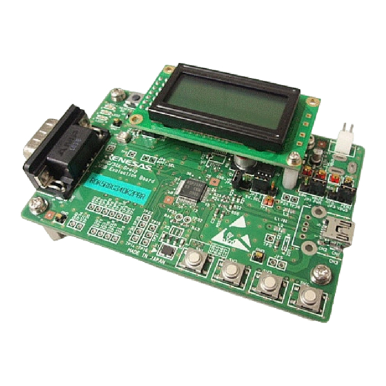
Page 9: Evaluation Board Configuration
(Standard A) R8C/34K Connector User SW (4) MCU extracted function test pins Figure 1 R0K5R8C34DK2HBR Board (Top View) Evaluation Board Specifications Table 1 Table 2 lists the function specifications of the evaluation board and provides the operating environment, power specifications and dimensions. - Page 10 R8C/34K Group USB Host Evaluation Board R0K5R8C34DK2HBR Hardware Instruction Manual Table 2 R0K5R8C34DK2HBR Voltage, Dimensions, Environment Specifications Parameter Specifications Operating Environment Temperature: 5~35°C Conditions Humidity: no condensation Surrounding gas: no corrosive gas Operating Voltage and Supply Supply Voltage: 5.0V(4.7V to 5.5V) / 3.3V(3.0V to 3.6V) Source Note: When operating the USB Host function at 3.0V to 3.6V or E8a supply source,...
-
Page 11: Evaluation Board Setup
R8C/34K Group USB Host Evaluation Board R0K5R8C34DK2HBR Hardware Instruction Manual Evaluation Board Setup Packing Components Confirm all components included with the evaluation board before assembling. Figure2 shows a photo of all Assembly components; Table 3 lists the name and quantity of each component. Use four screws to add spacers to each corner of the board, allowing space for parts mounted on the backside of the board. - Page 12 R8C/34K Group USB Host Evaluation Board R0K5R8C34DK2HBR Hardware Instruction Manual Figure 3 JP1 ( ) selects the main power supply source for components that can run on either 3.3V or 5V, such as the MCU, user LED, user switch, and RS232C transceiver. The supply source can be selected from the following: (1) stabilized power supply (DC), (2) E8a supply source (E8a).
- Page 13 R8C/34K Group USB Host Evaluation Board R0K5R8C34DK2HBR Hardware Instruction Manual Figure 3 JP1 Main power supply switch “DC” setting “E8a” setting Figure 4 Stabilized power supply connector (CN7) ←External input pin (TP1) “External input (Ext)” setting Figure 5 JP2 5V-dedicated power supply switch “Internal input (int)” setting Figure 6 JP3 VBUS switch “Host”...
- Page 14 The on-chip debugger function of the R8C/34K Group MCU can be used by connecting the board to the E8a emulator manufactured by Renesas Electronics Corp. As shown in Figure 8, a 14-pin connector (CN6) is located on the back of the board for connecting the E8a emulator.
- Page 15 R8C/34K Group USB Host Evaluation Board R0K5R8C34DK2HBR Hardware Instruction Manual Connecting the Serial Writer The built-in Flash memory (user ROM area) in R8C/34K Group MCUs can be re-programmed with a computer or MCU (serial writer) that has a clock-asynchronous serial transmission (UART 0ch).
-
Page 16: Function Descriptions
R8C/34K Group USB Host Evaluation Board R0K5R8C34DK2HBR Hardware Instruction Manual Function Descriptions Figure 12 is a general outline of the functions on the evaluation board. The board is equipped with an R8C/34K Group Table 1 MCU and provides these functions using the MCU peripheral functions with the on-board circuits listed in Each function is described in detail below. - Page 17 R8C/34K Group USB Host Evaluation Board R0K5R8C34DK2HBR Hardware Instruction Manual User Switches with A/D Detection (Orange dot line area of Figure 12) The evaluation board is equipped with four user switches. The MCU A/D function detects voltage when each switch is pushed.
- Page 18 R8C/34K Group USB Host Evaluation Board R0K5R8C34DK2HBR Hardware Instruction Manual LCD Module Control (Orange dot line area of Figure 12) The evaluation board includes an LCD module that is controlled through MCU I/O ports. The LCD module displays 2 lines of 8 characters each; this is a character type module with the character font stored in the module. The LCD module Table 8 is controlled with 6 pins: a 4-bit data bus and 2 control signals.
- Page 19 R8C/34K Group USB Host Evaluation Board R0K5R8C34DK2HBR Hardware Instruction Manual Test Pins on the board In order to connect external devices and enable MCU functions, test pins from MCU ports are grouped on the lower left area of the evaluation board, as shown in Figure 14 and Figure 15 . Test Pin (TP) No. and corresponding port functions...
-
Page 20: Mcu Pin Setting Examples
R8C/34K Group USB Host Evaluation Board R0K5R8C34DK2HBR Hardware Instruction Manual MCU Pin Setting Examples Table 10 shows examples of settings for each MCU pin. Refer to instructions in the corresponding MCU user’s manual: hardware on how to treat unused pins for functions not used on the evaluation board. - Page 21 R8C/34K Group USB Host Evaluation Board R0K5R8C34DK2HBR Hardware Instruction Manual Table 10 Example Settings for Used and Unused MCU Pin Functions Pin No. Pin Function Function Example setting when not using function P60 (TP15) P60 Input (built-in pull-up resistor valid)
-
Page 22: Circuit Diagram
R8C/34K Group USB Host Evaluation Board R0K5R8C34DK2HBR Hardware Instruction Manual .*1 : When select “Input direction” with invalid of internal pull-up resistor, the input pin is in the high-impedance state. *2 : When select “Output direction”, output signal might conflict. - Page 23 R8C/34K Group USB Host Evaluation Board R0K5R8C34DK2HBR Hardware Instruction Manual Website and Support Renesas Electronics Website http://www.renesas.com/ USB Device Page http://www.renesas.com/prod/usb/ Inquiries http://www.renesas.com/inquiry All trademarks and registered trademarks are the property of their respective owners. R01AN0649EJ0110 Rev.1.10 Page 23 of 26...
- Page 24 Appendix 1 Circuit Diagram V C C _ D C TP30 TP30 HK-5-G(RED) HK-5-G(RED) VCC_MAIN VCC_DC VCC_Main + C30 + C30 WL-1(4P) WL-1(4P) KLDX-0202-A KLDX-0202-A 0.1u 0.1u C C _ E 8 a TP29 TP29 VCC_E8a HK-5-G(RED) HK-5-G(RED) VCC_VBUS VCC_E8a TP31 TP31 BS2P-SHF-1AA(LF)(SN)
- Page 25 Appendix2: Parts Layout Diagram 1. Front Surface...
- Page 26 2. Rear Surface...
- Page 27 SML-310VT ROHM LED2 SML-310YT ROHM Yellow LED3 SML-310MT ROHM Green Schottky barrier diode D1-6,D8 RB520S-30 ROHM D5,D6 are unmounted Schottky barrier diode MBRS130LT3G Onsemi Zener Diode RKZ6.8Z4KT Renesas Electronics unmount Zener Diode HZU6.8Z Renesas Electronics unmount PPL - R0K5R8C34DK2HBR (1/3)
- Page 28 0.1u C32 is unmoun Chip Monolithic Ceramic Capacitor GRM188B11E104KA01D Murata Manufacturing C23,C24,C25,C28,C29,C31,C32 1.0u Chip Monolithic Ceramic Capacitor C3,C4,C8,C9,C12,C15,C21 GRM188R61E105KA01D Murata Manufacturing Chip Monolithic Ceramic Capacitor C26,C27 GRM1885C1H8R0DZ01D Murata Manufacturing Chip Monolithic Ceramic Capacitor C5,C6 GRM188R71C224KA01D Murata Manufacturing 0.22u PPL - R0K5R8C34DK2HBR (2/3)
- Page 29 Jumper Socket for JP1,JP2,JP3,JP4 XJ8A-0241 OMRON Housing for Power Cable H2P-SHF-AA Contact for Power Cable SHF-001T-0.8BS SHINAGAWA Black Cable for Power Cable UL1007-AWG24-BLACK 500mm ELECTRIC WIRE SHINAGAWA Red Cable foe Power Cable UL1007-AWG24-RED 500mm ELECTRIC WIRE PPL - R0K5R8C34DK2HBR (3/3)
- Page 30 Revision Record Description Rev. Date Page Summary 1.00 Jun 10.11 First edition issued 1.10 Jul 21.11 Correcting the wrong words...
- Page 31 General Precautions in the Handling of MPU/MCU Products The following usage notes are applicable to all MPU/MCU products from Renesas. For detailed usage notes on the products covered by this manual, refer to the relevant sections of the manual. If the descriptions under General Precautions in the Handling of MPU/MCU Products and in the body of the manual differ from each other, the description in the body of the manual takes precedence.
- Page 32 Electronics product for any application categorized as "Specific" without the prior written consent of Renesas Electronics. Further, you may not use any Renesas Electronics product for any application for which it is not intended without the prior written consent of Renesas Electronics. Renesas Electronics shall not be in any way liable for any damages or losses incurred by you or third parties arising from the use of any Renesas Electronics product for an application categorized as "Specific"...
Need help?
Do you have a question about the R0K5R8C34DK2HBR and is the answer not in the manual?
Questions and answers