
Related Manuals for Etrel INCH DUO


Summary of Contents for Etrel INCH DUO
- Page 1 ELECTRIC VEHICLE CHARGING STATION ETREL INCH DUO ELECTRICAL INSTALLATION SPECIFICS Document version: 1.4 Document date: 11. 11. 2021...
-
Page 2: Table Of Contents
Etrel INCH DUO | Electrical Installation Specifics Technical TABLE OF CONTENTS BASIC DESCRIPTION ..............1 About this Document ................. 1 Site Preparation ................. 1 Permits ....................2 Location....................3 Required Space ................4 Charging Station Dimensions ............4 Content, Optional and Extra Equipment..........5 Tools .................... -
Page 3: Basic Description
• Etrel_INCH_DUO_QuickStartGuide_Figures.pdf The document in front of you contains information on the specifics of electrical installation of the INCH DUO charging station. As it is necessary to consider the physical installation, basic information about it is also included. More information about physical installation is available in the document “Physical Installation”:... -
Page 4: Permits
Etrel INCH DUO | Electrical Installation Specifics Technical E XTE RN A L F A CT OR S Installation cannot be carried out in the event of extremely rainy or snowy weather or other external factors that can prevent safe mounting, installation, and commissioning of charging stations. -
Page 5: Location
It also provides best view and operation of the LCD screen. Etrel INCH charging station and its components (cable, casing, LCD screen...) are developed to be installed in the outside area meaning that charging station is resilient to the external actors (UV rays, rain, snow, cold etc.). -
Page 6: Required Space
Etrel INCH DUO | Electrical Installation Specifics Technical REQUIRED SPACE Basic installation of the charging station without arches requires an excavation of minimal dimensions of 550 mm x 420 mm (floor plan) and depth of 600 mm. If the charging station is installed together with two safety arches, dimensions of the required dimensions are approximately 800 mm x 550 mm. -
Page 7: Content, Optional And Extra Equipment
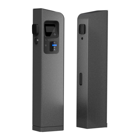
Etrel INCH DUO | Electrical Installation Specifics Technical | Two air vents are built into the station, one on the top of the back side and another in the middle of the back side. Air vents must not be blocked or obstructed by other items or objects. -
Page 8: Tools
Etrel INCH DUO | Electrical Installation Specifics Technical TOOLS To execute the installation of charging station multiple tools are needed: • Screwdriver, • Hex screwdriver (if charging station without key lock on maintenance doors), • Utility knife, • Self-adjusting crimping pliers for cables' end sleeves, •... -
Page 9: Product Description
Technical PRODUCT DESCRIPTION The Etrel’s public charging station INCH DUO is highly configurable and can be tailored to the client’s specific needs. It allows simultaneous charging of two vehicles with power of up to 2 x 22,08 kW and is equipped with standard Type 2 sockets (EN 61851 or EN 62196-2). -
Page 10: Components Overview
Etrel INCH DUO | Electrical Installation Specifics Technical COMPONENTS OVERVIEW The Etrel INCH DUO public charging station contains the following components: • Casing of the station, • two charging spots (Type 2 sockets, single- or three-phase), • main controller of the station, •... -
Page 11: Grid Connection
Etrel INCH DUO | Electrical Installation Specifics Technical GRID CONNECTION The charging station can be connected directly to the electricity distribution network or to an existing electrical installation nearby. Supply power depends on the charging power of each socket (according to the configuration of the charging station). - Page 12 Etrel INCH DUO | Electrical Installation Specifics Technical | identification of users (on the Control centre level), forward events that occur during its operation and execute billing for the services performed. The connection also enables communication from the Control centre towards the charging station, which enables remote access to the station for needs of maintenance or remote control.
-
Page 13: Circuit Diagram
Etrel INCH DUO | Electrical Installation Specifics Technical CIRCUIT DIAGRAM... -
Page 14: External Signal
Etrel INCH DUO | Electrical Installation Specifics Technical EXTERNAL SIGNAL DIGITAL INPUTS AND DIGITAL OUTPUTS Charger supports connecting four digital inputs and one digital output. Inputs and output are operating on 12 VDC, and maximal allowed load is 100 mA. Check pinout on the image below. -
Page 15: Cable Cross-Section Selection
The temperature conditions at the location and the length of the cable also have an impact. In general, the cable cross-section for the INCH DUO connection is around 10 - 25 mm , dependant on the installation method. Larger distances or clustering of several charging stations could require cables with larger cross-section. - Page 16 Etrel INCH DUO | Electrical Installation Specifics Technical Table 1: Minimum cable cross-section for continuous operating current of 64 A. A1 - Insulated single core conductors in conduit in a A1, A2: thermally insulated wall 16 mm A2 - Multicore cable in conduit in a thermally insulated wall...
- Page 17 Etrel INCH DUO | Electrical Installation Specifics Technical VO LT A GE DR OP The requirement for the maximum voltage drop of the installation can be different across different countries. Usually, it is required that the voltage drop of the installation is below 4 % (or in some cases below 5 %).
- Page 18 3,40 S HO RT CI RC UI T W IT H ST AN D Charging station INCH DUO has already installed miniature circuit breakers which protect against overload and short circuit. This protection can also be part of installation with different tripping characteristics.
-
Page 19: Other Consumption Or Production Of Electricity At The Location
Because the charging station needs information of other loads (or production) to be able to react appropriately, Etrel Load Guard device can be used. LO A D GU AR D... - Page 20 Etrel INCH DUO | Electrical Installation Specifics Technical | When there is local production of energy present at the location (e.g., photovoltaics), the available charging current can be higher, and the use of Load Guard make possible to always charge with maximum available current.
-
Page 21: Dimensioning Of A Cluster
320 A per phase, meaning that maximal charging power is 220,8 kW. Five INCH DUO charging stations can also be configured to be able to charge only with minimal charging current of 6 A per phase. These five INCH DUO charging stations will have maximal charging current of 60 A per phase, meaning that maximal charging power is 41,4 kW. -
Page 22: Cabling Route For The Connection Of Multiple Charging Stations
Etrel INCH DUO | Electrical Installation Specifics Technical CABLING ROUTE FOR THE CONNECTION OF MULTIPLE CHARGING STATIONS Charging station can be installed independently or combined in connection with other stations (the so-called clustering of charging stations). When multiple charging stations are installed in a single area, the power supply cables can be routed in several different ways. - Page 23 In case that Point-to-Point communication is needed for the power supply, all INCH Duo’s of the cluster with exclusion of the last one, should be equipped with double terminal clamps. Figure 8: Cluster cabling route - point to point network topology (daisy chain)
-
Page 24: Cluster Cables Cross-Section
CLUSTER CABLES CROSS-SECTION When INCH DUO is designated as cluster master, it is possible to connect 18 INCH DUO charging stations to this cluster, meaning that charging is supported to 36 electric vehicles simultaneously. If industrial computer is... - Page 25 | Considering maximal charging current of Mode 3 AC conductive charging point of 32 A (three-phase), the maximal charging power is 22,08 kW, meaning 44,16 kW for one INCH Duo. In large clusters this number rise significantly and can be in a range of large industrial consumers.
- Page 26 Etrel INCH DUO | Electrical Installation Specifics Technical | In the previous table the numbers of minimal charging current are presented. Such system allows charging of individual electric vehicles with maximal power of 22,08 kW. Power management can be used to set limitation of the maximal current of the complete cluster (determined by the location, e.g., main fuses).
- Page 27 Voltage drop in the power cable is proportional to the current of the load. When installing two INCH DUO charging stations, also voltage drops are twice as high as in case of one INCH DUO without considering any additional elements.
- Page 28 70 mm (Method G) or 150 mm (Method C) cables could be used when connecting 5 INCH DUO charging stations with maximum charging current available. Reviewing the selection of the cable with consideration of voltage drop, shows that allowable distance of conductors is a lot lower than if selecting higher cable cross-section.
- Page 29 Etrel INCH DUO | Electrical Installation Specifics Technical Table 15: Voltage drop in conductors with 120 mm cable cross-section and charging current of 320 A. Charging current Conductor Conductor 320 A (Five INCH DUO 120 mm 120 mm with max. current)
-
Page 30: Examples Of Connection
E XP AN DE D ST AR NE T W OR K The case presented in the following figure is possible with normal configuration of INCH DUO. The cable cross-sections must be determined in accordance with all three criteria. The distances are depending on the arrangement of parking spots and available space. - Page 31 Etrel INCH DUO | Electrical Installation Specifics Technical Figure 10: Example of INCH DUO connection – standard configuration Maximal continuous current of the cluster Maximal operating current of the presented case is 960 A. Cables supporting this current would need to be installed in E, F or G method of installation or a bus-bar system could be used.
- Page 32 Etrel INCH DUO | Electrical Installation Specifics Technical | • Method of installation D2: 240 mm • Method of installation E: 95 mm • Method of installation F: 95 mm • Method of installation G: 70 mm Cables from the 2nd level junction boxes to individual charging stations...
- Page 33 The cable cross-sections must be determined in accordance with all three criteria. Figure 11: Example of INCH DUO connection – use of double terminal clamps Maximal continuous current of the cluster Maximal operating current of the presented case is 960 A. Cables supporting this current would need to be installed in E, F or G method of installation or a busbar trunking system could be used.
- Page 34 INCH DUO units, except in the last one. If larger cables cross-section is needed, the double terminal clamps are too large to fit inside INCH DUO and the connection would be possible with use of additional junction boxes in front of every INCH DUO except the last.
- Page 35 E XP AN DE D PO IN T T O P O INT NE T W OR K Figure 12: Example of INCH DUO connection – use of double terminal clamps The figure presented above is showing possible selected configuration, after reviewing Case 1 and 2.
-
Page 36: Connecting Charging Station
Etrel INCH DUO | Electrical Installation Specifics Technical CONNECTING CHARGING STATION INSERTION OF CABLES THRO UGH THE INSTALLATION PIPE After the installation pipe is built into the concrete foundation, it is used for cabling and connection of the charging station. The concrete foundation must be left to dry for at least two days before the cables can be inserted in the installation pipe. -
Page 37: Preparation Of Cables
Etrel INCH DUO | Electrical Installation Specifics Technical PREPARATION OF CABLES Remove 20 mm of insulation from all cables and attach and compress the appropriate crimp tubes on all cables. To prevent cables from getting in the way of mounting the charging station, twist them into an installation pipe. - Page 38 Etrel INCH DUO | Electrical Installation Specifics Technical Figure 15: Overview of the power supply compartment The configuration of the charging station depends also on the type of grid connection. The charging station is usually connected to an existing installation.
- Page 39 Etrel INCH DUO | Electrical Installation Specifics Technical | To enable access to the power supply compartment first unscrew and remove the protective cover. There is a sticker on main connection element showing the correct designation of phases and neutral conductor. Remove the sticker and make sure that screws inside the main miniature circuit breaker (MCB) in which wires will be connected are unscrewed.
-
Page 40: Connection Of The Protective Earthing (Pe)
L3 of the system. The sequence of phases must be kept (L1, L2, L3). The software configuration must be properly made in charging station web interface and in the charging management platform (e.g., Etrel Ocean). Figure 19: Connecting the cables... -
Page 41: Connection Of The Power Cable
Etrel INCH DUO | Electrical Installation Specifics Technical CONNECTION OF THE POWER CABLE Prior to the beginning of work make sure that the main power supply is turned off. Required tools: Allen key (Hex key), wire stripper pliers (for stripping of insulation and for fine-core cables), crimping pliers. -
Page 42: Finishing Work
Etrel INCH DUO | Electrical Installation Specifics Technical Figure 20: Connecting the UTP cables FINISHING WORK Before closing the station, check the condition of the over-current protection elements and the residual current devices. Switches must be set to ON position. - Page 43 Etrel INCH DUO | Electrical Installation Specifics Technical Figure 21: Positions of MCBs and RCDs The hole in the bottom of the charging station should be filled with polyurethane foam filler (or similar material).
-
Page 44: Electrical Measurements
Etrel INCH DUO | Electrical Installation Specifics Technical ELECTRICAL MEASUREMENTS Electrical measurements must be performed by licensed electrician and must be in accordance with requirements set in national legislation. In this chapter only information on specifics of some of the electrical measurements is given. -
Page 45: Insulation Resistance Measurement
Etrel INCH DUO | Electrical Installation Specifics Technical INSULATION RESISTANCE MEASUREMENT Measurements of the insulation resistance of electric cables are performed between active conductors and between active conductors and the protective conductor connected to the earthing system. Insulation resistance, measured at a test voltage of 250 V d. c. is satisfactory if its value is not less than 1 MΩ. -
Page 46: Rcd Test
Etrel INCH DUO | Electrical Installation Specifics Technical RCD TEST The effectiveness of the automatic disconnection of the power supply by RCD devices should be checked with the use of appropriate test equipment, confirming that the relevant requirements are met and considering the operating characteristics of the device. -
Page 47: Effectiveness Of The Protection Against Electric Shock
Etrel INCH DUO | Electrical Installation Specifics Technical EFFECTIVENESS OF THE PROTECTION AGAINST ELECTRIC SHOCK In the case of TN systems, the effectiveness of protective measures in the event of damage by tripping the power supply is checked by: a) measurement of fault loop impedance, b) verification of the characteristics and/or effectiveness of the associated protection. -
Page 48: Earth Electrode Resistance Measurement
Etrel INCH DUO | Electrical Installation Specifics Technical EARTH ELECTRODE RESISTANCE MEASUREMENT Measuring of the resistance of an earth electrode shall be made by an appropriate method. Various methods exist and none of them is ideal, as they all have advantages and disadvantages. The methods, described below, are proposed in standard IEC 60364-6. - Page 49 Etrel INCH DUO | Electrical Installation Specifics Technical Electrodes arranged in linear formation Electrodes arranged in triangular formation Earth electrode test instrument according to IEC 61557-5 Earth electrode resistance Temporary probe electrode resistance (voltage) Temporary auxiliary probe earth electrode resistance (current) Figure 23.
- Page 50 Etrel INCH DUO | Electrical Installation Specifics Technical | The test should be performed on the live side of the main switch with the supply to the installation switched OFF and with the earthing conductor temporarily disconnected from the main earthing terminal (MET).
- Page 51 Etrel INCH DUO | Electrical Installation Specifics Technical | The voltage and current coils may be in individual clamps separately connected to an instrument or in a single combined clamp. This method is directly applicable to TN systems and within meshed earthing of TT systems.
-
Page 52: Operation And Charging Procedure
Etrel INCH DUO | Electrical Installation Specifics Technical OPERATION AND CHARGING PROCEDURE INCH DUO charging station can be controlled locally or remotely, through web interface, or through charging station management system. FIRST POWER UP Before starting the station, it is absolutely necessary to read this manual and the technical specification of the device. -
Page 53: First Charging Session
Etrel INCH DUO | Electrical Installation Specifics Technical SE T TI NG O F M AX IM AL C H ARG IN G C UR RE NT Max power is set by the installer based on the grid capabilities where charging station is installed. - Page 54 Etrel INCH DUO | Electrical Installation Specifics Technical | Plug and charge mode In the plug and charge mode message is shown to insert the cable and start the charging session. Needed authentication If authentication is needed, select the type of authentication that will be used to authorize and continue with the charging session.
- Page 55 Etrel INCH DUO | Electrical Installation Specifics Technical | Step 3: Connecting the cable After the successful authorization, the screen with the description to connect the cable is shown. Figure 28: Connect the cable to charging station and EV If the cable is connected before the authorization this screen will be left out and after the authorization next screen “Waiting for vehicle to...
- Page 56 Etrel INCH DUO | Electrical Installation Specifics Technical Figure 30: Example of shown energy on the LCD screen Figure 31: Display of charging time CHE C K ST A TU S O F T HE C H ARG IN G ST A TI ON In the web interface the information of the current session can be seen.
- Page 57 Etrel INCH DUO | Electrical Installation Specifics Technical Figure 32: Current session information displayed in the web interface LO C AL LY Ending the session can be performed with the same authorization method as for starting a session (using RFID cards, mobile application, PIN code)
- Page 58 P AY ING PR O CE D URE IN CA SE OF C LU S TE R OF C H AR GIN G ST A TI ON S It is possible to implement several INCH DUO charging stations into the same cluster and having the paying terminal installed only on one of them.
-
Page 59: Contact Information
Etrel INCH DUO | Electrical Installation Specifics Technical CONTACT INFORMATION TECHNICAL SUPPORT DEPARTMENT e-mail: support@etrel.com phone: +386 1 601 0127 CUSTOMER SUPPORT DEPARTMENT e-mail: sales@etrel.com phone: +386 1 601 0175 AUTHORISED SERVICE CENTRES e-mail: support@etrel.com phone: +386 1 601 0075 Etrel d.o.o.
Need help?
Do you have a question about the INCH DUO and is the answer not in the manual?
Questions and answers