Table of Contents

Related Manuals for ADC HRU-419 HiGain


Summary of Contents for ADC HRU-419 HiGain
- Page 1 ANUAL HRU-419 HiGain REM UNIT HRU-419 HiGain Remote Unit Product Catalog: 150-419-100-03 B8ZS CODE CLEI: T1L2CCLAAA HDSL RS 232...
- Page 2 In no event shall ADC be liable for any damages resulting from loss of data, loss of use, or loss of profits, and ADC further disclaims any and all liability for indirect, incidental, special, consequential or other similar damages.
- Page 3 150-419-100-03> Using This Manual SING ANUAL The following conventions are used in this manual: • Monospace type indicates screen text. • Keys you press are indicated by small icons such as . Key ENTER combinations to be pressed simultaneously are indicated with a plus sign as follows: CTRL •...
- Page 4 Unpack each container and inspect the contents for signs of damage. If the equipment has been damaged in transit, immediately report the extent of damage to the transportation company and to ADC DSL Systems, Inc. Order replacement equipment, if necessary.
-
Page 5: Table Of Contents
150-419-100-03, Revision 03 ABLE OF ONTENTS Overview _______________________________________________ 1 Features ________________________________________________ 2 Applications ____________________________________________ 3 Front Panel ................4 Compatibility ................9 Local and Line Powering ............10 Three-Span Line Powering ............ 11 Installation ____________________________________________ 11 Inspecting Your Shipment ............. 11 Installing the HRU-419............ - Page 6 150-419-100-03, Revision 03 SAIS Set to ENA ..............44 SAIS Set to DIS..............45 Loss of Sync Word (LOSW) Conditions .......46 HAIS Set to 1 Loop ..............46 HAIS Set to 2 Loops ..............46 Using the Loopback (LB) Button ...........46 Appendix A- Technical Specifications _______________________48 Functional Description ............49 Operational Capabilities ............49 Appendix B- Abbreviations________________________________51...
- Page 7 150-419-100-03, Revision 03 IST OF IGURES Figure 1. Typical HiGain System............1 Figure 2. HRU-419 Front Panel ............. 4 Figure 3. HRU-419 Installed in a Card Shelf........12 Figure 4. DB-9 RS-232 I/O ..............13 Figure 5. Connecting the HRU-419 to a Maintenance Terminal ..14 Figure 6.
- Page 8 150-419-100-03, Revision 03 IST OF ABLES Table 1. HDSL Loss Over Cables ............3 Table 2. HRU-419 Front Panel Components..........5 Table 3. HRU-419 Front Panel Component Functions......6 Table 4. Reading the HRU-419 Front Panel LEDs ........7 Table 5. HRU-419 Shelf and Mounting Hardware Compatibility..9 Table 6.
-
Page 9: Overview
1.544 Mbps on two unconditioned copper pairs over the full Carrier Service Area (CSA) range. The HRU-419 mounts on a STS-3192 High Density shelf or in an equivalent remote enclosure manufactured by ADC Telecommunications. A basic HiGain configuration is shown in... -
Page 10: Features
Features 150-419-100-03> EATURES • DS1 and HDSL status LEDs • HDSL margin threshold indicator • RS-232 Craft port for connection to a maintenance terminal • ANSI T1.403 DS1 Customer Interface (CI) • Generic and addressable repeater loopback activation codes • Metallic SmartJack loopback. -
Page 11: Applications
150-419-100-03> Applications PPLICATIONS The HiGain system provides a cost-effective, easy-to-deploy method for delivering T1 service over a single metallic pair. Conventional in-line T1 repeaters are not required. Cable pair conditioning, pair separation and bridged tap removal are not required. General guidelines require that the loop has less than 35 dB of loss at 196 kHz, with 135 Ω... -
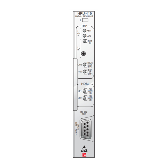
Page 12: Front Panel
Applications 150-419-100-03> RONT ANEL Figure 2 shows the HRU-419 front panel components. Table 3 describes the functions of the front panel components and Table 4 describes the status conditions indicated by the LEDs. HRU-419 HiGain REM UNIT LOS LEDs Loopback button Loopback (LB) LEDs B8ZS Code LEDs... -
Page 13: Table 2. Hru-419 Front Panel Components
150-419-100-03> Applications Table 2. HRU-419 Front Panel Components Name Function LOS LEDs Show Loss of Signal (LOS) alarm states (see Table 3 on page 6 Table 4 on page Loopback Show loopback states (see Table 3 on page 6 LEDs Table 4 on page Loopback Provides the ability to perform loopback test procedures (see... -
Page 14: Table 3. Hru-419 Front Panel Component Functions
Applications 150-419-100-03> Table 3. HRU-419 Front Panel Component Functions Name Function LOS LEDs Remote and Local Loss Of Signal (LOS). REM LOS Displays remote (REM) LOS. LOC LOS Displays local (LOC) LOS. LB LEDs Loopback to/from the NET (Network) and to/from the CI. NET Displays NET loopback state. -
Page 15: Table 4. Reading The Hru-419 Front Panel Leds
150-419-100-03> Applications Table 4. Reading the HRU-419 Front Panel LEDs Name Description REM LOS Lights red when the LOS is detected at the T1 input to the remote HLU unit. This condition causes the HRU to transmit the AIS pattern towards the CPE. - Page 16 Applications 150-419-100-03> Table 4. Reading the HRU-419 Front Panel LEDs (Cont.) Name Description Blinks green when HDSL Loop 1 is synchronizing with the HLU. Lights green when HDSL Loop 1 is synchronized and ready to receive and transmit data. Blinks yellow when a problem in Loop 1 (doubler applications only) of the HDSL cable pairs that are non-adjacent to the HRU.
-
Page 17: Compatibility
#343-00 (12-14 slot wire wrap) Charles Industries #319-02 (22 slot connectorized) Charles Industries #319-04 (22 slot wire wrap) Charles Industries #340-00 (9-11 slot wire wrap) ADC HMS-318 22-slot, 19-inch shelf ADC HHS-319 Three-slot, 19-inch horizontal shelf ADC HMS-317 28-slot, 23-inch shelf ADC HMS-308... -
Page 18: Local And Line Powering
Applications 150-419-100-03> OCAL AND OWERING The HRU-419 unit can be line or local powered. The unit always uses the local -48 V power source if it is present, and defaults to line power in the absence of local power. List 6 and higher versions of the HLU-231, and all versions of the HLU-319 and HLU-388, and versions 6.4 and above of the HLU-231 List 1, 2, 3, 3A and 4 units automatically turn off their line power supply when connected to a locally powered HRU-419. -
Page 19: Three-Span Line Powering
HIPMENT When you receive the equipment, inspect it for signs of damage. If the equipment has been damaged in transit, immediately report the extent of damage to the transportation company and to ADC. Your shipment should consist of: • One HRU-419 List 1 •... -
Page 20: Installing The Hru-419
150-419-100-03> HRU-419 NSTALLING THE The HRU-419 mounts in an STS-3192 High Density shelf or in equivalent card shelves manufactured by ADC Telecommunications (HHS-319, HMS-317 and HMS-308). To install the HRU-419 (Figure 3), Set the user options as described in the... -
Page 21: Connecting To A Maintenance Terminal
150-419-100-03> Installation ONNECTING TO A AINTENANCE ERMINAL The 9-pin RS-232 connector on the front of the HRU-419 allows you to connect your system to a maintenance terminal or PC running a terminal emulation program with a standard RS-232 cable. Once connected to a maintenance terminal, you can access the view-only Maintenance and Remote Terminal menus (the Set Clock option is the only user-configurable option on the HRU-419). -
Page 22: Figure 5. Connecting The Hru-419 To A Maintenance Terminal
Installation 150-419-100-03> ASCII terminal HRU-419 9-pin COM port Card shelf Interface cable Figure 5. Connecting the HRU-419 to a Maintenance Terminal September 25, 1998 HRU-419 List 1... -
Page 23: Card Edge Pinout Connector
150-419-100-03> Installation ARD EDGE PINOUT CONNECTOR The HRU-419 card edge connector pinout orientation is shown in Figure Table 6 provides the card edge connector pinouts. Figure 6. HRU-419 Card Edge Connector Pinout HRU-419 List 1 September 25, 1998... -
Page 24: The Hru-419 Circuit Board
Installation 150-419-100-03> Table 6. HRU-419 Card Edge Connector Pinouts Pin (*) Signal Description Pin (*) Signal Description DS1_T_TIP DS1_T_RING DS1 Transmit Transmit Tip Ring DS1_R_TIP DS1 Receive DS1_R_RING DS1 Receive Ring Tip 1 CIRCUIT GND Circuit Ground HDSL_TIP_A HDSL Loop HDSL_RING_A HDSL Loop 1 1 (Tip1) -
Page 25: Figure 7. Hru-419 Circuit Board Connections For User Options
150-419-100-03> Installation ENBL RLEV TLOS-LB I-CPE JP2-JP4 SCURR Figure 7. HRU-419 Circuit Board Connections for User Options HRU-419 List 1 September 25, 1998... - Page 26 Installation 150-419-100-03> Sealing Current (SCURR-JP1). The two-prong male JP1 jumper allows you to disable or enable the sealing current. The default is disable. To set the sealing current, do one of the following: • To enable the sealing current, connect JP1 across both terminals using the supplied female jumper block header.
-
Page 27: The Maintenance And Remote Terminal
150-419-100-03> Installation If you set the TLOS-LB switch to enable prior to entering a loopback state, the HRU transmits the AIS signal towards the CPE and returns the network signal back to the network. The HLU displays the message "TLOS" in its four-character front panel LCD. -
Page 28: Figure 8. Maintenance Terminal Main Menu
Installation 150-419-100-03> To use the Microsoft Windows terminal emulation program from the Settings Terminal Preference menu, you must deselect Show Scroll Bars and Use Function, Arrow, and Ctrl Keys for Windows. HI-GAIN HRU-419 MAINTENANCE TERMINAL MAIN MENU (ver V4.OR-0001)) A. VIEW SPAN STATUS B. -
Page 29: Figure 9. Remote Terminal Log In Screen
150-419-100-03> Installation Figure 9. Remote Terminal Log in Screen HI-GAIN HLU-419 REMOTE TERMINAL MAIN MENU (ver V2.2L-002D) CIRCUIT ID#:PairGain A. VIEW SPAN STATUS C. SYSTEM SETTINGS E. VIEW PERFORMANCE DATA F. VIEW PERFORMANCE HISTORY G. VIEW ALARM HISTORY H. REMOTE LOGOFF Figure 10. -
Page 30: Table 7. Maintenance And Remote Terminal Navigational Keys
Installation 150-419-100-03> Navigating the Maintenance and Remote Terminal menus. Table 7 describes the navigational keys for the Maintenance and Remote Terminal menus. Table 7. Maintenance and Remote Terminal Navigational Keys Function Logs into the Remote Terminal menus ENTER Exits the current menu Updates a report Selects the next Span Status screen Selects the previous page of a report... -
Page 31: Maintenance And Remote Terminal
150-419-100-03> Installation AINTENANCE AND EMOTE ERMINAL The Maintenance and Remote terminal menus have five view-only performance screens for viewing system performance. Table 8 describes the function of each screen. Table 8. Maintenance and Remote Terminal Menus Screen Function View Span Status Allows you to monitor the HDSL line between the HLU and the HRU-419 span (non-doubler applications), and the HLU, HDU and HRU-419,... -
Page 32: View Span Status
Installation 150-419-100-03> Non-Doubler Applications. The Maintenance Terminal Main menu displays for non-doubler applications. Press the SPACEBAR several times to initiate the RS-232 Craft port. View Span Status The View Span Status screen allows you to view the system status from the HLU to the HRU-419. - Page 33 150-419-100-03> Installation Doubler Applications: HDU 1 (one doubler) and HDU2 (two doublers) appear in the Span Status screen for doubler applications. Press from the Remote Terminal Main Menu to view the Span Status screen for single doubler applications: You can do the following: •...
-
Page 34: Figure 12. Span 3 Status For Two Doublers Application
Installation 150-419-100-03> SPAN 3 STATUS (HDU2/ver3.0-00FF: HRU/ver4.0-00FF) TIME: 05:22:36 DATE: 06/11/97 Circuit ID#: PairGain ALARMS: NONE LOOPBACK: OFF HDU2 HDSL-1 HDSL-2 HDSL-1 HDSL-2 cur/min/max cur/min/max cur/min/max cur/min/max MARGIN: 21/18/22 21/18/22 21/20/23 22/20/23 PULSE ATTN: PPM OFFSET: 24 HOUR ES: 00008 00007 00012 00009... -
Page 35: Table 9. Span Status Fields And Descriptions
150-419-100-03> Installation Table 9. Span Status Fields and Descriptions Field Description HLU/Ver w.x-y "w.x" = the software version number of the HLU. "y" = List # of the HLU. HRU or “w.x” = the software version number of the HRU or HDU. “y” = List # of HDU/w.x-y the HRU or HDU. -
Page 36: Table 10. Hru-419 Alarm Field Messages And Descriptions
Installation 150-419-100-03> Table 10. HRU-419 Alarm Field Messages and Descriptions Message Full Name Description NONE No Alarms No alarm conditions present in system. LLOS Local Loss No signal from HRUs T1 interface. of Signal LOSW Loss of One of the HDSL loops has lost synchronization. Sync Word H1ES HDSL Loop... -
Page 37: Table 11. Hru-419 Loopback Field Messages And Descriptions
150-419-100-03> Installation Table 11. HRU-419 Loopback Field Messages and Descriptions Message Full Name Description TLOS Transmit HRU logic loopback initiated by a loss of the T1 input from the Loss of Signal SMJK SmartJack Loopback at HRU towards network initiated by 2-in 5-in-band Loopback loopback code or out-of-band ESF data link code when SMJK is enabled. -
Page 38: Set Clock
Installation 150-419-100-03> Set Clock Press from the Maintenance Terminal Main menu to open the Set Clock menu: SET CLOCK TIME: 05:34:02 DATE: 06/18/97 Format: HH:MM MM/DD/YY NEW TIME: Figure 13. Set Clock Menu Set Time. The cursor defaults to the New Time field. To set the system time, type the hour and minute in the 24-hour format of hh:mm:ss (setting the ENTER seconds is optional), then press... -
Page 39: System Settings
150-419-100-03> Installation System Settings The System Settings screen allows you to view configurable parameters set at the HLU. Press from either the Maintenance Terminal Main Menu or the Remote Terminal Main menu to view the System Settings screen. SYSTEM SETTINGS TIME: 05:34:58 DATE: 06/18/97 EQUALIZATION..: 399... -
Page 40: Table 12. System Settings Fields And Descriptions
Installation 150-419-100-03> Table 12. System Settings Fields and Descriptions Field Description Time Time of day when System Settings were checked. Date Date when System Settings were checked. Equalization Indicates settings for equalizer of either 0 (DSX-1 for 0-133 ft), 133 (DSX-1 for 133-266 ft), 266 (DSX-1 for 266-399 ft), 399 (DSX-1 399-533 ft), 533 DSX-1 for 533-655 ft). -
Page 41: View Performance Data
150-419-100-03> Installation View Performance Data The View Performance Data screen shows the number of ES and UAS occurrences in 15-minute increments for a 24-hour period. The presentation format is: ES/UAS (Errored Seconds/Unavailable Seconds) for the HLU and the HRU-419 for the DS1 signal, HDSL Loop 1 and HDSL Loop 2 (non-doubler applications). -
Page 42: Figure 16. Span 1 Perfromance Data Screen
Installation 150-419-100-03> The HDU 1 (one doubler) and HDU2 (two doublers) appear in the Span Status screen for doubler applications. Press from the Remote Terminal Main menu to view the Span 1 Performance Data screen. Date: 06/11/97 SPAN 1 PERFORMANCE DATA CIRCUIT ID#: PairGain ERRORED SECONDS/UNAVAILABLE SECONDS HDSL-1... -
Page 43: Figure 17. Span 2 Perfromance Data Screen
150-419-100-03> Installation Date: 06/11/97 SPAN 2 PERFORMANCE DATA CIRCUIT ID#: PairGain ERRORED SECONDS/UNAVAILABLE SECONDS HDSL-1 HDSL-2 01:45 000/000 000/000 000/000 000/000 000/000 000/000 02:00 000/000 000/000 000/000 000/000 000/000 000/000 02:15 000/000 001/000 001/000 001/000 001/000 001/000 02:30 000/000 000/000 000/000 000/000 000/000... - Page 44 Installation 150-419-100-03> The presentation format is: ES/UAS for the HLU and the HRU-419 DS1 signal, and ES/UAS for the HLU and HDU1 over both HDSL Loop 1 and HDSL Loop 2. • You can do the following: • Press to view the previous screen. •...
-
Page 45: View Performance History
150-419-100-03> Installation View Performance History The View Performance History screen shows the number of ES and UAS occurrences in 24-hour increments for a seven-day period. The presentation format is: ES/UAS for the HLU and the HRU-419 DS1 signal, HDSL Loop 1 and HDSL Loop 2 (for non-doubler applications). -
Page 46: Figure 19. 7 Day History Span 2
Installation 150-419-100-03> Time: 05:57:43 7 DAY HISTORY CIRCUIT ID#: PairGain Span 1 ERRORED SECONDS/UNAVAILABLE SECONDS HDSL-1 HDSL-2 06/04 00000/00000 00000/00000 00000/00000 00000/00000 00000/00000 00000/00000 06/05 00000/00000 00000/00000 00000/00000 00000/00000 00000/00000 00000/00000 06/06 00000/00000 00000/00000 00000/00000 00000/00000 00000/00000 00000/00000 06/07 00000/00000 00000/00000 00000/00000 00000/00000 00000/00000 00000/00000 06/08 00000/00000 00000/00000 00000/00000 00000/00000 00000/00000 00000/00000 06/09... -
Page 47: View Alarm History
150-419-100-03> Installation View Alarm History The View Alarm History screen allows you to view alarms that are currently active. Non-Doubler Applications. Press from the Maintenance Terminal Main menu to view the Alarm History screen for non-doubler applications: Time: 00:16:55 7 DAY HISTORY CIRCUIT ID#: SPAN 1 ERRORED SECONDS/UNAVAILABLE SECONDS... -
Page 48: Remote Logoff
Installation 150-419-100-03> Table 13. Alarm History Fields and Descriptions Field Description Type Identifies the type of alarm. LOS, First and last instance of LOS at the HLU; Current condition, number of DS1-HLU alarms. LOS, First and last instance of LOS at the HRU; Current condition, number of DS1-HRU alarms. -
Page 49: Loopbacks
150-419-100-03> Loopbacks OOPBACKS This section contains information for loopbacks and testing. Loopbacks allow you to perform isolated diagnostic tests on specific areas of the circuit. The transmitted signal is returned to the sending device after passing through a data communications link or network. This allows you to compare the returned signal with the transmitted signal and to determine if there is a problem with the circuit. -
Page 50: Figure 21. Hru-419 Loopbacks
Loopbacks 150-419-100-03> HRU-419 HDSL LOGIC TLOS HRU-419 HDSL 3 in 7 NREM HRU-419 Loopbacks towards HDSL 2 in 5 network SMJK HRU-419 4 in 7 HDSL NLOC DSX-1 HRU-419 NDU1 NDU2 HRU-419 HDSL CREM HRU-419 Loopbacks towards HDSL 5 in 7 customer CLOC HRU-419... -
Page 51: Loopbacks Toward The Network
150-419-100-03> Loopbacks OOPBACKS OWARD THE ETWORK The HiGain loopbacks toward the network are as follows: • Transmit Loss of Signal (TLOS): An HRU logic loopback initiated by a loss of the T1 input from the CI. • Network Remote (NREM): The DSX signal is looped back to the DSX at the HRU. -
Page 52: Smartjack (Smjk) Loopback
Loopbacks 150-419-100-03> (SMJK) L MART OOPBACK The SmartJack loopback shown in Figure 21 is the standard NID metallic loopback. It has two modes of operation as determined by the SAIS user option settings at the HLU (ENA or DIS). The ENA option causes the HRU to transmit the AIS signal towards the NI. -
Page 53: Sais Set To Dis
150-419-100-03> Loopbacks HLU Code option is set to either AUTO or AMI. The HRU LED indicates B8ZS if the Code option is set to B8ZS. The AIS/ENA metallic loopback scenario includes and therefore tests all HiGain active circuits and fully conforms with TR-TSY-000312. In this sense it outperforms the loopback function found in most standard NID devices, since these devices, do not include either the AIS generator or the CI T1 LOS detector in their loopback path. -
Page 54: Loss Of Sync Word (Losw) Conditions
Loopbacks 150-419-100-03> (LOSW) C OSS OF ONDITIONS The HAIS option provides two choices for the T-1 transmit outputs at both the HLU and HRU for HDSL loss of sync conditions. HAIS S ET TO The 1 Loop choice causes the AIS pattern to be transmitted at both T-1 outputs when either of the two HDSL loops experience an out-of-sync (LOSW) condition or when a margin alarm occurs. - Page 55 150-419-100-03> Loopbacks If trouble is encountered at the T1 interface, verify that the unit is making a positive connection with the mounting assembly connector. Press the loopback LB button on the HRU front panel for at least five seconds. Verify that the Green HRU front panel loopback LB NET LED turns on, indicating that the HRU is in its digital (NREM) loopback state.
-
Page 56: Appendix A- Technical Specifications
Appendix A- Technical Specifications 150-419-100-03> A- T PPENDIX ECHNICAL PECIFICATIONS Physical Material Steel Finish Zinc plated Mounting STS, 3192 High Density Dimensions Height 4.75 in. (12.06 cm) Width 0.70 in. (1.78 cm) Depth 10.5 in. (26.67 cm) Weight 0.5 lb. (0.23 kg) Power Consumption 4.5 W (with I-CPE set to 0), 6.3 W (with... -
Page 57: Functional Description
150-419-100-03> Appendix A- Technical Specifications Delay (one-way) <220 µs per span 100 Ω Line Impedance Pulse Output 0 dB (RLEV = 0), -15 dB (RLEV = -15) Input Level > - 22.5 dB Line Rate 1.544 Mbps ± 200 bps Output Wander (MTIE and TVAR) Compliant with Section 7.2.1 of the... -
Page 58: Figure 22. Hru-419 Block Diagram
Appendix A- Technical Specifications 150-419-100-03> E, H, C, D, L, 3, 4 Not used RLEV HDSL 1 HDSL 1 FRAMER XCVR ( - ) ( + ) DS1/RCV LOGIC LOOPBACK SEALING CLOC,TLOS METALLIC POWER SUPPLY CURRENT I-CPE 48V* LOOPBACK OPTION SMJK NREM 60 mA MON... -
Page 59: Appendix B- Abbreviations
150-419-100-03> Appendix B- Abbreviations B- A PPENDIX BBREVIATIONS 2–Bits–1–Quaternary 2B1Q Alarm Indication Signal Alternate Mark Inversion Bipolar 8-Zero Substitution B8ZS Bipolar Violation Customer Interface Customer Premises Equipment Cyclic Redundancy Check Carrier Service Area Channel Service Unit Data Circuit-Terminating Equipment High-bit-rate Digital Subscriber Line HDSL HiGain Doubler Unit HiGain Line Unit... - Page 60 Appendix B- Abbreviations 150-419-100-03> Network Interface Device Plain Old Telephone Service POTS Receive Level RLEV Sealing Current SCURR Signal-to-Noise Special Loopback SPLB Transmit Loss of Signal TLOS Transport System Generic Requirements TSGR September 25, 1998 HRU-419 List 1...
-
Page 61: Appendixc - Product Support
C - P PPENDIX RODUCT UPPORT ADC Customer Service Group provides expert pre-sales and post-sales support and training for all its products. Technical support is available 24 hours a day, 7 days a week by contacting the ADC Technical Assistance Center. - Page 62 Appendix C - Product Support 150-419-100-03> Product Return Department • ADC Return Material Authorization (RMA) number and instructions must be obtained 800.366.3891 extension 73748 or before returning products. 952.917.3748 Fax: 952.917.3237 Email: repair&return@adc.com All telephone numbers with an 800 prefix are toll-free in the USA and Canada.
- Page 63 Customer Service for details. ODIFICATIONS Any changes or modifications made to this device that are not expressly approved by ADC DSL Systems, Inc. voids the user's warranty. All wiring external to the products should follow the provisions of the current edition of the National Electrical Code.
- Page 64 ADC DSL Systems, Inc. 14402 Franklin Avenue Tustin, CA 92780-7013 Tel: 714.832.9922 Fax: 714.832.9924 Technical Assistance Tel: 800.366.3891 x73223 Tel: 952.917.3223 Fax: 952.917.3244 : 150-419-100-03> OCUMENT ´,ZW¶4j¨ 1258554...
Need help?
Do you have a question about the HRU-419 HiGain and is the answer not in the manual?
Questions and answers