Sign In
Upload
Manuals
Brands
Metrohm Manuals
Laboratory Equipment
761 SD Compact IC
Metrohm 761 SD Compact IC Manuals
Manuals and User Guides for Metrohm 761 SD Compact IC. We have
1
Metrohm 761 SD Compact IC manual available for free PDF download: Instructions For Use Manual
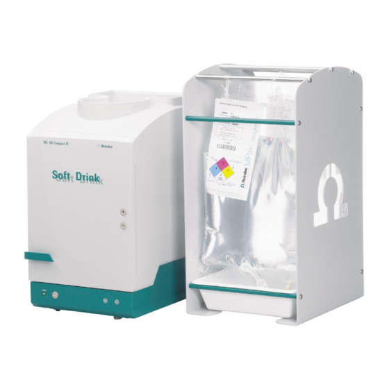
Metrohm 761 SD Compact IC Instructions For Use Manual (135 pages)
Brand:
Metrohm
| Category:
Laboratory Equipment
| Size: 3 MB
Table of Contents
Table of Contents
5
Introduction
9
Instrument Description
9
Parts and Controls
11
Front View
11
Figure 1: Front of the 761 SD Compact IC
11
Rear View
12
Figure 2: Rear Panel 761 SD Compact IC
12
Connection Schematic
13
Figure 3: Connection Schematic for 761 SD Compact IC
13
Information on the Instructions for Use
15
Organisation
15
Notation and Pictograms
16
Safety Notes
17
Electrical Safety
17
General Precautionary Rules
17
Installation
18
Flow Chart
18
Setting up the Instrument
19
Packaging
19
Check
19
Location
19
Description of the Connections
20
Connection of Capillaries/Tubing
20
Connection between Capillaries/Tubing
21
Figure 4: Connectors for Capillaries
21
Figure 5: PEEK Couplings
21
Filter Unit PEEK
22
Figure 6: Connecting the Filter Unit PEEK
22
Connection of the Detector Block
23
Figure 7: Position of the Detector Block 40
23
Installation of the Mpak Cabinet and Connection of the Drain Tubes
24
Installing the Mpak Cabinet
24
Drain Tube for Inner Compartment
24
Drain Tube for Mpak Cabinet
24
Installing the Eluent Path
25
High-Pressure Pump - Removing the Transport Security Screws
25
Connection Mpak → High-Pressure Pump
25
Connection High-Pressure Pump → Injection Valve
26
Connection Injection Valve → Suppressor
27
Connection Suppressor → Detector
27
Connection Detector → Suppressor
27
Connection Suppressor → Waste
28
Installing the Regenerant Path
28
Fitting the Pump Tubing for Regenerant
28
Connection Regenerant-Mpak → Pump Tubing → Suppressor → Waste
29
Figure 8: Pump Tubing for Regenerant Path
29
Figure 9: Flow Schematic Regenerant Flow
30
Installing the Sample Path
31
Fitting the Pump Tubing for Sample
31
Connection Sample Vessel → Pump Tubing → Injection Valve → Waste
32
Figure 10: Pump Tubing for Sample Path
32
Figure 11: Flow Schematic Sample Stream
33
Connecting the 766 IC Sample Processor
34
Installing the 766 IC Sample Processor
34
Fitting the Rear Panel
35
Figure 12: Rear Panel
35
Mains Connections
36
Setting the Mains Voltage
36
Fuses
37
Mains Cable and Mains Connection
37
Switching the Instruments On/Off
37
Figure 13: Setting the Mains Voltage
37
Connection to the PC
38
Connecting Cable 6.2134.100
38
Software Installation
38
Basic Settings "IC Net
39
Basic Settings "IC Cap
41
Deaerating the Pump and Rinsing the Pulsation Dampener
42
Deaerating the Pump
42
Rinsing the Pulsation Dampener
43
Rinsing before Fitting the Column
45
Precolumn and Separating Column
47
Metrosep RP Guard
47
Metrosep a Supp 1 HS Separating Column
48
Figure 14: Connection of Precolumn and Separating Column
49
Attaching Tubing to Side Panels
50
IC Net
51
IC Net" - User Interface for the 761 SD Compact IC
51
Systems - Methods
51
Opening a System
51
Opening a Method
52
Connect a System
52
Instrument Icon
53
System Parameters for Linked System
53
Hardware Settings
58
Systems Supplied
62
System "Startup.smt
62
System "Manual.smt
63
System "Auto.smt
64
System "Shutdown.smt
69
IC Cap
72
IC Cap" Introduction
72
Login
72
User Interface
72
IC Cap" - Configuration
74
Predefined Configurations
74
Configuration "Manual.cfg
74
Configuration "Auto.cfg
80
Operation
85
Operation with Manual Sample Change
85
Control with "IC Net" (Manual Operation)
85
Control with "IC Cap" (Manual Operation)
89
Operation with Automated Sample Change
92
Control with "IC Net" (Automated Operation)
92
Control with "IC Cap" (Automated Operation)
94
Notes - Maintenance - Faults
96
Practical Notes on Ion Chromatography
96
Separating Columns
96
High-Pressure Pump
96
Eluents
97
Peristaltic Pump
97
Suppressor Module
97
Connections
98
Maintenance and Servicing
99
General Information
99
Passivation
99
Shutdown
99
Changing Separating Columns
100
Maintenance Work on the Pump Head
100
Figure 15: Components of the Pump Head
102
Figure 16: Replacement of the Piston Seal 76
102
Figure 17: Components of Inlet Valve 77 and Outlet Valve 78
105
Regeneration of the Suppressor Module
106
Cleaning the Suppressor
108
Figure 18: Assembling the Suppressor
109
Replacing the Suppressor
110
Replacing the Pump Tubing
111
Faults and Malfunctions
112
Error Messages
112
Malfunctions and Their Rectification
112
Diagnostic Tests / Validation / GLP
114
Appendix
115
Technical Data
115
Conductivity Measurement
115
Conductivity Detector
115
Injection Valve
116
High-Pressure Pump
116
Peristaltic Pump
117
Suppressor Module
117
Leak Detector
117
RS232 Interface
117
Remote Interface
118
Mains Connection
118
Safety Specifications
119
Electromagnetic Compatibility (EMC)
119
Ambient Temperature
119
Housing
119
Standard Equipment
120
Optional Accessories
126
6.5328.000 SD Spare Part Set
126
Other Optional Accessories
128
Warranty and Conformity
129
Warranty
129
Declaration of Conformity
130
Quality Management Principles
131
Index
132
Advertisement
Advertisement
Related Products
Metrohm 761 Compact IC
Metrohm 768 KF Oven
Metrohm 763 PVC Thermomat
Metrohm 762 IC Interface
Metrohm 760
Metrohm 751 GPD Titrino
Metrohm 776 Dosimat
Metrohm 798 MPT Titrino
Metrohm 717
Metrohm 785 DMP Titrino
Metrohm Categories
Laboratory Equipment
Measuring Instruments
Security Sensors
Control Unit
Medical Equipment
More Metrohm Manuals
Login
Sign In
OR
Sign in with Facebook
Sign in with Google
Upload manual
Upload from disk
Upload from URL