Table of Contents
Advertisement
Quick Links
SD card real time Data Recorder
200 mbar, differential manometer
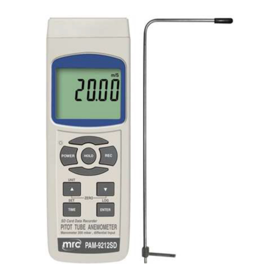
PITOT TUBE ANEMOMETER
Model : PAM-9212SD
OPERATION MANUAL
PLEASE READ THIS MANUAL CAREFULLY BEFORE OPERATION
Hagavish st. Israel 58817 Tel: 972 3 5595252, Fax: 972 3 5594529
Your purchase of this
PITOT TUBE ANEMOMETER
with SD CARD DATA LOGGER
marks a step forward for you
into the field of
precision measurement.
Although this meter a
complex and delicate
instrument, its durable
structure will allow
many years of use if
proper operating
techniques are
developed. Please read
the following
instructions carefully
and always keep this
manual within easy
reach.
MRC.5.22
mrc@mrclab.com
Advertisement
Table of Contents

Related Manuals for MRC PAM-9212SD


Summary of Contents for MRC PAM-9212SD
- Page 1 SD card real time Data Recorder 200 mbar, differential manometer PITOT TUBE ANEMOMETER Model : PAM-9212SD Your purchase of this PITOT TUBE ANEMOMETER with SD CARD DATA LOGGER marks a step forward for you into the field of precision measurement.
-
Page 2: Table Of Contents
TABLE OF CONTENTS 1. FEATURES..................1 2. SPECIFICATIONS................ 2-1 General Specifications..............2-2 Electrical Specifications................ 3. FRONT PANEL DESCRIPTION................4. MEASURING PROCEDURE............... 5. DATALOGGER....................5-1 Preparation before execute datalogger function........... 5-2 Auto Datalogger ( Set sampling time ≧ 1 second )..........5-3 Manual Datalogger ( Set sampling time = 0 second )......... -
Page 3: Features
1 FEATURES * Pitot tube Anemometer measurements for Air Velocity . * Dual & differential input, ± 200 mbar max. range. * Application : Industrial, laboratory, heating, ventilation, medical hospital, used for air or not corrosive and not ionized gas & liquid. * Sensor is built inside the housing. -
Page 4: Specifications
2. SPECIFICATIONS 2-1 General Specifications Circuit Custom one-chip of microprocessor LSI circuit. Display LCD size : 51 mm x 37 mm LCD with green backlight ( ON/OFF ). Display units Air vilocity : m/s, km/h, FPM, mph, knots Air pressure: psi , inch Hg , inch H2O , h PA , kPA mbar, Kg/cm , mm Hg , meter H2O , Atmosphere. - Page 5 Data Hold Freeze the display reading. Memory Recall Maximum & Minimum value. Sampling Time Approx. 1 second. of Display Data Output RS 232/USB PC computer interface. * Connect the optional RS232 cable UPCB-02 will get the RS232 plug. * Connect the optional USB cable USB-01 will get the USB plug.
-
Page 6: Electrical Specifications
Optional SD memory card ( 4 GB ) Accessories AC to DC 9V adapter. USB cable, USB-01. RS232 cable, UPCB-02. Data Acquisition software,SW-U801-WIN. ℃ 2-2 Electrical Specifications (23±5 Air velocity Measurement Range Resolution Accuracy 4.1 to 100.0 m/s 0.1 m/s ±( 3% + a ) reading Km/h... - Page 7 Manometer Unit Max. range Resolution mbar ± 200 mbar mbar ± 2.9 0.01 ± 0.2 0.001 Kg/cm Kg/cm Kg/cm mm Hg ± 150 mm Hg mm Hg inch Hg ± 5.91 inch Hg 0.02 inch Hg ± 2.040 0.01 meter H O...
- Page 8 Remark : Measuring Display unit unit inch Hg In Hg inch H O In H2O h PA h PA _ PA mbar - bAr _ g C2 Kg/cm mm Hg - - Hg meter H O - t H2O Atmosphere...
-
Page 9: Front Panel Description
3. FRONT PANEL DESCRIPTION Fig. 1 Display 3-12 RS-232 Output Terminal Power Button 3-13 Reset Button Hold Button / Backlight Button 3-14 DC 9V Power Adapter Input Socket REC Button 3-15 Battery Compartment/Cover UNIT Button , ▲ Button 3-16 Battery Cover Screws Function Button , ▼... -
Page 10: Measuring Procedure
4. MEASURING PROCEDURE A.Air vilocity 1) Power ON the meter by pressing and holding the " Power Button " ( 3-2, Fig. 1 )for at least 1.5 seconds . * Pressing the " Power Button " ( 3-2, Fig. 1 ) continuously and >... - Page 11 B. Manometer 1) Power ON the meter by pressing and holding the " Power Button " ( 3-2, Fig. 1 )for at least 1.5 seconds . * Pressing the " Power Button " ( 3-2, Fig. 1 ) continuously and >...
- Page 12 REMARK: Pressure quick connector use : 1)connect with the meter pressure quick connector, you can insert directly. 2)To disengage from the meter, the pressure quick connector has a slide device, slide it to the last position, then Pull out. 7) Data Hold During the measurement, press the "...
- Page 13 For quick measurement, follow the procedures shown below : Main procedures : POWER ZERO ADJUST DETERMINE UNIT Optional measuring procedures : DATA HOLD MEMORY RECORD RS232 OUTPUT Max., Min. datalogger function Auto datalogger function Manual datalogger function Power management AUTO POWER OFF MANUAL POWER OFF (Not activated during Memory Record Selection)
-
Page 14: Datalogger
5. DATALOGGER 5-1 Preparation before execute datalogger function a. Insert the SD card Prepare a " SD memory card "( 1 GB to 16 GB, optional ) insert the SD card into the "SD card Socket" ( 3-11, Fig. 1 ).The front panel of the SD card should face against the down case. -
Page 15: Manual Datalogger ( Set Sampling Time = 0 Second )
Remark : How to set the sampling time, refer to Chapter 7-2 , page 19 . How to set the beeper sound is enable, refer to Chapter 7-4, page 20 . b. Pause the datalogger During execute the Datalogger function, if press the "... -
Page 16: To Check The Time And Sampling Time Information
Remark : During execute the Manual Datalogger, it can use the " ▲ Button " ( 3-5, Fig. 1) or " Button " ( 3-6, Fig. 1 ) to ▼ set the measuring position ( 1 to 99, for example room 1 to room 99 ) to identify the measurement location , the lower Display will show P x ( x = 1 to 99 ). - Page 17 3) Under the folder PMA01\, if the total files more than 99 files, will generate anew route, such as PMA02\ ..4) The file's route structure : PMA01\ PMA01001.XLS PMA01002.XLS ..... PMA01099.XLS PMA02\ PMA02001.XLS PMA02002.XLS ..... PMA02099.XLS PMAXX\ .......... Remark : XX : Max.
-
Page 18: Saving Data From The Sd Card To The Computer ( Excel Software )
6. Saving data from the SD card to the computer ( EXCEL software ) 1) After execute the Data Logger function, take away the SD card out from the " SD card socket " ( 3-11, Fig. 1 ). 2) Plug in the SD card into the Computer's SD card slot ( if your computer build in this installation ) or insert the SD card into the "... - Page 19 EXCEL graphic screen ( for example, graphic )
-
Page 20: Advanced Setting
7. ADVANCED SETTING Under do not execute the Datalogger function, press the " SET Button " ( 3-7, Fig. 1 ) continuously at least two seconds will enter the " Advanced Setting " mode. then press the " SET Button " ( 3-7, Fig. 1 ) once a while in sequence to select the six main function, the display will show : DATE.. -
Page 21: Set Sampling Time (Hour/Minute/ Second )
Remark : The adjusted value will be flashed. 2) After set all the time value ( Year, Month, Date, Hour, Minute, Second ), press the " SET Button " ( 3-7, Fig. 1 ) once will save the time value, then the screen will jump to Sampling time "... -
Page 22: Set Beeper Sound On/Off
YES - Auto Power Off management will enable. no - Auto Power Off management will disable. 2) After select the upper text to " YES " or " no ", press the " Enter Button " ( 3-8, Fig. 1 ) will save the setting function with default. -
Page 23: Sd Memory Card Format
2) After select the upper text to " USA " or " EURO ", press the " Enter Button " ( 3-8, Fig. 1 ) will save the setting function with default. 7-6 SD memory card Format When the lower display show " Sd F " 1) Use the "... -
Page 24: Power Supply From Dc Adapter
8. POWER SUPPLY from DC ADAPTER The meter also can supply the power supply from the DC 9V Power Adapter ( optional ). Insert the plug of Power Adapter into " DC 9V Power Adapter Input Socket " ( 3-14, Fig. 1 ). The meter will use the DC ADAPTER power supply . -
Page 25: Rs232 Pc Serial Interface
11. RS232 PC SERIAL INTERFACE The instrument has RS232 PC serial interface via a 3.5 mm terminal ( 3-12, Fig. 1 ). The data output is a 16 digit stream which can be utilized for user's specific application. A RS232 lead with the following connection will be required to link the instrument with the PC serial port. - Page 26 The 16 digits data stream will be displayed in the following format : D15 D14 D13 D12 D11 D10 D9 D8 D7 D6 D5 D4 D3 D2 D1 D0 Each digit indicates the following status : Start Word When send the upper display data = 1 When send the lower display data = 2 D12, D11 Annunciator for Display...
-
Page 27: Optional Accessories
12. OPTIONAL ACCESSORIES Mmory card SD memory card ( 4GB ) RS232 cable * Computer interface cable. UPCB-02 * Used to connect the meter to the computer ( COM port ). USB cable * Computer interface cable. USB-01 * Used to connect the meter to the computer ( USB port ). -
Page 28: Patent
13. PATENT The meter ( SD card structure ) already get patent or patent pending in following countries : Germany Nr. 20 2008 016 337.4 JAPAN 3151214 TAIWAN M 358970 M 359043 CHINA ZL 2008 2 0189918.5 ZL 2008 2 0189917.0 Patent pending...
Need help?
Do you have a question about the PAM-9212SD and is the answer not in the manual?
Questions and answers