Table of Contents
Advertisement
Quick Links
Advertisement
Table of Contents

Related Manuals for Bender RDC104-4


Summary of Contents for Bender RDC104-4
- Page 1 RDC104-4 Gleichstromsensitives Differenzstrom-Überwachungsmodul für Ladesysteme für Elektrofahrzeuge DC sensitive residual current monitoring module for electric vehicle charging systems RDC104-4_D00402_02_M_DEEN / 11.2021 Handbuch/Manual DE/EN...
-
Page 2: Allgemeine Hinweise
Verpackungsbeilage „Sicher- the enclosed „ Safety instructions for Bender products“. heitshinweise für Bender-Produkte“. Darüber hinaus sind die für den Einsatzort Furthermore, the rules and regulations geltenden Regeln und Vorschriften zur that apply for accident prevention at the Unfallverhütung zu beachten. - Page 3 Lieferbedingungen Delivery conditions Es gelten die Liefer- und Zahlungsbedingungen der Bender sale and delivery conditions apply. They can Firma Bender. Sie sind gedruckt oder als Datei bei be obtained from Bender in printed or electronic for- Bender erhältlich. mat. Für Softwareprodukte gilt: For software products applies: „Softwareklausel zur Überlassung von...
-
Page 4: Bestimmungsgemäße Verwendung
Bemessungsstrom (Ladestrom) I = 1 x 48 A/3 x 32 A. (charging current) I = 1 x 48 A/3 x 32 A. The RDC104-4 Das RDC104-4 ist als RDC-M-Modul zur Integration in is suitable for integration into a charging unit Mode 3 eine Ladeeinrichtung Mode 3 (AC) nach IEC 62955 ge- (AC) as a RDC-M module according to IEC 62955. -
Page 5: Safety Instruction
3S1 • 3S2 1S1 • 2S1 • 1S2 2S2 • = Wicklungsanfang/Start of winding Test Error n.c. RDC104-4 2,00 mm 23,99 mm 0,5 x 0,5 mm 26,50 mm 0,64 x 0,64 mm 28,00 mm Maßbild RDC104-4 Dimension diagram RCD104-4 RDC104-4_D00402_02_M_DEEN / 11.2021... -
Page 6: Functional Description
Gleichstromkomponente des Differenzstroms. DC component of the residual current. Das RDC104-4 meldet eine Grenzwertüberschreitung The RDC104-4 signals a limit value violation at the an den Ausgängen DC1 und DC2. Die Grenzwerte outputs DC1 and DC2. The limit values depend on the... -
Page 7: Example Wiring Diagram
Anschlussbuchse Messstromwandler measuring current transformer 1,6 mm 2,5 mm 6,5 mm Leiterplatte/ circuit board 2,5 mm Seitenansicht RDC104-4 / Side view RDC104-4 *Wicklungsanfang / Start of winding Empfohlener Bohrdurchmesser: Ø 1,1 mm Recommended drilling diameter: Ø 1,1 mm RDC104-4_D00402_02_M_DEEN / 11.2021... - Page 8 RDC104-4 Legende Legend Erklärung Auswerteplatine/ Anschluss Messstromwandler/ Description Evaluating board Connection Socket CT Prüfwicklung (Wicklungsanfang) Test winding (start of winding) Prüfwicklung Test winding Messwicklung 2 Measuring winding 2 (start of winding) (Wicklungsanfang) Messwicklung 1 Measuring winding 1 (start of winding)
-
Page 9: Device Test
Messstromwandler fließt! the measuring current transformers! Das RDC104-4 kann nur mit angeschlossenem The RDC104-4 can only be put into operation Wandler in Betrieb genommen und auch ge- and also tested with a connected measuring testet werden. Ohne Wandler kommt es zu ei- current transformer. - Page 10 RDC104-4 Gerätetest wird über eine externe The device test is initiated via an external control sys- Steuereinrichtung (Laderegler) initialisiert. Nach Start tem (charge controller). After starting the self test via des Selbsttests über den Digitaleingang „Test“ er- the digital input „Test“, the device generates a test zeugt das Gerät einen Prüfstrom.
- Page 11 Modul mit der Differenzstrommessung. Das be- initiates the residual current measurement. This me- deutet, dass das RDC104-4 frühestens nach Ablauf ans that the RDC104-4 can only detect a limit value der Zeit t = t nach Zuschalten der Versorgungs-...
-
Page 12: Power Supply
Auflösung I ..............< DC 0,2 mA Resolution I ..............< DC 0.2 mA Δn Δn Ansprechwerte Response values RDC104-4 (IEC 62955) RDC104-4 (IEC 62955) Bemessungsauslösefehlergleichstrom I ........6 mA Rated DC residual operating current I ........6 mA Δdc Δdc Ansprechwert I .............. -
Page 13: Degree Of Protection
EMV (DIN EN 61851-1, DIN EN 61851) EMV (DIN EN 61851-1, DIN EN 61851) Einschränkungen ESD: Das RDC104-4 muss in ein den genannten ESD restrictions: The RDC104-4 must be mounted in an enclosure Normen entsprechendes Gehäuse eingebaut werden. that complies with the mentioned standards. - Page 14 Molex. entnehmen. Normen Standards Das Gerät RDC104-4 entspricht den Gerätenormen: The device RDC104-4 series complies with the follo- wing device standards: 62955 (Fehlergleichstrom-Überwachungs- IEC 62955 (Residual direct current detecting device einrichtung zur Verwendung mit der Ladebetriebsart...
-
Page 15: Ordering Information
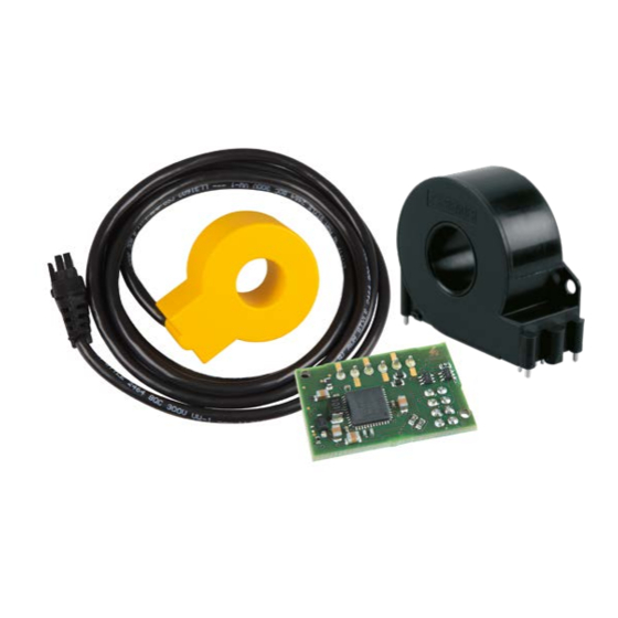
RDC104-4 Bestellangaben Ordering information Typ/Type Bezeichnung Description Art. Nr./Art. No. RDC104-4 RDC-M-Modul nach IEC 62955 RDC-M module acc. to IEC 62955 B94042483 W15BS Messstromwandler Ø = 15 mm, Measuring current transformer Ø = 15 mm, B98080065 Anschlussleitung 1470 ±30 mm Connection cable 1470 ±30 mm... - Page 16 Nachdruck und Vervielfältigung Reprinting and duplicating nur mit Genehmigung des Herausgebers. only with permission of the publisher. Bender GmbH & Co. KG Bender GmbH & Co. KG Postfach 1161 • 35301 Grünberg • Deutschland PO Box 1161 • 35301 Grünberg • Germany Londorfer Str.
Need help?
Do you have a question about the RDC104-4 and is the answer not in the manual?
Questions and answers