
Related Manuals for Bender RCMB423EM


Summary of Contents for Bender RCMB423EM
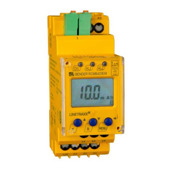
- Page 1 Manual RCMB423EM Residual current monitor for monitoring AC-, DC- and pulsed DC currents in TN- and TT systems Software version: D480 V1.01 RCMB423_D00241_01_M_XXEN/12.2016...
- Page 2 Bender GmbH & Co. KG P.O. Box 1161 • 35301 Gruenberg • Germany Londorfer Strasse 65 • 35305 Gruenberg • Germany Tel.: +49 6401 807-0 • Fax: +49 6401 807-259 E-Mail: info@bender.de • www.bender.de © Bender GmbH & Co. KG All rights reserved.
-
Page 3: Table Of Contents
Table of Contents 1. Important information ..................5 How to use this manual ................. 5 Technical support: service and support ........... 6 1.2.1 First level support ..................... 6 1.2.2 Repair service ..................... 6 1.2.3 Field service ......................7 Training courses ....................8 Delivery conditions .................. - Page 4 Table of Contents 4. Installation and connection ................. 17 5. Operation and configuration ..............19 Display elements in use ................19 Function of the operating elements ............20 Menu structure ....................21 5.3.1 Quick menu ..................... 22 5.3.2 Full menu ......................24 Parameter settings ..................
-
Page 5: Important Information
1. Important information 1.1 How to use this manual This manual is intended for qualified personnel working in electrical engineering and electronics! Always keep this manual within easy reach for future reference. To make it easier for you to understand and revisit certain sections in this man- ual, we have used symbols to identify important instructions and information. -
Page 6: Technical Support: Service And Support
Important information This manual has been compiled with great care. It might nevertheless contain errors and mistakes. Bender cannot accept any liability for injury to persons or damage to property resulting from errors or mistakes in this manual. 1.2 Technical support: service and support For commissioning and troubleshooting Bender offers you: 1.2.1... -
Page 7: Field Service
Important information Bender GmbH, Repair-Service, Londorfer Str. 65, 35305 Gruenberg 1.2.3 Field service On-site service for all Bender products Commissioning, configuring, maintenance, troubleshooting of Bender products Analysis of the electrical installation in the building (power quality test, ... -
Page 8: Training Courses
ZVEI (Zentralverband Elektrotechnik- und Elektronikindustrie e. V.) (German Electrical and Electron- ic Manufacturer's Association) also applies. Sale and delivery conditions can be obtained from Bender in printed or elec- tronic format. 1.5 Inspection, transport and storage Inspect the dispatch and equipment packaging for damage, and compare the contents of the package with the delivery documents. -
Page 9: Warranty And Liability
Important information 1.6 Warranty and liability Warranty and liability claims in the event of injury to persons or damage to property are excluded if they can be attributed to one or more of the follow- ing causes: Improper use of the device. ... -
Page 10: Disposal
13 August 2005 must be taken back by the manufacturer and disposed of properly. For more information on the disposal of Bender devices, refer to our homepage at www.bender-de.com -> Service & support. -
Page 11: Safety Instructions
2. Safety instructions 2.1 General safety instructions Part of the device documentation in addition to this manual is the enclosed "Safety instructions for Bender products". 2.2 Work activities on electrical installations Only qualified personnel are permitted to carry out the work necessary to install, commission and run a device or system. -
Page 12: Intended Use
Since the values are measured with measuring current transformers, the RCMB423EM is almost independent of the nominal voltage and the current of the monitored system. The response value I as well as the response delay t can be configured Δn2... -
Page 13: Function
3. Function 3.1 Device characteristics AC/DC sensitive residual current monitor type B acc. to IEC 62020 and IEC 60755 Quick menu: direct setting of the response value I as well as the Δn2 response delay t r.m.s. -
Page 14: Connection Monitoring
3.2.4 Malfunction In the event of an internal malfunction, all three LEDs will flash. The display shows an error code (E01…E32). In such a case please contact the Bender Ser- vice. 3.2.5 Delay times , The times t, t... -
Page 15: External, Combined Test Or Reset Button T/R
Function Response delay on1/2 When the value drops below or exceeds the response value, the residual cur- rent monitoring device needs the response time t until indication of the alarm. A set response delay t (0…10 s) adds up to the device-related ope- on1/2 rating time t and delays the alarm signalling (total delay time t... - Page 16 Function RCMB423_D00241_01_M_XXEN/12.2016...
-
Page 17: Installation And Connection
4. Installation and connection Only qualified personnel are permitted to carry out the work necessary to install, commission and run a device or system. Risk of electrocution due to electric shock! Touching live parts of the system carries the risk of: An electric shock ... - Page 18 Installation and connection Connection The front plate cover can be opened at the lower part marked with an arrow. 1. DIN Rail mounting: Snap the rear mounting clip of the device into place in such a way that a safe and tight fit is ensured. Screw fixing: Use a tool to position the rear mounting clips so that they project beyond the enclosure (a second mounting clip is required, see ordering information).
-
Page 19: Operation And Configuration
5. Operation and configuration 5.1 Display elements in use The meaning of the display elements in use is listed in the table below. Elemen Display elements in use Function Reload function with memory = off (L = I.) Response value I in mA Δn2 (alarm 2, main alarm) -
Page 20: Function Of The Operating Elements
Operation and configuration 5.2 Function of the operating elements Elemen User interface Function Lights continuously: Power On LED, flashes: green system fault or malfunction of con- nection monitoring LED alarm 1 lit up (yellow): AL1, response value 1 reached Δn LED alarm 2 lit up (yellow): response AL1 AL2 value 2 reached... -
Page 21: Menu Structure
Operation and configuration 5.3 Menu structure The RCMB423EM offers an quick menu for uncomplicated setting of I Δn2 . If the factory setting in combination with the quick menu is not enough, you can set the parameters individually via the full menu (refer to Kapitel 5.3.2). -
Page 22: Quick Menu
Operation and configuration 5.3.1 Quick menu For quick setting of I and t , there is a direct way: the quick menu. You Δn2 can access it by pressing the MENU button briefly. In principle, the time during which the MENU/Enter button is pressed differs: briefly: <... - Page 23 Operation and configuration For easier orientation, find an overview of the quick menu structure below: Standard displa [ briefl ] t on t on = MENU button [ long ] = Ti e the button is pressed = Up/Down buttons [ briefl ] = Setting ode = Accepted value...
-
Page 24: Full Menu
Operation and configuration 5.3.2 Full menu If the setting options of the quick menu are not enough, all parameters can be set individually in the full menu. Querying and setting parameters in the full menu: press MENU button for > 5 s Configurable parameters Menu Configurable parameter... - Page 25 Operation and configuration Set parameters for device control: – Selectable parameters for response values: Overcurrent operation (HI), undercurrent operation (Lo) or window function (In) – Enable or disable password protection, change password – Restore factory setting – Service menu SyS blocked Query hardware and software version Query the alarm value saved first;...
- Page 26 Operation and configuration Standard displa Device buttons Setting enu Can also be set in the quick enu H s I t on 1 t on 2 t off Software version Abb. 5.3: Overview full menu (schematically) By pressing and holding the MENU button (> 2 s) you go back one menu level.
-
Page 27: Parameter Settings
Operation and configuration 5.4 Parameter settings Example in the full menu: Prewarning In principle, the time during which the MENU/Enter button is pressed differs: briefly : < 1 s long: > 2 s very long: > 5 s The modification of the response value l1 (prewarning, I ) is described as an Δn1 example. -
Page 28: Explanatory Notes On The Setting Parameters
Operation and configuration Increasing the response value I1 (prewarning overcurrent) 5.5 Explanatory notes on the setting parameters 5.5.1 Menu out Fault memory The fault memory can be activated, deactivated or set to continuous mode (con). In "con" mode, the alarm remains stored even after failure of the supply voltage. -
Page 29: Menu T (Set Delay Times)
Operation and configuration Alarm assignment in the menu "out" Deactivating an alarm relay K1/K2) via the menu prevents an alarm being indicated by the respective changeover contact! An alarm will only be signalled by the respective WARNING alarm LED (AL1/AL2)! 5.5.2 Menu t (Set delay times) The following delays can be set:... -
Page 30: Menu His (Erasable History Memory)
Operation and configuration 5.7 Menu HiS (Erasable history memory) The first alarm value to occur is written to this memory. Select the history me- mory via the menu HiS. Use the Up and Down buttons to view the next dis- play. -
Page 31: Setting Ranges, Factory Setting, Leds
6. Setting ranges, factory setting, LEDs 6.1 Parameters Setting Description range Alarm value main alarm I2; I2 > "Greater than"-comparison Alarm value main alarm I2; I2 < "Less than"-comparison 30 mA…3.0 A 30 mA I2 > Alarm value main alarm I2; (win- Window-comparison (upper limit) dow) - Page 32 Setting ranges, factory setting, LEDs Setting Description range Alarm assignment of relay 1 on / off Error message (system fault) Alarm message prewarning I1 on / off Alarm message main alarm I2 on / off Alarm message test on / off Alarm assignment of relay 2 on / off Error message (system fault)
-
Page 33: Meaning Of The Leds
HI / Lo / In dow"-comparison Password for parameter setting off/0…999 Restore factory setting YES / no For Bender Service only 0…999 InF - Software version indications HiS - Display memory for the first fault 6.2 Meaning of the LEDs... - Page 34 Setting ranges, factory setting, LEDs RCMB423_D00241_01_M_XXEN/12.2016...
-
Page 35: Technical Data
7. Technical data 7.1 Tabular data ( )* = Factory setting Insulation coordination acc. to IEC 60664-1/IEC 60664-3 RCMB423EM-D-1: Rated insulation voltage........................100 V Overvoltage category/pollution degree....................III/3 Rated impulse withstand voltage ....................2.5 kV RCMB423EM-D-2: Rated insulation voltage ........................250 V Overvoltage category/pollution degree.................... - Page 36 Technical data Relative uncertainty at f ≤ 2 Hz or ≥ 16 Hz ....................0…-35 % Relative uncertainty for f > 2 Hz…<16 Hz ..................-35...+100 % Operating uncertainty............................0…35 % Response values Rated residual operating current I (prewarning, AL1) ..........50…100 % of (50 %)* Δn1 Δn2...
- Page 37 Technical data Contact data acc. to IEC 60947-5-1: Utilisation category AC-13 AC-14 DC-12 DC-12 DC-12 Rated operational voltage .............230 V...230 V.....24 V..110 V..220 V Rated operational voltage UL..........200 V..200 V ....24 V ..110 V ..200 V Rated operational current............
- Page 38 Technical data Connection type......................Push-wire terminals Connection properties: Rigid..........................0.2…2.5 mm (AWG 24…14) Flexible without ferrules ..................0.75…2.5 mm (AWG 19…14) Flexible with ferrules ....................0.2…1.5 mm (AWG 24…16) Stripping length ..............................10 mm Opening force................................50 N Test opening, diameter............................2.1 mm Other Operating mode ..........................
-
Page 39: Standards, Approvals And Certifications
Technical data 7.2 Standards, approvals and certifications 7.3 Ordering information RCMB423EM-D-1 RCMB423EM-D-2 Response range 30 mA…3 A 30 mA…3 A Δn Rated frequency 0…2000 Hz 0…2000 Hz DC 9.6…94 V / DC 70…300 V / Supply voltage 16…72 V, AC 42…460 Hz 70…300 V, AC 42…460 Hz... -
Page 40: Error Codes
WX-500 B 9808 0505 WX-1000 B 9808 0506 Accessories RCMB423EM Mounting clip for screw fixing (1 piece per device) .................. B 9806 0008 Measuring current transformer accessories Snap-on mounting for DIN rail: W20AB /W35AB(P) ................B 9808 0501 Snap-on mounting for DIN rail: W60AB(P) ....................B 9808 0502 7.4 Error codes... -
Page 41: Index
INDEX Connecting an additional cascaded LED alarm 1 lights 20 measuring current transformer 19 LED alarm 2 lights 20 Connection cable measuring current transformer 40 Malfunction 14 Measuring current transformer types 39 Delay on release toff 15 Measuring current transformer versus Deleting the fault memory 20 residual operating current range 38 Description of functions 13... - Page 42 Residual operating current ranges of the various measuring current transformer 38 Response delay ton 15 Selectable parameters for response values Self-test, automatic 14 Self-test, manual 14 Service 6 Start-up delay t 14 Support 6 Technical data 35 Test button 20 Training courses 8 Wiring diagram 18 Work activities on electrical installations 11...
- Page 44 Bender GmbH & Co. KG P.O. Box 1161 • 35301 Gruenberg • Germany Londorfer Strasse 65 • 35305 Gruenberg • Germany Tel.: +49 6401 807-0 • Fax: +49 6401 807-259 E-Mail: info@bender.de • www.bender.de Photos: Bender archives...
Need help?
Do you have a question about the RCMB423EM and is the answer not in the manual?
Questions and answers