Table of Contents
Advertisement
Quick Links
Advertisement
Table of Contents

Related Manuals for Vents-us Airvents CFV


Summary of Contents for Vents-us Airvents CFV
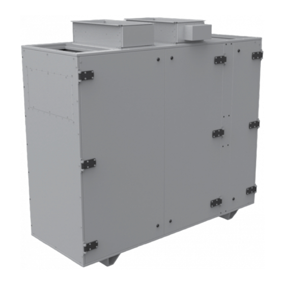
- Page 1 USER’S MANUAL Airvents CFV Air handling unit...
-
Page 2: Table Of Contents
Warranty card ....................................19 This user’s manual is a main operating document intended for technical, maintenance, and operating staff. The manual contains information about purpose, technical details, operating principle, design, and installation of the Airvents CFV unit and all its modifications. - Page 3 MANUFACTURER’S LABEL. ANY TAMPERING WITH THE INTERNAL CONNECTIONS IS PROHIBITED AND WILL VOID THE WARRANTY. INSTALLATION ONLY BY EXPERTS AND ONLY IN ACCORDANCE WITH LOCAL REQUIREMENTS AND NATIONAL ELECTRICAL CODE. DISCONNECT THE UNIT FROM POWER SUPPLY BEFORE ANY MAINTENANCE OPERATIONS! www.vents-us.com...
- Page 4 PROMINENT WARNING DEVICE, SUCH AS A TAG, TO THE SERVICE PANEL. FOR GENERAL VENTILATING USE ONLY. DO NOT USE TO EXHAUST HAZARDOUS OR EXPLOSIVE MATERIALS AND VAPORS. THE PRODUCT MUST BE DISPOSED SEPARATELY AT THE END OF ITS SERVICE LIFE. DO NOT DISPOSE THE UNIT AS UNSORTED DOMESTIC WASTE www.vents-us.com...
-
Page 5: Purpose
(toxic substances, dust, pathogenic germs). DELIVERY SET Name Number Unit 1 pc. User's manual 1 pc. Technical data sheet 1 pc. Automation wiring 1 pc. Control panel 1 pc. User's manual for automation 1 pc. Packing box 1 pc. www.vents-us.com... -
Page 6: Designation Key
Airvents CFV DESIGNATION KEY www.vents-us.com... -
Page 7: Technical Data
AV02 CFV 1500 71.7 61.0 76.8 29.5 AV02 CFV 2500 AV03 CFV 3500 81.5 70.9 86.6 35.0 AV07 CFV 5000 81.5 70.9 91.7 54.7 AV07 CFV 6000 The full technical data list is stated in the supplied technical data sheet. www.vents-us.com... -
Page 8: Unit Design And Operating Logic
Airvents CFV UNIT DESIGN AND OPERATING LOGIC UNIT DESIGN 1: drain pipe 2: water heater (only for the units with water heater) 3: electric heater (only for the units with electric heater) 4: supply fan 5: supply filter 6: extract fan... - Page 9 The unit design provides change of the air duct positioning. For this purpose the side walls are plugged. To change positioning of the air ducts use the plugs from the side walls for the front panel. Intake air Exhaust air Extract air Supply air www.vents-us.com...
-
Page 10: Installation And Set-Up
Airvents CFV INSTALLATION AND SET-UP The units are available in left- and right-sided modifications with the right or left service side. All the assembly units are accessible on the service side. Left-sided modification (service side view) Right-sided modification (service side view) - Page 11 Connect the drain pipe, U-trap and sewage system using metal, plastic or rubber connecting pipes. 1: drain pipe 2: connecting pipe 3: U-trap 4: sewage system min 3° Prior to starting operation make sure that water has unobstructed flow in the sewage system. Fill the U-trap with water before operation. www.vents-us.com...
- Page 12 Airvents CFV Connection of the water heater (only for the models with water heater) While connecting the water heater keep the straight air duct section length not less than 15 mm from the unit. Otherwise the maintenance panel cannot be opened!
-
Page 13: Connection To Power Mains
Dust deposits on the inner parts of the unit, especially in the electric heater, may lead to unpleasant odours. It is not a malfunction. Clean the unit to troubleshoot unpleasant odours. Open the service doors to access the filters. Remove the filter elements. www.vents-us.com... - Page 14 Airvents CFV To access the heat exchanger remove the holder 13 (see page 7). Loosen the screws (1) on the retaining clamps (2) using a hexagon wrench. Pull the heat exchanger out. www.vents-us.com...
-
Page 15: Storage And Transportation Regulations
The unit can be transported only in the working position. • Avoid sharp blows, scratches, or rough handling during loading and unloading. • Prior to the initial power-up after transportation at sub-zero temperatures, allow the unit to warm up at operation temperatures for at least 3-4 hours. www.vents-us.com... -
Page 16: Manufacturer's Warranty
Airvents CFV MANUFACTURER’S WARRANTY Production meets standard operating requirements in the USA and Canada. Vents US warrants to the original purchaser of the unit that it will be free from defects in materials or workmanship for a period of 24 months from the date of original purchase. The Vents US warrants to the original purchaser of the unit that the integrated control unit will be free from defects in materials and workmanship for a period of 24 months from the date of original purchase. -
Page 17: Certificate Of Acceptance
The unit has been installed in accordance with the provisions of all the applicable local and national construction, electrical and technical codes and standards. The unit operates normally as intended by the manufacturer. Signature: WARRANTY CARD Unit Type Air handling unit Model Serial Number Manufacture Date Purchase Date Warranty Period Seller Seller’s Stamp www.vents-us.com... - Page 18 Airvents CFV www.vents-us.com...
- Page 19 www.vents-us.com...
- Page 20 VUSA192-5EN-02...
Need help?
Do you have a question about the Airvents CFV and is the answer not in the manual?
Questions and answers