Table of Contents

Related Manuals for Farmi PROFI CH27 DMR

Summary of Contents for Farmi PROFI CH27 DMR
- Page 1 MANUAL FEED CHIPPER CH27 DMR OPERATION, MAINTENANCE AND SPARE PARTS MANUAL FROM MACHINE: 00065 TRANSLATION OF THE INSTRUCTION MANUAL PLEASE READ THE OPERATING AND MAINTENANCE INSTRUCTIONS BEFORE YOU OPERATE THE MACHINE. B-EN-051017-ER...
-
Page 3: Table Of Contents
CONNECTING THE WIRE HARNESS W150 VARAOSAT / W150 SPARE PARTS NO STRESS REVOLUTION CONTROL DEVICE INSTALLATION OF THE NO STRESS SENSOR SETUP GUIDE W150 FOR FARMI FOREST CHIPPER ALARMS INSTALLING HD 50 HYDRAULIC UNIT COUPLING HD 50 UNIT HYDRAULIC HOSES WITHOUT OIL COOLER... - Page 4 CH27 DMR CHIPPING ADJUSTMENT OF THE FEED SPEED STOPPING THE CHIPPER LOCATION AND USE OF SAFETY SWITCHES STORAGE INSTRUCTIONS MAINTENANCE MEASURES TO TAKE BEFORE MAINTENANCE ITEMS LUBRICATING THE BEARINGS LUBRICATING THE PTO SHAFT PERIODIC INSPECTIONS KNIFE MAINTENANCE SHARPENING CUTTING KNIVES ADJUSTING CHIP LENGTH ADJUSTING THE HORIZONTAL ANVIL REPLACING THE SPLINED SHAFT...
- Page 5 Name: Matti Berg Address: Ahmolantie 6, FIN-74510 IISALMI, Finland Commercial name: Farmi Machine denomination: Farmi wood chipper with attachable Farmi feed hopper Machine type: Wood chipper: FARMI CH27 Available feed hoppers for manual feed: Machine series number: Herewith, we declare that the machine brought into circulation conforms with the pertinent requirements of the Machinery Directive 2006/42/EC and the EMC Directive (directive relating to electromagnetic compatibility) 2004/108/EC.
-
Page 6: Introduction
CAUTION! PRODUCT WARRANTY Farmi provides a 12-months warranty on all Farmi products. Register on our home page (www.farmiforest.fi) under FeedBack (”Product Registration” form) within 30 days after the receipt of the product to get full product warranty and additional information on your product. If it is not possible for you to register via internet, please register as follows: Complete the registration form on the last pages of this manual and return it to us within 30 days after the receipt of the product. -
Page 7: General Description And Intended Use Of The Chipper
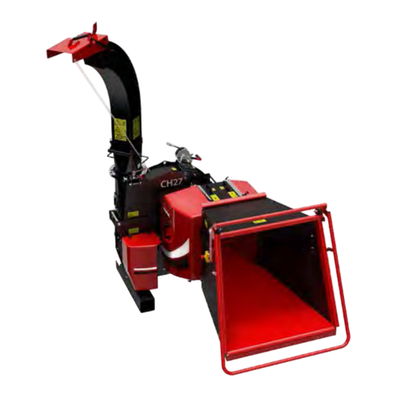
CH27 DMR GENERAL DESCRIPTION AND INTENDED USE OF THE CHIPPER FARMI CH27 is a disk chipper for tractor- mounted operation. As the chip size is adjustab- le, the chipper can be used e.g. for the producti- on of chips to be used for landscaping or for bio energy. -
Page 8: Description Of Worksites
CH27 DMR DESCRIPTION OF WORKSITES A worksite with a level and firm surface should be used when chipping. Clear any small brush and stones from the worksite. The material to be chipped should be as clean as possible - make every effort to keep soil or stones from entering the chipper. -
Page 9: Accessories
CH27 DMR CH27 + DMR MACHINE COMBINATION FOR MANUAL FEED WARNING! EXCLUSIVELY FOR MANUAL FEED! GRAB LOADER FEED PROHIBITED! ACCESSORIES 1. Independent hydraulic unit HD50 • Recommended for use if the tractor hydrau- lic output is above or below the CH27 chip- per oil requirement of approximately 45 l/ min. -
Page 10: General Safety Instructions
Written authorization must be requested from the manufacturer for any altera- These safety instructions are meant for the tions to the machine. owners of FARMI machine, as well as those who operate, service or repair it. CAUTION! The instructions help with: •... - Page 11 CH27 DMR 13. Before mounting and using the machine, OPERATION check the PTO drive shaft for correct condi- Many occupational acci- tion and attachment. dents take place in ab- 14. Never use a faulty or deficient machine. normal circumstances. 15. Using the tractor link arms to mount the top Therefore it is important link is prohibited.
- Page 12 CH27 DMR MAINTENANCE OILS AND LUBRICATION 1. The machine may only be serviced and 1. Always use the oil types recommended by repaired by professionals. the manufacturer. Other types of oil may 2. Electrical and hydraulic faults may only be cause faults or improper operation of the repaired by authorized professionals.
- Page 13 CH27 DMR 8. Do not attempt to carry out repairs that you are not fully familiar with. 9. Never carry out repairs of the hydraulic cir- cuit when the system is pressurized. When pressurized, the oil spray can penetrate the skin and cause mortal danger.
-
Page 14: General Safety Instructions For The Chipper
CH27 DMR GENERAL SAFETY INSTRUCTIONS FOR THE Noise from the chipper ex- CHIPPER ceeds 70 db in operation. Wear ear protection! CAUTION! DANGER! 1. People are not to ride on top of the chipper. 2. The chipper may not be used indoors. 3. -
Page 15: Technical Information
CH27 DMR TECHNICAL INFORMATION CH27DMR Type Disk chipper Output, m 5-25 Max. wood diameter, mm Feed chute size, mm 250 x 260 Chip length, mm 5-25 Power demand, kW 40-115 PTO speed, rpm 540-1000 Short discharge pipe reach, m Long discharge pipe reach, m Side transition pipe reach, m 2,85-3,5 Number of knives, pcs... -
Page 16: Main Components
CH27 DMR MAIN COMPONENTS 1. TOP FRAME 9. WINCH 2. BASE FRAME 10. FEEDER DEVICE 3. KNIFE DISC 11. FEEDING CHUTE 4. KNIFE 12. FEED CHUTE SUPPORT 5. HORIZONTAL ANVIL 13. PROTECTION SYSTEM 6. TWIG BREAKER 14. 3-POINT MOUNTING FRAME 7. -
Page 17: Dimensions
CH27 DMR DIMENSIONS CH27 DMR... - Page 18 CH27 DMR 200001545 DISCHARGE PIPE, SHORT 1268 HEIGHT WITH THE CHIPPER 27: 2,9 m 200001344 DISCHARGE PIPE, SIDE TRANSITION 2030 LIFTING POINT 2121 LIFTING POINT HEIGHT WITH THE CHIPPER 27: 2,7 - 3,2 m...
- Page 19 CH27 DMR 200002275 DISCHARGE PIPE, HIGH 1268 HEIGHT WITH THE CHIPPER 27: 3,9 m...
-
Page 20: Stickers And Plates
CH27 DMR STICKERS AND PLATES The following plates and labels must be correctly attached to the chipper. Missing safety plates / labels must be replaced immediately. - Page 21 CH27 DMR 1. Machine plate FARMI CH27 (200002361) 2. CAUTION! Please read the instruction manuals of the machine meticulously before you operate, maintain or repair the machine. During machine operation, please observe the operating and safety instructions. (40147020) 3. (40147000)
- Page 22 CH27 DMR 4. Wear personal protective equipment. (40142080). 5. Cutting hazard! (40147010) 6. Lifting point sticker (41014270) 7. SPEED sticker (40141160) Recommended speed range. The rated speed must not be exceeded. 8. MAXIMUM Hydraulic pressure 175 bar (41015580) 9. Sticker CH27 (200001868) 10.
- Page 23 CH27 DMR 11. FARMI Profi sticker (200002504) 12. Note! Stand on the left side of feeder. (41015690) 13. Crushing hazard! Cutting hazard! Do not climb into the feed hopper. (40147040) 14. Crushing hazard! Always keep a safe distance to rotating parts.
-
Page 24: Lifting
CH27 DMR LIFTING LIFTING THE DISCHARGE PIPE WITH THE WINCH The winch on the chipper’s upper housing is only intended for use in lifting and lowering the discharge CAUTION! pipe. CAUTION! Lifting points for each machine are marked with hook symbols. Exercise caution when using the winch. -
Page 25: Mounting Of The Discharge Pipe
CH27 DMR MOUNTING OF THE DISCHARGE PIPE If the chipper is equipped with an optional dis- charge pipe control device, the latter must be 1. Mount the lower part of the discharge pipe mounted on the chipper before the discharge pipe. -
Page 26: Adjusting The Discharge Pipe And Lid
CH27 DMR ADJUSTING THE DISCHARGE PIPE AND LID • Open the band tightening bolt. Turn the pipe in the desired direction. Tighten the bolt. • Adjust the lid by changing the chain length. Fig. 2. Direct the discharge pipe so that the thrown out chips do not pose a risk to the operator of the chipper or to or anyone else. -
Page 27: Coupling The 3-Point Mounting To The Chipper
CH27 DMR COUPLING THE 3-POINT MOUNTING TO THE CHIPPER A = M24X70, DIN933 B = M24, DIN126 C = M24, DIN985 Couple the 3-point mounting to the chipper as shown in the figure, using bolt A (6 pcs), washer B (12 pcs) and lock nut C (6 pcs). -
Page 28: Mounting The Feed Chute To The Feeder Device
CH27 DMR MOUNTING THE FEED CHUTE TO THE FEEDER DEVICE A = M12X35, DIN603 B = M12, DIN125 C = M12, DIN985 Mount the feed chute (DMR) from both sides to the feeder device using bolt A (8 pcs), washer C (8 pcs) and lock nut B (8 pcs). -
Page 29: Coupling The Feeder Device To The Chipper (Dmr)
CH27 DMR COUPLING THE FEEDER DEVICE TO THE CHIPPER (DMR) Mount the feeder device to the chipper as shown in figures A and B. The feeder device lugs fit between the chipper lugs. -
Page 30: Mounting The Feeder Device Support
CH27 DMR MOUNTING THE FEEDER DEVICE SUPPORT A = M12X35, DIN603 B = M12, DIN125 C = M12, DIN985 F = M16X50, DIN933 G = M16, DIN125 H = M16, DIN985 I = M12X100, DIN931 J = M12, DIN125 K = M12, DIN985 O = M24X120, DIN931 P = M24, DIN126 Q = M24, DIN985... -
Page 31: Shortening The Pto Shaft
CH27 DMR SHORTENING THE PTO SHAFT The use of too long a PTO shaft with a 3-point hitch could damage the chipper’s bearings or the tractor’s Measure distance A when the distance between PTO shaft. Both halves of the splined shafts is at its shortest. CAUTION! the PTO shaft must be shortened equally. -
Page 32: Connecting The Hydraulics Dmr
CH27 DMR CONNECTING THE HYDRAULICS DMR... - Page 33 CH27 DMR CONNECTING THE HYDRAULICS DMR 200002195 CH27 CHIPPER HYDRAULICS Part Order no Description Remarks 200002095 Valve 03520490 Hose assembly K1/2S, L=0.5 m + quick coupling 200002527 Hose assembly K1/2S, L=0.5 m + quick coupling, yellow 200002528 Hose assembly K1/2S, L=0.5 m + quick coupling, white 200002199 Hose assembly K1/4S, L=0.55 m + quick coupling, 1/4”...
-
Page 34: Connecting The Wire Harness
CH27 DMR CONNECTING THE WIRE HARNESS... -
Page 35: W150 Varaosat / W150 Spare Parts
CH27 DMR W150 VARAOSAT / W150 SPARE PARTS... -
Page 36: No Stress Revolution Control Device
CH27 DMR NO STRESS REVOLUTION CONTROL DEVICE INSTALLATION OF THE NO STRESS SENSOR The NO STRESS revolution control device stops 1. Turn off the tractor and uncouple the the feed unit when it detects a low cutting disk universal shaft. Open the upper housing. speed. -
Page 37: Setup Guide W150 For Farmi Forest Chipper
CH27 DMR SETUP GUIDE W150 FOR FARMI FOREST CHIPPER OVERVIEW The instrument monitors the chipper RPM and ‘No Stress’ function will engage and disengage the feed rollers at a programmable threshold. DISPLAY FUNCTIONS Chipper RPM Total hours Hours to service Press &... - Page 38 CH27 DMR MACHINE SETUP NO STRESS SPEED 2. When the chipper is rotating at the desired speed, press and hold SET for 5 seconds. For ‘LO’ the No Stress speed is currently set Keep the button pressed until the num- to 480 rpm, if this needs changing it can be ber flashes and the instrument beeps and programmed in 2 different ways:...
- Page 39 CH27 DMR Once the chipper speed has dropped below the no-stress speed, it must return to a certain RPM before the feed rolls are engaged again. This is expressed as a percentage of the No Stress speed. Currently set to 11% e.g if No Stress speed is 480 rpm, feed rolls will stop when chip- per speed is <480 rpm and will only start to ro- tate again when speed reaches 480 + 11% = 530...
- Page 40 CH27 DMR OPERATION When the speed is greater than the ‘No-Stress’ speed + resume percentage then operation of the feed rollers is allowed. Switch box operation is as follows: Turn to operate reverse. Display shows ‘rr’ when held. Turn to operate forward. Turn &...
- Page 41 CH27 DMR When the feed rollers forward is on it will only 4. OPERATION OF THE STOP BUTTON ON THE be turned off by any of the following: WIZARD Normal operation can be resumed by 1. NORMAL ‘NO STRESS’ OPERATION pressing and holding the ‘RESET’...
- Page 42 CH27 DMR...
-
Page 43: Alarms
CH27 DMR ALARMS HIGH CHIPPING SPEED SEr = Service interval reached The instrument will default to the chipping SAFE = Safety switch has been pressed speed channel (channel 2), the speed will flash STOP = Stop button has been pressed and the instrument will beep continuously. - Page 44 CH27 DMR STOP ALARM If during normal chipping operation the ‘STOP’ button is pressed then all the O/P’s will be dis- abled. This instrument will alarm and flash ‘StoP’ on channel 2. Normal operation can be resumed by pressing the holding the ‘RESET’ button for 5 seconds whilst on channel 2.
-
Page 45: Installing Hd 50 Hydraulic Unit
CH27 DMR INSTALLING HD 50 HYDRAULIC UNIT 1. Remove the tow triangle. 2. Remove the universal shaft shield A and shield brackets B and C. - Page 46 CH27 DMR 3. Mount the large pulley in the threads of the splined shaft with holes pointing outward. 3. Lift the HD unit between the legs of the chipper so that the bolt holes are aligned.
- Page 47 CH27 DMR 4. Mount the belt on the pulleys and align the pulleys using a level rod or ruler. Once this is done, tighten the securing bolts and nuts. Lastly, tighten the belts using the J-shaped bolts and nuts on the side of the HD unit.
-
Page 48: Coupling Hd 50 Unit Hydraulic Hoses Without Oil Cooler
CH27 DMR COUPLING HD 50 UNIT HYDRAULIC HOSES WITHOUT OIL COOLER 56526130 54921382 56533052 56534175 5. Disconnect the pressure hoses and return hoses from the tractor hydraulics. Couple the hydraulic unit hoses as shown in the Figure. 56534175 3/4”, 190, K3/4”S, L=1.2 m 56533052 V3/4”S L=0.5 m 54921382... -
Page 49: Mounting The Oil Cooler
CH27 DMR MOUNTING THE OIL COOLER 6. Fasten the oil cooler to the hydraulic unit as shown in the Figure. -
Page 50: Coupling The Hydraulic Hoses Of Hd 50 Unit And Oil Cooler
CH27 DMR COUPLING THE HYDRAULIC HOSES OF HD 50 UNIT AND OIL COOLER 56526130 54921382 56533052 56534134 56534084 7. Couple the hydraulic hoses as shown in the Figure. Finally, reinstall the tow triangle. 56534084 K3/4”S L=0.65 m 56534134 K3/4”S L=0.9 m 56533052 V3/4”S L=0.5 m 54921382... -
Page 51: Connecting The Oil Cooler To Tractor Battery
CH27 DMR CONNECTING THE OIL COOLER TO TRACTOR BATTERY BATTERY +12VDC FUSE Connect the oil cooler cables to the tractor battery as shown in the Figure. -
Page 52: Installation Of The Emk27 Electric Motor Mount (Accessory)
CH27 DMR INSTALLATION OF THE EMK27 ELECTRIC MOTOR MOUNT (accessory) Universal shaft Mount the chipper frame to concrete using M20 or Drill 4 holes in the chipper larger concrete anchors. feet for M24 x 70 screws. 4 pcs M16 x 50 hex screws in the chipper feet... - Page 53 CH27 DMR 2. Align the belt pulleys. Tighten the belts. Then, replace the belt guard. 1. Mount the SPB5 x 250 belt pulley to the motor and then mount the motor to the frame. 3. Connect the power supply.
- Page 54 CH27 DMR MOUNTING THE EMK27 ELECTRIC MOTOR TO CONCRETE EXPANSION JOINT 10 mm THICK FULL-ROUND BASE SLAB EXISTING SLAB (THICKNESS UNKNOWN) 1090 REINFORCEMENT TOP & BOTTOM - SL81 40 mm COVER ON ALL SIDES - SL82 60 mm COVER AT LEAST M20 CONCRETE ANCHORS CONCRETE N32 M16 H/D GR 8.8...
-
Page 55: Operating Instructions
CH27 DMR OPERATING INSTRUCTIONS STARTING THE CHIPPER MOUNTING OF THE CHIPPER AND 1. On the chipper display, select the right No Stress preset value according to the PTO PRE-OPERATION INSPECTIONS speed being used. The selection is made by pressing and holding the ”No Stress” but- 1. -
Page 56: Chipping
CH27 DMR CHIPPING During chipping, please observe the following safety instructions: DANGER! 1. Always read the operating and safety instructions of the used feed unit before operating the chipper. 2. Chipper with manual feed: Never work in front of the feed hopper. Stand on the left side of the feed hopper when feeding. -
Page 57: Adjustment Of The Feed Speed
CH27 DMR ADJUSTMENT OF THE FEED SPEED The feed speed must be set with the chipper running. Please observe the follo- wing safety instructions: DANGER! • Never stand in front of the feed hopper! Set the feed speed when standing to the left of the feed unit. -
Page 58: Stopping The Chipper
CH27 DMR LOCATION AND USE OF SAFETY SWITCHES STOPPING THE CHIPPER If necessary, the feed can be shut off using a Slow the tractor engine speed to idle before safety switch. The feeder device will stop imme- disengaging the PTO. This is especially impor- diately when the safety switch is pressed. -
Page 59: Storage Instructions
CH27 DMR STORAGE INSTRUCTIONS MAINTENANCE UNCOUPLING THE CHIPPER FROM THE TRAC- MEASURES TO TAKE BEFORE 1. For coupling or uncoupling the chipper, always turn off the tractor and apply the parking brake before entering the area bet- ween the chipper and tractor. WARNING! 2. -
Page 60: Maintenance Items
CH27 DMR MAINTENANCE ITEMS MAINTENANCE ITEM ACTION NOTES INTERVAL Chipper frame and Tighten pins and nuts Weekly All pins and nuts must be knife units tightened after the first opera- ting hour! For the torques, see the table. Check twig breaker At the time of Check the twig breaker and and additional knife... -
Page 61: Lubricating The Bearings
CH27 DMR LUBRICATING THE BEARINGS 1. The bearings are lubricated at the factory, and a similar lubricant should be used for subsequent lubrication (Shell Alvania Grease R 3. or Kendall L427). An excessive amount of grease causes overheating and impairs lubrication. 2. -
Page 62: Periodic Inspections
CH27 DMR PERIODIC INSPECTIONS Item Wrench span width, mm Torque, Nm Knife holder fastening screw tension Knife fastening screw tension Knife fastening screw tension Twig blade fastening screw tension (8 pcs, 4 pcs on each side of the chipper) Tightening the lower nuts on the twig and cross breaker Tightening the upper nuts on the twig and cross breaker... -
Page 63: Knife Maintenance
CH27 DMR KNIFE MAINTENANCE A = M20x280 DIN 931 B = M20 DIN 985 Remove bolt A and nut B. Open the upper housing toward the discharge pipe. Lock the knife disk during maintenance. Turn the knife disk until the hole in the disk is aligned with locking pin D. Re- move locking pin circlip C and push the pin into the hole in the disk. -
Page 64: Sharpening Cutting Knives
CH27 DMR SHARPENING CUTTING KNIVES Sharpen all knives equally. This ensures disk balance. Avoid heating the knife during sharpening. CAUTION! The knives need sharpening when: 0,2 mm • The self-feeding of wood has decreased • The power demand has increased •... -
Page 65: Adjusting Chip Length
CH27 DMR ADJUSTING CHIP LENGTH 5-25 mm 4. Adjust the perpendicular distance of both 1. Lock the knife disk with lock pin A. ends of knife C from the edge of the knife disk. 2. Move the anvils to their outermost position If necessary, tap the knife holder with a wooden so that the knives do not strike each other after or rubber mallet. -
Page 66: Adjusting The Horizontal Anvil
CH27 DMR 5. Tighten the knife holder nuts and make a ve- rifying measurement. Measure both ends of the knife from the top edge of the base frame. Enter the distance in the memory. 1. Loosen the horizontal anvil screws. 6. -
Page 67: Replacing The Splined Shaft
CH27 DMR REPLACING THE SPLINED SHAFT DISPOSAL OF THE MACHINE 1. Remove the upper chamber. When the operating life for the machine has 2. Remove the bearings. Welding damages the come to an end it must be disposed by using bearings. -
Page 68: Troubleshooting
CH27 DMR TROUBLESHOOTING ISSUE phase 1 phase 2 ELECTRICAL Feed rollers not rotating at SAFE appears on the display. The safety stop button or sa- all. fety limit switch is activated -> pull out the safety stop but- ton or release the safety limit switch. -
Page 69: 200002095 Valve
CH27 DMR 200002095 VALVE Part Order no Description Remarks Valve block 200001322 Flow dividing valve 56057243 Directional valve 200001326 Flow control valve feed roller speed 200001327 Flow control valve 200003766 Cartridge valve 200003884 Solenoid coil 200003794 Pressure relief valve... -
Page 70: 200001499 Chipper Ch 27D
CH27 DMR 200001499 CHIPPER CH 27D... - Page 71 CH27 DMR 200001499 CHIPPER CH 27 Part Order no Description Remarks 200001277 Base frame 200001276 Top frame 200001516 Twig blade 200000949 Knife disc complete 200000941 Knife disc 200000507 Knife holder 200000508 Support plate 200000728 Blade 52117215 Lock nut ST10.9ZN, M20X1,5, DIN985 52063617 Hex screw ST10.9 BLACK, M12X40, DIN933...
- Page 72 CH27 DMR 200001499 CHIPPER CH 27 Part Order no Description Remarks 52117082 Lock nut ST8.8ZN, M8, DIN985 52060183 Hex screw ST8.8ZN, M8X30, DIN933 52832045 Drive rivet FE, 4,8X19 03291143 Chain CH160, D2-250MM 52842143 Hair pin cotter ZN, 5X10⁵, DIN11024 52062031 Hex screw ST8.8ZN, M12X40, DIN933 200000307 Lock screw...
-
Page 73: 200002207 3-Point Mounting, Fastener
CH27 DMR 200002207 3-POINT MOUNTING, FASTENER Part Order no Description Remarks 200001535 Fastener 52832045 Drive rivet 52842150 Lynch pin ZN, 10X45, DIN11023 03291143 Chain 200002082 Lug 52062031 Hex screw ST8.8ZN, M12X40, DIN933 52200052 Washer ST5.8ZN, M12, DIN125 200002093 Hook 52117124 Lock nut ST8.8ZN, M12, DIN985 43482290... -
Page 74: 200001545 Short Discharge Pipe
CH27 DMR 200001545 SHORT DISCHARGE PIPE... - Page 75 CH27 DMR 200001545 SHORT DISCHARGE PIPE Part Order no Description Remarks 52062437 Hex screw ST8.8ZN, M20X260, DIN931 52117207 Lock nut ST8.8ZN, M20, DIN985 52062840 Eye screw ST8.8ZN, M12X120, DIN444 52200466 Washer ZN, M12, DIN440 52117900 Wing nut ST4.6ZN, M12, DIN315 52200052 Washer ST5.8ZN, M12, DIN125...
-
Page 76: 200002275 High Discarge Pipe
CH27 DMR 200002275 HIGH DISCARGE PIPE... - Page 77 CH27 DMR 200002275 HIGH DISCARGE PIPE Part Order no Description Remarks 52062437 Hex screw ST8.8ZN, M20X260, DIN931 52117207 Lock nut ST8.8ZN, M20, DIN985 52062840 Eye screw ST8.8ZN, M12X120, DIN444 52200466 Washer ZN, M12, DIN440 52117900 Wing nut ST4.6ZN, M12, DIN315 52200052 Washer ST5.8ZN, M12, DIN125...
-
Page 78: 200001344 Discharge Pipe, Side Transition
CH27 DMR 200001344 DISCHARGE PIPE, SIDE TRANSITION 3.3 3.2 3.10 3.13 3.12 3.14 3.15 3.11... - Page 79 CH27 DMR 200001344 DISCHARGE PIPE, SIDE TRANSITION Part Order no Description Remarks 200001340 Lower part 200002494 Intermediate tube complet 200001343 Intermediate tube 52062840 Eye screw ST8.8ZN, M12X120, DIN444 52200466 Washer ZN, M12, DIN440 52117900 Wing nut ST4.6ZN, M12, DIN315 52062627 Hex screw ST8.8ZN, M12X50, DIN931 52200052...
-
Page 80: 200002150 Vizor Steering , Manual
CH27 DMR 200002150 VIZOR STEERING , MANUAL Part Order no Description Remarks 84614106 Extension spring DU38 DL4,25 L250 54826227 Knot chain 52200037 Washer ST5.8ZN, M8, DIN126 52117082 Lock nut ST8.8ZN, M8, DIN985... -
Page 81: 200002147 Vizor Steering, Hydraulic
CH27 DMR 200002147 VIZOR STEERING, HYDRAULIC Part Order no Description Remarks 56097793 Hydraulic cylinder 32/20-150, 200 bar 43487470 Fastening plate 43487480 Fastening plate 200002144 Fastener for cylinder 200002145 Fastener for cylinder 52060282 Hex screw ST8.8ZN, M10X70, DIN931 52060266 Hex screw ST8.8ZN, M10X50, DIN931 52200045 Washer... -
Page 82: 200002176 Discharge Chute Steering, Hydraulic
CH27 DMR 200002176 DISCHARGE CHUTE STEERING, HYDRAULIC... - Page 83 CH27 DMR 200002176 DISCHARGE CHUTE STEERING, HYDRAULIC Part Order no Description Remarks 200001478 Tightener flange 56002020 Hydraulic motor 250CC, MR 250 SH D 43800820 Washer 43801800 Groove shaft 52200235 Flat washer ST5.8ZN, M8, DIN9021 52060175 Hex screw ST8.8ZN, M8X25, DIN933 52432226 Double fitting R1/4-1/2...
-
Page 84: 200002183 Discharge Chute Steering, Mechanical
CH27 DMR 200002183 DISCHARGE CHUTE STEERING, MECHANICAL Part Order no Description Remarks 200001478 Tightener flange 200001479 Intermediate flange 43295070 Tightener 52200052 Washer ST5.8ZN, M12, DIN125 52063047 Hex screw ST8.8ZN, M12X110, DIN931 52117124 Lock nut ST8.8ZN, M12, DIN985 54924890 Retainer lever 52062041 Hex screw ST8.8ZN, M12X50, DIN933... -
Page 85: 200002273 Feeder Device 27 Dmr, Complete
CH27 DMR 200002273 FEEDER DEVICE 27 DMR, COMPLETE Part Order no Description Remarks 200002260 Feed chute 200002175 Feeder device 200002240 Support 200001388 Lock screw ST8.8ZN, M12X35, DIN603 52200052 Washer ST5.8ZN, M12, DIN125 52117124 Lock nut ST8.8ZN, M12, DIN985... -
Page 86: 200001502 Feeder Device
CH27 DMR 200001502 FEEDER DEVICE... - Page 87 CH27 DMR 200001502 FEEDER DEVICE Part Order no Description Remarks 200001484 Frame 200001503 Feed roller 200001501 Swing 200001500 Feed roller 200001490 Swing frame 56002033 Hydraulic motor MR 400 3.3.1 58217640 Seal kit 52200466 Washer ZN, M12, DIN440 52214277 Lock washer M14, NORD-LOCK, DIN25201 52062015 Hex screw...
-
Page 88: 200002173 Protection System Hf27
CH27 DMR 200002173 PROTECTION SYSTEM HF27... - Page 89 CH27 DMR 200002173 PROTECTION SYSTEM HF27 Part Order no Description Remarks 200002125 Fastener 200002124 Fastening plate MEDIUM 200002129 Fastening plate LONG 200002112 Holder RUBBER, SMALL, 2 PCS. 200002143 Lock screw ST4.6ZN, M6X20, DIN603 52200342 Washer ZN, M6, DIN440 52117066 Lock nut ST8.8ZN, M6, DIN985 52832045 Drive rivet...
-
Page 90: 200002260 Feed Chute Dm
CH27 DMR 200002260 FEED CHUTE DM... - Page 91 CH27 DMR 200002260 FEED CHUTE DM Part Order no Description Remarks 200001564 Side plate oikea 200001565 Side plate vasen 200001599 Deck plating 200001603 Top strengthener 200002293 Pipe holder 200002692 Safety bar 200001626 Vibration damper 200001631 Base plate 200001630 Support plate 52021230 Lock screw ST8.8ZN, M8X20, DIN603...
-
Page 92: 200002584 Hydraulic Unit Hd50 (Accessory)
CH27 DMR 200002584 HYDRAULIC UNIT HD50 (accessory) 48.1 48.3 48.5 48.2 48.4 48.4 48.5 50 51 48.2 48.3... - Page 93 CH27 DMR 200002584 HYDRAULIC UNIT HD50 (accessory) Part Order no Description Remarks 200001081 Oil tank 200002786 Support bearing 200002569 Return pipe 200002413 Fastener 200002787 Belt pulley 43550810 Tightener 52211059 Spring washer ZN, M12, DIN127 52200086 Washer ST5.8ZN, M20, DIN126 52117207 Lock nut ST8.8ZN, M20, DIN985 52063914...
- Page 94 CH27 DMR 200002584 HYDRAULIC UNIT HD50 (accessory) Part Order no Description Remarks 52110079 Hex nut ST8.8ZN, M16, DIN934 52214285 Lock washer ZN, M16, DIN25201 Belt pulley 200003762 Angle coupling 1/8"-1/8", 60 bar 200003758 Shelter 48.1 200003749 Shelter plate 48.2 52060183 Hex screw ST8.8ZN, M8X30, DIN933 48.3...
- Page 95 CH27 DMR...
-
Page 96: 200002586 Oil Cooler (Accessory)
CH27 DMR 200002586 OIL COOLER (accessory) Part Order no Description Remarks 200002421 Fastener 54945990 Oil cooler 52200045 Washer ST5.8ZN, M10, DIN125 52060233 Hex screw ST8.8ZN, M10X30, DIN933 52117108 Lock nut ST8.8ZN, M10, DIN985 52200342 Washer ZN, M6, DIN440 52060456 Hex screw ST8.8ZN, M6X20, DIN933 33596100 Electrics... -
Page 97: 200002373 Cross Breaker (Accessory)
CH27 DMR 200002373 CROSS BREAKER (accessory) -
Page 98: 200002589 Emk27 Stationary Chipper Platform (Accessory)
CH27 DMR 200002589 EMK27 STATIONARY CHIPPER PLATFORM (accessory) 36 35 33 34 45 46 19 18 18... - Page 99 Hex screw ST8.8ZN, M12X35, DIN933 52200045 Washer ST5.8ZN, M10, DIN125 52117249 Lock nut ST8.8ZN, M24, DIN985 52200102 Washer ST5.8ZN, M24, DIN126 52200078 Washer ST5.8ZN, M16, DIN125 52062122 Hex screw ST8.8ZN, M16X50, DIN933 200002504 Farmi profi sticker 200002464 Cutting hazard sticker...
- Page 100 CH27 DMR 200002589 EMK27 STATIONARY CHIPPER PLATFORM (accessory) Part Order no Description Remarks 41014270 Lifting point sticker 52060225 Hex screw ST8.8ZN, M10X25, DIN933 52200474 Washer ZN, M10, DIN440 52062451 Hex screw ST10.9ZN, M24x220, DIN931 200003142 Auxiliary frame 200002835 Axle key 12X20X120 mm 53220281 Belt pulley...
- Page 101 Send faulty parts, carriage paid, to the manufacturer for inspection. Repairs will be con- ducted by Farmi Forest Oy or an authorized expert. The warranty is valid only if the bottom part of this page is filled in and returned to the manufacturer within 30 days of receipt of the product.
-
Page 102: Product Registration Form
PRODUCT REGISTRATION FORM Date of delivery:_____/_____ 20_____ Dealer: Dealer’s address: Dealer’s tel: Product and type: Serial number: Return to the manufacturer Date of delivery:_____/_____ 20_____ Dealer: Dealer’s address: Dealer’s tel: Customer: Customer’s address: Customer’s tel: E-mail: Product and type: Serial number:... - Page 103 Farmi Forest representatives: Western Europe Austria Belgium & Luxemburg Esch-Technik Maschinenhandel G.m.b.H. DEOM S.A. Klagenfurter Str. 129 A-9300 Rue de Monty, 177 ST. VEIT/GLAN B-6890 LIBIN Tel. +43 4212 2960-0 Tel. +32 61 656 025 / 655 248 office@esch-technik.at contact@deom.be...
- Page 104 Farmi Forest Corporation UK Unit 5 Wheler Road Seven Stars Industrial Estate Coventry CV3 4LJ, UK Tel. +44 (0)24 7746 1976 greg.worley@farmiforest.fi Farmi Forest representatives: Eastern Europe Belarus Estonia TIGER, Joint Stock Company Oü Melit AP 1st Twerdy lane, 7 - 17 Ümera 60-8 13816...
- Page 105 Farmi Forest representatives: North and South America Argentina Canada, Québec, Ontario Inderfor S.A. La Coop fédérée Pasco 1732 - 10º "A" 2000 Rosario 9001, Boul. de l’Acadie SANTA FE MONTRÉAL, QUÉBEC H4N 3H7 P. +54 (0)341 679 25 66 Tel. 819-379-8555 info@inderfor.com...
- Page 106 Smart Choices – Since 1962.
Need help?
Do you have a question about the PROFI CH27 DMR and is the answer not in the manual?
Questions and answers