Table of Contents
Advertisement
Quick Links
Advertisement
Table of Contents

Related Manuals for UNINEX KOOLZONE SAC-3000


Summary of Contents for UNINEX KOOLZONE SAC-3000
-
Page 2: Table Of Contents
Contents 1. Safety Marks …………………………………………… 1. 2 Page 2. Technical Data …………………………………………… 3 Page 3. Accessories 3 Page …………………………………………… 4. Parts Of The Machine 4 Page ………………………………… 5. Installation …………………………………………… 4.5 Page 6. Operation Instructions …………………………………… 5Page 7. Water Tank …………………………………………………... -
Page 3: Safety Marks
1. Safety Marks The identification of marks. Before operating, please read this instruction carefully. It may cause personal casualty and fire disaster or other property loss. Danger If neglecting of this mark and operating with wrong way. It may cause personal casualty and fire disaster or other property loss. Warning If neglecting of this mark and operating with wrong way. - Page 4 For your safety, Please follow instruction Please install the reliable earthing wire with leakage protector. Please operate the machine in the temperature range of 25°C~45°C, otherwise it may cause the accident. When operating, do not move the air conditioner and should check the castors’ brake is locked. If the machine is abnormal in operating period (such as stopping, noise, unusual shock and abnormal smell), please stop the machine immediately.
-
Page 5: Technical Data
2. Technical Data Power Single Phase 115V Frequency 60Hz Cooling Capacity 10236BTU Load Current High : 10.8A Low : 10.4A Consumption Power High : 1210W Low : 1170W Compressor Sealed rotary type Water Storage Capacity Refrigerant R410A Refrigerant(Rated charge) 800g Operating Temperature limit Size 18.5”×17.7”×37.4”... -
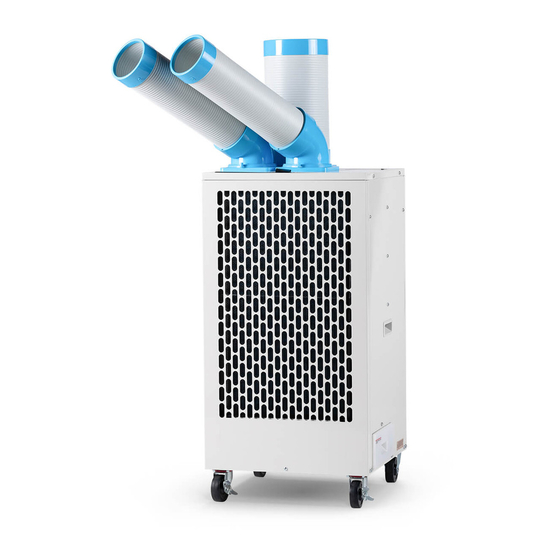
Page 6: Parts Of The Machine
4. Parts Of The Machine Cooling duct Heat duct Curved duct caster Water tank:5L Power wire 5. Installation Installation of the curved duct: Please make the convex part of the curved duct point to the concavo part of the bending base and insert it, then turn the duct in counterclockwise to lock. -
Page 7: Operation Instructions
Installation of the heat duct and socket: The heat duct socket uses 4 ST4×12 bolts to fix on the heat vent. When heat duct insertion heat duct socket, please note reliably. Heat duct Heat duct Heat vent Power supply connection socket Please use exclusive power supply When you have to use an extension wire, please be sure to use it... -
Page 8: Water Tank
7. Water Tank The condensate water will flow into water tank. The capacity of the tank is 5L. The water tank may take out directly from the machine. Extraction Note:Empty the water immediately when the water get to the red line. The machine does not have warning device. Red water line Please check the puantity of the water periodically. -
Page 9: Breakdown & Solve-Method
10. Breakdown & Solve-Method Fault state Cause Countermeasure The power plug has been loosed Insert the plug into wall socket well Not work Fuse was broken Ask the purchase agent for help Condenser’s surface is dirty and blocked Clean the condensor’s surface and vantilate or cool for the condensor Heat exhaust fan was breakdown Change the heat exhaust fan...