Advertisement
Quick Links
Advertisement

Related Manuals for Huazheng HZ-4000T2


Summary of Contents for Huazheng HZ-4000T2
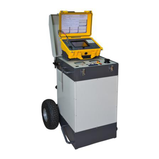
- Page 1 HZ-4000T2 Cable fault location system Operation Manual...
- Page 2 Please read the instructions carefully before using !!! ★ Operator must possess professional operation qualifications for high-voltage equipment ★ Strictly follow the national high-voltage equipment operating specifications ★ This instrument has a high-voltage characteristics, please pay attention to personal and equipment safety ★...
- Page 3 HZ-4000T2 Cable Fault Location System Introduction I. Introduction 1 It is a one body trolley structure, easy handling at site. 2 You can do site test without complex wiring, because all test modes and switching voltage levels are automatically switched by weak control internal high-voltage switches.
- Page 4 III. Technical Indicators 1 Test methods: Arc reflection method, current sampling, and DC output. 2 Types of sampling signals: Arc reflection method, current sampling, and low-voltage pulse. 3 DC voltage output: 0 ~ 32kV Negative Maximum output current: 76mA 0 ~ 16kV Negative Maximum output current: 152mA 4 Impact capacitor: 0 ~ 32kV 3μF Maximum output energy: 1536 joules...
- Page 5 HZ-4000T2 Cable Fault Location System Operation Guide I. External wiring 1 Perform test wiring as figure below: From left to right: 输入:Input 电缆故障定位系统:Cable Fault Location System 高压输出电缆: High-voltage output cable 保护地: Ground of protection 红夹子: Red clip 黑夹子: Black clip 系统地:...
- Page 6 II. Panel Figure In the drawing: 1. total switch 2. Adjusting the ignition time 3. Selecting test voltage 4. Selecting Test Mode 5. Start, ignition, stop key 6. Regulator knob 7. Output voltage indicator 8. Output current indicator...
-
Page 7: Operation Steps
9. Signal terminals III. Operation Steps 1. Correctly connect "Cable Fault Location System" and ground, faulty cable, AC 220V power line according to the external wiring diagram. It can also be connected via extension cable drum if equipped with one. 2. - Page 8 captures the current signal waveform reflected back and forth in the cable when impact. C. Location: Cable fault pinpoint use. D. DC output: It can output DC high-voltage to test cable. 5. Confirm that regulator knob is at zero and stop key is in non-locked state. Press the start key to start the instrument, and you can hear "plump"...
- Page 9 4. Do not allow the instrument stopped using more than 20 minutes. Turn off the power switch if you do not use it in a long-term. V. HZ-4000T2 Cable Fault Location System Physical List 1 HZ-4000T2 cable fault location system host...
-
Page 10: Main Features
HZ-400T2 Cable Fault Tester Introduction HZ-4000T2 cable fault tester is a new type power cable test equipment designed by our company based on the current low level of China's electric power system management, lagging of test methods. The instrument uses advanced microcomputer... -
Page 11: Technical Indicators
● Sample frequency: 30M, 60M, 120M multiple sampling frequency, higher test accuracy. ● Test distance: up to 165Km. ● Test Pulse: 0.2 ~ 9.9μs, adjustable. ● Error: Rough measurement relative error: less than ± 0.25%; Rough measurement absolute error: below 2 km cable length is less than one meter;... - Page 12 ● Small size, light weight, imported waterproof chassis, adapt to all kinds of harsh environment. ● Equipped with enhanced hardware waveform processing circuit compared with DMS-3500. HZ-4000T2 Cable Fault Tester Operation I. Panel Structure Introduction Panel layout schematic diagram as above, functions as following: ① Q output terminal ②...
-
Page 13: External Wiring
⑥ Waveform amplitude adjustment knob when sampling ⑦ Printer II. External Wiring 1. Wiring of low-voltage pulse method: The dedicated signal cable: Connect "Q output terminal" and "Q input terminal" on one side; Connect the red clip with cable core wire, and the black clip with cable shield ground or another phase on the other side. - Page 14 III. Main Display Interface Introduction Right: 采样方式:Sampling mode 采样频率: Sampling frequency 电波速度:Electrical wave 滤波方式: Filter mode 移动选择 Moves selection Bottom: 设置:Settings 起点: Start Point 采样: Sampling 工作电压:Working voltage The main display interface is shown, including various parameters and sampling waveform, each part as follows: ①...
- Page 15 ④ Compression ratio of main display area K2. ⑤ Distance from start point to fault point. ⑥ Green cursor of main waveform represents starting point, and white represents end point, and between green ~ white is the length of the cable. ⑦...
- Page 16 which means being charged for more than three hours when the power switch is off. ★ Ensure that the battery is fully charged every three months, and so ensure the battery life. ★ Screen will go into protection mode if there are four minutes without any operation when it’s AC power supply, and click anywhere on the screen to exit this protection.
- Page 17 base Sampling voltage / current sampling test method: Connect "input" signal base 2. Go to the first screen, press touch screen to enter "Select the length range of the cable under test", and you should select item greater than the total length of the cable under test.
- Page 18 be in "cursor" status, which is valid), and re-sampling takes effect. ③ If you think the amplitude of the overall waveform is inappropriate, you can adjust "Amplitude Adjustment" knob to adjust, and re-sampling takes effect. ④ If you want to compress or expand on left and right side to waveform on the lower window, press "+"...
- Page 19 VI. Usage of Each Function Menu, Main Menu on the Main Interface and Settings 1. Function of the Lower Row Keys * "Setting" button: Turn on the setting function. Each function will be set in a new opened menu. * "Starting Point" key: White cursor point in the waveform will be the starting point for calculating the cable length.
- Page 20 * "Sampling" Key: To start sampling, if you want to stop sampling, touch anywhere on the screen to end it. 2. Usage for Each Function Key "Settings" key is used to open a new menu, to set various parameters and the desired operation, or to enter corresponding interface when you need to adjust parameters or process waveform.
- Page 21 Bottom: 设置:Settings 起点: Start Point 采样: Sampling 工作电压:Working voltage Sub-menu of "Settings" menu will appear on the left of the screen, which are "Basic Parameters", "Pulse Settings", "Speed Settings", "Cable Speed", "Waveform Processing", "Time Setting" and "Exit", then press different keys respectively to enter sub-menu.
- Page 22 Basic Parameter Setting Interface Left: 基本参数:"Basic Parameters" 脉冲设置:"Pulse Settings" 速度设置:"Speed Settings" 电缆测速: "Cable Speed" 波形处理: "Waveform Processing" 时间设置: "Time Setting" 返回:"Exit" Middle: 采样主频:Sampling main frequency 全貌比例:Ratio of the whole picture 通讯速率:Communicating speed 返回:exit 确认:OK Right: 采样方式:Sampling mode 采样频率: Sampling frequency 电波速度:Electrical wave 滤波方式: Filter mode 移动选择...
- Page 23 transmission of multiple pulses, typically 50 microseconds to 200 microseconds and a maximum of 255 microseconds. It can be appropriately modified depending on the cable length. "Interval" refers to time interval between multiple pulses of an integer multiple of 10 microseconds, typically set to 2-5. The longer the cable length is, the larger this value is.
- Page 24 电波速度:Electrical wave 滤波方式: Filter mode 移动选择 Moves selection Bottom: 设置:Settings 起点: Start Point 采样: Sampling 工作电压:Working voltage "Speed Settings": Press "Speed Settings" key to enter sub-menu, and you can set different speed of cable. There are four different cable speed keys already, so you can directly click to select.
- Page 25 Middle: 油浸纸:Oil - immersed Paper 不滴流:Not trickle 交联乙烯:Crosslinked ethylene 聚氯乙烯:Polyvinyl chloride 速度设置:Speed settings 返回:exit 确认:OK Right: 采样方式:Sampling mode 采样频率: Sampling frequency 电波速度:Electrical wave 滤波方式: Filter mode 移动选择 Moves selection Bottom: 设置:Settings 起点: Start Point 采样: Sampling 工作电压:Working voltage "Cable Speed": Press "Cable Speed "key to enter sub-menu to measure cable speed. The premise is that you’ve already got electric wave in “Sampling”...
- Page 26 Cable Speed Settings Interface Left: 基本参数:"Basic Parameters" 脉冲设置:"Pulse Settings" 速度设置:"Speed Settings" 电缆测速: "Cable Speed" 波形处理: "Waveform Processing" 时间设置: "Time Setting" 返回:"Exit" Middle: 电缆距离:Cable distance 对应速度:Corresponding speed 返回:exit 确认:OK Right: 采样方式:Sampling mode 采样频率: Sampling frequency 电波速度:Electrical wave 滤波方式: Filter mode 移动选择 Moves selection Bottom: 设置:Settings 起点: Start Point 采样: Sampling...
- Page 27 performed. "Waveform Recall": Press "Waveform Recall" to bring up the previously stored waveform. Press up and down arrow keys in the lower row to select waveform in 60. Waveform is saved by sampling time, so select the waveform you want according to time displayed, and press "OK"...
- Page 28 波形打印:"Waveform Print" 返回:exit 确认:OK Right: 采样方式:Sampling mode 采样频率: Sampling frequency 电波速度:Electrical wave 滤波方式: Filter mode 移动选择 Moves selection Bottom: 设置:Settings 起点: Start Point 采样: Sampling 工作电压:Working voltage "Waveform Comparison": While main interface displays a waveform, you can call up another waveform for comparison, and this is the time when you use "Waveform Comparison"...
- Page 29 "Waveform Comparison" Interface Left: 基本参数:"Basic Parameters" 脉冲设置:"Pulse Settings" 速度设置:"Speed Settings" 电缆测速: "Cable Speed" 波形处理: "Waveform Processing" 时间设置: "Time Setting" 返回:"Exit" Middle: 波形调出:"Waveform Recall" 波形对比:"Waveform Comparison" 波形存储:"Waveform Storage" 波形删除:"Waveform Delete" 波形打印:"Waveform Print" 返回:exit 确认:OK Right: 采样方式:Sampling mode 采样频率: Sampling frequency 电波速度:Electrical wave 滤波方式: Filter mode 移动选择...
- Page 30 "Wave Delete" Interface Left: 基本参数:"Basic Parameters" 脉冲设置:"Pulse Settings" 速度设置:"Speed Settings" 电缆测速: "Cable Speed" 波形处理: "Waveform Processing" 时间设置: "Time Setting" 返回:"Exit" Middle: 波形调出:"Waveform Recall" 波形对比:"Waveform Comparison" 波形存储:"Waveform Storage" 波形删除:"Waveform Delete" 波形打印:"Waveform Print" 返回:exit 确认:OK Right: 采样方式:Sampling mode 采样频率: Sampling frequency 电波速度:Electrical wave 滤波方式: Filter mode 移动选择...
- Page 31 "Waveform Print": To print the waveform diagram displayed on the main interface, press "Print" key. "Time Setting": The instrument has a separate internal clock circuit. In order to correct the time to go, you can enter this interface to set date and time. Respectively press "year, month, day, hour, second"...
- Page 32 Right: 采样方式:Sampling mode 采样频率: Sampling frequency 电波速度:Electrical wave 滤波方式: Filter mode 移动选择 Moves selection Bottom: 设置:Settings 起点: Start Point 采样: Sampling 工作电压:Working voltage When all the settings are completed, observe the right of the display screen, and you can see if a variety of parameters are correct. 3.
- Page 33 4. Waveform Introduction in Various Sampling Methods The following figure shows the whole long-distance waveform for low-voltage pulse cable, or distance waveform of cable disconnection fault:...
- Page 34 Left: from top to bottom: 对 应 主 波 形 区 两 条 竖 游 标 : Corresponding to two vertical cursors of the main waveform area 全貌波形区: The whole picture of waveform area 低压脉冲测试方式波形: Low-voltage pulse test mode waveform 全貌波形压缩率:Compression ratio of the whole picture of waveform 主波形压缩率:Compression ratio of the main waveform 故障距离:Fault distance...
- Page 35 Left: from top to bottom: 对 应 主 波 形 区 两 条 竖 游 标 : Corresponding to two vertical cursors of the main waveform area 全貌波形区: The whole picture of waveform area 低压脉冲测试方式波形: Low-voltage pulse test mode waveform 全貌波形压缩率:Compression ratio of the whole picture of waveform 主波形压缩率:Compression ratio of the main waveform 故障距离:Fault distance...
- Page 36 移动选择 Moves selection Bottom: 设置:Settings 起点: Start Point 采样: Sampling 打印:Print The following figure shows a total length of low voltage pulse, short-circuit waveform comparison: Left: from top to bottom: 对 应 主 波 形 区 两 条 竖 游 标 : Corresponding to two vertical cursors of the main waveform area 全貌波形区: The whole picture of waveform area 低...
- Page 37 短路、低阻反射波形:Short circuit, low resistance reflected waveform 短路故障距离: Short-circuit fault distance 主波形区:Main waveform area 仪器发射的脉冲:Pulse launched by instrument 全长距离:Whole distance 全长反射波形:Whole distance reflected waveform Right: 采样方式:Sampling mode 采样频率: Sampling frequency 电波速度:Electrical wave 滤波方式: Filter mode 移动选择 Moves selection Bottom: 设置:Settings 起点: Start Point 采样: Sampling 打印:Print The following figure shows the voltage sampling waveform of high-voltage...
- Page 38 对 应 主 波 形 区 两 条 竖 游 标 : Corresponding to two vertical cursors of the main waveform area 全貌波形区: The whole picture of waveform area 整体压缩波形有震荡趋势,说明故障点意见击穿:Overall compression waveform has a shake trend, indicating that fault point has breakdown 电压取样测试方式波形: Voltage sampling test mode waveform 全貌波形压缩率:Compression ratio of the whole picture of waveform 主波形压缩率:Compression ratio of the main waveform...
- Page 39 Left: from top to bottom: 对 应 主 波 形 区 两 条 竖 游 标 : Corresponding to two vertical cursors of the main waveform area 全貌波形区: The whole picture of waveform area 电流取样测试方式波形: Current sampling test mode waveform 全貌波形压缩率:Compression ratio of the whole picture of waveform 主波形压缩率:Compression ratio of the main waveform 故障距离:Fault distance...
- Page 40 故障点波形二次反射:Waveform second reflection on point of fault Right: 采样方式:Sampling mode 采样频率: Sampling frequency 电波速度:Electrical wave 滤波方式: Filter mode 移动选择 Moves selection Bottom: 设置:Settings 起点: Start Point 采样: Sampling 打印:Print The following figure shows the sampling waveform of high-voltage multi-pulse(stable arc): Left: from top to bottom: 对...
- Page 41 全貌波形压缩率:Compression ratio of the whole picture of waveform 主波形压缩率:Compression ratio of the main waveform 故障距离:Fault distance 脉宽:Width 故障距离: Fault distance 电缆全长:Whole distance of cable 主波形区:Main waveform area Right: 采样方式:Sampling mode 采样频率: Sampling frequency 电波速度:Electrical wave 滤波方式: Filter mode 移动选择 Moves selection Bottom: 设置:Settings 起点: Start Point 采样: Sampling...
- Page 42 HZ-B Cable Fault Location Instrument I. Introduction HZ-B cable fault location instrument is an important instrument during searching for cable fault process. During the three-step of cable fault test "rough measurement→ searching for path → delicate location", you need to use cable fault location instrument during the last two steps.
-
Page 43: Technical Parameters
II. Technical Parameters 1. Sampling rate: 1MBPS 2. Sampling accuracy: 8BYTE 3. Sound gain: 95DB 4. Electromagnetic gain: 80DB 5. Working voltage: 3.5V-8V (4 of AA Battery) 6. Current consumption: <80MA (LCD backlight off) <180MA (LCD backlight on) 7. Magnetic acoustic difference: 0--25 ms 8.Time difference resolution: 0.1 ms 9. - Page 44 III. Structural Principles 探头视图(磁棒竖位):Probe View (magnet bar vertical position) 探头视图(探头横位):Probe view (magnetic bar transverse position)
- Page 45 From left to right: 电池仓:Battery compartment 侧视图:Side view 耳机输出: Headphone output 前视图: Front view 电源开关: Power switch From left to right: 后视图:Rear view 输入端:Input...
- Page 46 IV. Instructions Panel Layout Drawing From left to right: 电缆故障定点仪:cable fault location instrument LCD 显示器:LCD screen 触发:Trigger 工作:Work 起停:Start-stop 设置:Settings 1. Parameter settings You can adjust display brightness of the LCD, and select the LCD backlight switch by selecting mode of location instrument or path instrument. After pressing "Settings"...
- Page 47 Parameter Settings - Function Selection Interface From top to bottom: 参数设置:Parameter settings 亮度 56%:Light 56% 背光 关: Backlight off 功能 定: Function L 参数调整: Parameter adjustment...
- Page 48 2. Operation Instructions in Path Mode Path Mode Interface From left to right: 电磁波形:Electromagnetic waveform 声_磁时差光标:Sound _ Magnetic difference cursor 当前声音带通:Current sound band pass 带通=4:band pass = 4 当前采样开关状态:Current sampling switch state 采样=开:Sampling = open 当前磁增益量:Current amount of magnetic gain 磁增益=50%: Magnetic gain = 50% 当前声增益量: Current amount of sound gain 声增益=50%: Sound gain= 50%...
- Page 49 2). Press "Settings" key to enter setting interface 3). In "Function", select "P"(Path) Press "↓" or "↑" key to make the gray cursor on "Function" menu bar. After pressing "→" or "←" key between "L"(Location) "P"(path), select "P"(i.e. select the path mode).
- Page 50 3. Instructions for Location Method 1) Turn on the power switch. 2) Press "Settings" key to enter the setting interface. 3) Press "↓" or "↑" key to make the gray cursor on "Function" menu bar. After pressing "→" or "←" key between "L"(Location) "P"(path), select "L". After selecting the function, press "Start-Stop"...
- Page 51 Work surface in Location Mode From left to right: 电磁波形:Electromagnetic waveform 声音波形:Sound waveform 声_磁时差光标:Sound _ Magnetic difference cursor 当前声音带通:Current sound band pass 带通=4:band pass = 4 当前采样开关状态:Current sampling switch state 采样=开:Sampling = open 当前磁增益量:Current amount of magnetic gain 磁增益=50%: Magnetic gain = 50% 当前声增益量: Current amount of sound gain 声增益=50%: Sound gain= 50% 声磁时差毫秒值:Sound _ Magnetic difference milliseconds...
- Page 52 magnetic difference cursor. At the Same time, there is the value of difference on the lower right of the sound waveform, in milliseconds (Speed is about 60 cm/ms,which is different for different geological condition). The smaller the value of magnetic sound difference indicate that the closer the probe is away from the point of fault.
- Page 53 Electromagnetic Positive and Negative Pulse Wave V. Principles for Usage and Wiring Methods After the initial ranging of the cable fault, you can find out the general orientation to the point of fault according to the path of the cable. Only by fixing-point above the cable fault is it possible to set the specific location of the fault.
- Page 54 generator, and receive magnetic field signals on the ground using a magnetic antenna receiving line, and produce the induced electromotive force in the coil. After amplification, it can be monitored through headphones, the instrument pointer or other means. With the movement of the receiver coil, the magnitude of the signal will change.
- Page 55 From top to bottom: 接收到的磁场强度曲线:Received magnetic field strength curve 磁棒线圈:Magnetic coil 电磁接收头:Electromagnetic Accept end 电缆:Cable 磁力线:Magnetic field lines ● Trough method test theory as shown. When conducting path detection, make the magnet coil axis perpendicular to the ground, and slowly move the coil. When the coil is located directly above the wire and perpendicular to the cable, the magnetic field lines are parallel with the plane of the coil.
- Page 56 headphones. Then move the ferrite antenna on both sides. Part of the magnetic field lines will be passing through the coil on both sides, which will generate induced electromotive force, so that you can hear the audio sound the headphones. With the slow movement of magnetic antenna, the sound gradually becomes larger.
- Page 57 磁棒线圈:Magnetic coil 电磁接收头:Electromagnetic Accept end 电缆:Cable 磁力线:Magnetic field lines ● In general, the peak method has a strong signal and wide peaks, which will not be easily subject to interference from adjacent cables. even disturbed, it is always easy to distinguish. So crest method applies perfectly when just beginning to discover cable.
- Page 58 声音最小:Smallest sound 磁棒线圈:Magnetic coil 电磁接收头:Electromagnetic Accept end 电缆:Cable 磁力线:Magnetic field lines Input audio current signal between the cable conductor and the ground. Put the inductance coil magnet perpendicular to the ground, and place it just above the cable under test to find out the position where you hear the smallest sound in the headphone (the valley).
- Page 59 core of the signal source should be connected to the cable sheath, and the output of the cable ground connected to the output of the system ground. It is equivalent to use the entire cable as the radiating antenna, which greatly enhances the ground radiating of the cable and it can detect very far of cable path.
- Page 60 to the ground simultaneously. Wiring schematic of impact discharging sound measurement method is as follows. The following figure shows wiring schematic of impact discharging sound measurement method (if you are equipped with DMS series cable fault location system, you can switch "Test Mode Select" key to "location" mode) (a) phase - ground fault wiring diagrams;...
- Page 61 From left to right: 高压试验变压器:High-voltage test transformer 硅堆:Silicon stack 电容:Capacitance 球隙:Ball-gap 声音强度:Sound intensity 距离:Distance 电缆:Cable Find out the point of fault using location instrument, is usually performed on the basis of performing rough measurement using flash tester, and has identified the approximate distance, and cable path has been completed.
- Page 62 accordingly. In actual location, since people are far from capacitor discharge equipment, they can hardly hear sound receiving from air when ball-gap discharges. You may feel irritable, or even suspect that the discharge instrument does not work before you hear seismic waves emanating from discharging by the fault point.
- Page 63 location method. VI. Product Note 1. The location instrument is a precision instrument. Please lift it up or down lightly. Do not shock the probe hardly or beaten. 2. Avoid noisy measurement site. 3. Check the battery voltage. 4 AA batteries (No.5 batteries) can generally be used 20 hours(not opening LCD backlight) or 10 hours(opening LCD backlight).
- Page 64 HZ-C Path Instrument I. Function It provides 15KHZ high frequency signal and 300HZ audio signal power output. It can perform measuring cable path, buried depths, short circuit fault point with the location instrument. II. Technical Parameters ⑴ Power: 220V AC 80W ⑵...
- Page 65 ③ When performing path and depth detection, connect the red clip of the output signal line to the intact core wire or outer protective metal layer or extraction ground of shield layer of the cable, and left float the connection between the extraction ground and the earth over the cable.
Need help?
Do you have a question about the HZ-4000T2 and is the answer not in the manual?
Questions and answers