
Related Manuals for Solidyne UNIDEX Series


Summary of Contents for Solidyne UNIDEX Series
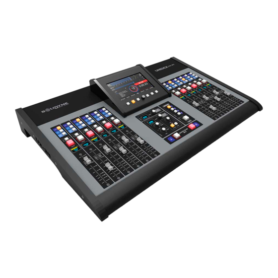
- Page 1 ESPAÑOL & ENGLISH SERIE UNIDEX Manual de desarme y opcionales Disassembly guide and optional’s :consolas: UNIDEX UX24 Agosto 2022 August 2022 WWW:SOLIDYNEPRO.COM...
- Page 2 Manual de desarme y opcionales ESPAÑOL Contenidos 1. Reemplazo de atenuadores 2. Desmontar módulos 8-IN y DANTE AES67 (opción A-67) 3. Desmontar módulo de pantalla táctil 4. Desmontar placa USB 1. Reemplazo de atenuadores En todas las consolas los atenuadores están conectorizados y montados al chasis con tornillos. Su reemplazo con repuestos originales es muy sencillo.
- Page 3 Manual de desarme y opcionales ESPAÑOL 4. Remover los 4 tornillos indicados en la figura 4 y quitar la tapa (según corresponda). En el ejemplo se reemplaza el atenuador número 8, ubicado del lado derecho de la consola. Tenga en cuenta que al dar vuelta el equipo, los atenuadores 7 a 12 quedarán a la izquierda. Figura 4: Tapas de acceso a los atenuadores Figura 5: Atenuadores 7 al 12 (panel derecho) en UX24 5.
- Page 4 Manual de desarme y opcionales ESPAÑOL Figura 7: Remoción de la base 3. Remover en el panel trasero los tornillos de sujeción indicados en la figura. Figura 8: Tornillos de sujeción de la placa 4. Identificar y levantar la placa 8IN o A67 (según el caso) desconectando el cable plano de la placa central.
- Page 5 Manual de desarme y opcionales ESPAÑOL 3. Desmontar módulo de pantalla táctil La torreta central contiene la pantalla táctil y su hardware de control. UX24 sigue siendo operativa aún sin el módulo de pantalla a bordo accediendo vía IP a la interfaz de control web. Para desmontar la pantalla: 1.
- Page 6 Manual de desarme y opcionales ESPAÑOL Figura 12: Conector cable plano 5. Desconecte el conector polarizado (1); el conector RJ45 (2) y el cable de tierra (3). Figura 13: Conector polarizado, RJ45 y tierra 6. El módulo ya puede retirarse. Para re-conectar, siga los pasos anteriores en orden inverso. 6/15...
- Page 7 Manual de desarme y opcionales ESPAÑOL 4. Reemplazar el módulo USB 1. Quitar la base de la consola, siguiendo las indicaciones hechas anteriormente. 2. En el panel trasero remover los 3 tornillos y la tuerca del Jack indicados en la imagen: Figura 14: Tornillos de sujeción traseros 3.
- Page 8 Manual de desarme y opcionales ESPAÑOL 6. Desconectar el cable de alimentación, para manipular las placas con comodidad. 7. Girar la placa y localizar el módulo USB. Luego remover los 2 tornillos indicados en la figura: 8. Desconectar el módulo USB tirando hacia arriba. Figura 15: Tirar para desenchufar el módulo USB Figura 16: Placa sin el módulo USB 8/15...
- Page 9 Disassembly guide and optional’s ENGLISH Contents 5. Faders replacing 6. Swap 8-IN and DANTE AES67 modules (option A-67) 7. Remove the touch-screen module 8. Remove the USB module 1. Faders replacing In all models the faders are connectorized and mounted to the chassis with screws. Its replacement with original spare parts is simple.
- Page 10 Disassembly guide and optional’s ENGLISH 4. Remove the 4 screws indicated in figure 4 and remove the corresponding cover. The example replaces fader number 8, located on the right side of the console. Note that when you flip the unit over, faders 7 through 12 will be on the left. Figure 4: Access to the faders Figure 5: Faders 7 to 12 (right panel) in UX24 5.
- Page 11 Disassembly guide and optional’s ENGLISH Figure 7: Removing the bottom base 3. Remove from rear panel the fixing screws indicated on next illustration. Figure 8: Tornillos de sujeción de la placa 4. Identify and lift the 8IN or A67 board (depending on the case) by disconnecting the flat cable from the central board.
- Page 12 Disassembly guide and optional’s ENGLISH 3. Remove the touch-screen module The central turret contains the touch screen and its control hardware. UX24 remains operational even without the display module on board, accessing via IP to the web control interface. To dismount the screen module: 1.
- Page 13 Disassembly guide and optional’s ENGLISH Figure 13: Flat ribbon cable 5. Disconnect the polarized connector (1); the RJ45 (2) and the ground pin (3). Figure 14: Polarized pug, RJ45 y ground 6. The module can now be removed. To reconnect, follow the steps above in reverse order. 13/15...
- Page 14 Disassembly guide and optional’s ENGLISH 4. Remove the USB module 1. Remove the bottom base of the console, following the indications made previously. 2. On the rear panel remove the 3 screws and the jack nut indicated in the image: Figure 15: Fixing screws 3.
- Page 15 Disassembly guide and optional’s ENGLISH 6. Disconnect the power cable, to handle the circuit boards comfortably. 7. Rotate the board and locate the USB module. Then remove the 2 screws indicated in the figure: 8. Disconnect the USB module by pulling it up. Figure 16: pulling it up to remove the USB Figure 17: Board with USB removed 15/15...
Need help?
Do you have a question about the UNIDEX Series and is the answer not in the manual?
Questions and answers