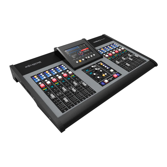
Solidyne UNIDEX UX24 Owner's Manual
Standalone & ip mixer console
Hide thumbs
Also See for UNIDEX UX24:
- Owner's manual (48 pages) ,
- Disassembly manual (15 pages) ,
- Owner's manual (44 pages)
Table of Contents
Advertisement
Quick Links
Advertisement
Table of Contents

Related Manuals for Solidyne UNIDEX UX24


Summary of Contents for Solidyne UNIDEX UX24
- Page 2 Page 2 Solidyne UNIDEX UX24 WWW.SOLIDYNEPRO.COM...
-
Page 3: Table Of Contents
2.5 About the connectors and wiring..........................12 2.5.1 Wiring kits........................................12 2.5.2 RJ45 nomenclature......................................12 2.5.3 RJ45 inputs and outputs....................................12 2.5.4 Solidyne UX24 wiring kits....................................12 2.5.4.1 To RCA (unbalanced)............................................13 2.5.4.2 To balanced XLR............................................. 13 2.5.4.3 To balanced TRS............................................. 13 SECTION 3 UNIDEX EXTERNAL ADAPTERS.................... - Page 4 6.3 REMOTE..................................39 6.3.1 Settings........................................... 40 6.3.2 Mic and line channels..................................... 40 6.3.3 TELCO channels......................................40 6.4 PROCESS...................................41 SECTION 7 DIAGRAMS AND TECH NOTES....................41 Quick installation guides......................................41 Diagrams..........................................41 SECTION 8 TECH SPECS........................... 43 Page 4 Solidyne UNIDEX UX24 WWW.SOLIDYNEPRO.COM...
-
Page 5: Section 1 Overview
The channels can work in 3 modes: MIC; LINE; TELCO. These modes changes functions and the behavior of the channel and sets according Solidyne UNIDEX UX24 is a standalone unit, containing a to the input. fully digital mix engine. It works at 24 bits @ 48 kHz with DSP processing. -
Page 6: Outputs
AES-3 # 1 input). • 1 input for external tuner, used to monitor the transmission on-air. 1.2.3 Outputs UNIDEX UX24 has 18 stereo outputs and 4 outputs for monitoring: • 2 Program (dual): Two PGM analogical bal- anced outputs. •... -
Page 7: Section 2 Connections
The general electrical installation must be properly 2.2.1 Pre-assembled cable kits grounded. As reference, in Section 7 - DIAGRAMS AND Solidyne provides (optionally) kits of cables and APPENDICES you will find a link to a grounding installa- adapters; intended to install the console without weld- tion diagram for an FM station. -
Page 8: Microphones Inputs
48V phantom right if stereo. In this case the connection is made power for each one. Each input uses an RJ45 fe- using adapter cables by Solidyne (or others brands male connector that connects using a SOL- M25/1XLRF cable. -
Page 9: Program Outputs
Download the driver from the following link: ht tp://solidynePRO.com/DW/Solidyne_UsbAudio.zip 2.3.7 Analog outputs Run the setup and follows the instructions. UNIDEX UX24 have 8 stereo analog outputs: Once installed, Windows shows four Solidyne USB out- • 4 balanced (electronically), put devices, and four Solidyne USB input devices. -
Page 10: Dante - Aes67 (Optional)
Incoming streaming can be RTP or public http stream- ONLY THE “STUDIO MONITOR” ADAPTER PATCH CORD PRO- ing. When the incoming streaming option is enabled, the VIDED WITH THE UNIT can be used when the Solidyne Stu- dioBox is not available. decoded audio is automatically switched (replaces) to the AES 1 input. -
Page 11: Monitoring In The Control Room
4 inputs and 8 outputs. The GPIs allows to com- mand some UX24 features like mics activation. GPOs can trigger external devices, such as “on-air” signaling lights; the Solidyne Audicom software or the audio pro- cessor. • The 4 GPI supports trigger signals from 5 to 15V / 150mA (active high). -
Page 12: Configure The Gpio Behavior
2.5.1 Wiring kits 6 Right channel (-) Green 7 -15 (option) Brown/White Solidyne can provide all cables and adapters patch cords 8 +15 (option) Brown needed to the installation. See the following links for de- tails. UNBALANCED INPUTS / OUTPUTS http://www.solidynepro.com/consola-de-audio-de-bc-... -
Page 13: To Rca (Unbalanced)
NOTE The RJ45 microphone inputs in the back panel uses only the left chanel o the balanced connection. Solidyne provides the cables SOL-M25/1XLRF and SOL- M12/1XLRF to connect microphones (single XLR to RJ45). 2.5.4.3 To balanced TRS 2.5.4.2 To balanced XLR WWW.SOLIDYNEPRO.COM... -
Page 14: Section 3 Unidex External Adapters
3.2.2 Inputs settings 3.2.1 Setting up UDX 2MIC is connected to a balanced UNIDEX input, us- ing a single STP RJ45-RJ45 cable (Solidyne SOL-P50 or SOL-P25 cables). Microphones connects to the UDX adapter using stan- dard XLR. UDX 2MIC has -10dB pad dip- switches. -
Page 15: Channel Configuration
Section 7 – Diagrams and tech notes. Using input UNIDEX 3 and output UNBAL 7 Using input UNIDEX 4 and output UNBAL 8 REMEMBER SAVE THE CURRENT SCENE TO STORE THE SET- TINGS AND CONFIGURATIONS. WWW.SOLIDYNEPRO.COM Solidyne UNIDEX UX24 Page 15... -
Page 16: Connection To Phone Lines
NOTE In the event that a nearby electric shock burns the thermal fuse protection, you can ask Solidyne to replace the tele- phone line protection circuit. WARNING Telephone lines in rural areas must have a gaseous pro- tector against voltage spikes, for protection against light- ning or lightning strikes. -
Page 17: Outputs Setings
3.3.4 Channel settings REMEMBER SAVE THE CURRENT SCENE TO STORE THE SET- TINGS AND CONFIGURATIONS. To download a Quick Installation Guide (pdf) for this UDX adapter, go to Section 7 – Diagrams and tech notes. WWW.SOLIDYNEPRO.COM Solidyne UNIDEX UX24 Page 17... -
Page 18: Udx Tel+Bt
To download the Quick Installation Guide (pdf) go to Section 6 – Diagrams and tech notes. 3.5 UDX USB This adapter allows to connect a computer, via USB, with one AES3 input and one AES3 output. 3.5.2 Output setup Page 18 Solidyne UNIDEX UX24 WWW.SOLIDYNEPRO.COM... -
Page 19: Channel Settings
3.6 StudioBox HD3 & HD5: 3.5.3 Channel settings monitoring into the Studio The modules for monitoring Solidyne StudioBox HD5 and HD3 resolve the sending of all monitoring signals to the studio. 3.6.1 CONNECTING The HD3/HD5 accessories are connected to the “Moni- tor Studio”... -
Page 20: Using The Studiobox
About the headphones into the Studio tor will use the talk-back as is usual to talk with the Studio. The Solidyne HD5 accessory manages up to five head- phones with independent level knobs. When the mics are on the air, the Intercom button only works as a tally light. -
Page 21: Section 4 Start Up And Routing
STEREO BAL 9 default boot profile must be changed to BASIC or EX- USB-01 LINE USB1 L&R PERT. For more details please see 4.9 SETTINGS / USB-02 LINE USB2 L&R USERS. USB-03 LINE USB3 L&R WWW.SOLIDYNEPRO.COM Solidyne UNIDEX UX24 Page 21... -
Page 22: Settings
2 AUDIO INPUTS When a UNIDEX input is used as a balanced line input, List of all available audio inputs in the UNIDEX UX24. To UDX TYPE must be LINE (default). navigate the list, turn the encoder. At the right, the options and settings of the selected input are displayed. -
Page 23: Output List
NUS of PGM is sent to the line; that is, the PGM signal MI- Start on-air input: Select an input. It can be assigned to a NUS the telephone line audio. channel (hardware or virtual). The console always starts WWW.SOLIDYNEPRO.COM Solidyne UNIDEX UX24 Page 23... -
Page 24: Network Settings (Ethernet Control)
IP address. It is used to create A streaming RTP for point to point link. point-to-point links, for example, to send the program sig- A streaming for upload to servers type icecast/ nal to the transmission plant (STL). shoutcast Page 24 Solidyne UNIDEX UX24 WWW.SOLIDYNEPRO.COM... -
Page 25: Down-Stream (Rx)
(ADMIN) to BASIC or EXPERT, depending on the level of restriction needed. If the console starts with a BASIC profile, passwords for EXPERT or ADMIN must be known in order to access restricted features. WWW.SOLIDYNEPRO.COM Solidyne UNIDEX UX24 Page 25... -
Page 26: Aoip
4.10 AoIP UNIDEX UX24/A67 has the module DANTE for 16x16 net- worked audio. This screen shows the settings and status of DANTE network. The DANTE network and devices con- figures from DANTE Controller software. Download in the following link an example for the imple- mentatios of DANTE and UX24. -
Page 27: Section 5 Operation
The PGM meter remains visible on all screens and can be Stream IP: Destination IP address for streaming. switched to other buses by tapping on the text “PGM”. SCENE: Indicates the current scene. WWW.SOLIDYNEPRO.COM Solidyne UNIDEX UX24 Page 27... -
Page 28: Channels
The most important 5.3 Channels item is the safety shutdown for the internal CPU. UNIDEX UX24 is a 24-channel mixing console. In the basic 4 MAIN CLOCK: Shows the current time. The time syn- configuration, it has 12 channels with 100mm "real"... -
Page 29: Monitoring Section
CUE signal is present. The degree of attenua- tion can be defined in the MONITOR section. The CUE bus can be assigned to any output, for connec- tion of auxiliary speakers. By default, it is assigned to UN- BAL 8. WWW.SOLIDYNEPRO.COM Solidyne UNIDEX UX24 Page 29... -
Page 30: Screen Monitor
When do it, the encoder returns to the naviga- tion mode. To confirm the selection press the SELECT button. When confirming, the SELECT mode Functions Intercom to CUE and CUE to speaker is disabled. are toggled by touch screen. Page 30 Solidyne UNIDEX UX24 WWW.SOLIDYNEPRO.COM... -
Page 31: Channel Screen
PGM, REC and the edit mode. AUX buttons. For virtual channels, they allow you to as- sign a channel to the different buses. In both, you can as- WWW.SOLIDYNEPRO.COM Solidyne UNIDEX UX24 Page 31... - Page 32 The ADMIN- ISTRATOR user can access the configuration by touching SETTINGS. 8 ACTIONS: Special features that defines the channel behavior. The eatures depends on the channel’s MODE. Page 32 Solidyne UNIDEX UX24 WWW.SOLIDYNEPRO.COM...
-
Page 33: Telco - Comunications
3 LEVEL: Shows the level of the received signal. It also indicates the name of the input used by the UNIDEX Connect to SOLIDYNE BTM641. The mobile is now adapter. paired and linked with UNIDEX adapter. If Bluetooth is turned off on the mobile, the TELCO... -
Page 34: Working With Calls
With adequate levels of work this effect is not noticeable; but if the hybrid is SELECT A CHANNEL: mixed at high levels the voices from the studio can “get dirty” (coloration). Page 34 Solidyne UNIDEX UX24 WWW.SOLIDYNEPRO.COM... -
Page 35: Parametric Ecualizer
PROCESS screen. To switch its status, touch the 5.9.1 PARAMETRIC ECUALIZER icon on screen.. 5 – SELECT: Switchs on the mode SELECT, to choose a channel and make an action. 6 – BACK: Returns to previous screen. Navigation WWW.SOLIDYNEPRO.COM Solidyne UNIDEX UX24 Page 35... -
Page 36: Dynamics
This option changes the recovery time be- pliqued, in dB. tween preset values. ACTIVE: This indication lights red when the gate closes. COMPRESSOR: Adjustment values for the com- pressor. BYPASS: Disable the Dynamic processing. Page 36 Solidyne UNIDEX UX24 WWW.SOLIDYNEPRO.COM... -
Page 37: Scenes And User Profiles
CHANNEL SAVE: Saves the current settings, assignments, and pro- screen. cessing settings to the active scene. The scene does not WWW.SOLIDYNEPRO.COM Solidyne UNIDEX UX24 Page 37... -
Page 38: Virtual Mixer
Allows you to swap the order of two channels: Touch the option SWAP 2 CH. UNIDEX UX24 manages 12 virtual channels in standard Select two channels from the list. model, or 6 when is expanded with the extension UDX 6 which adds 6 hardware channels. -
Page 39: Section 6 Web Remote Interface
POTS) or manage auxiliary signals. The main screen will open, showing the level indicators The monitoring panel allows to use the web interface as and a main menu. a full secondary mixer into auxiliary Studio. WWW.SOLIDYNEPRO.COM Solidyne UNIDEX UX24 Page 39... -
Page 40: Settings
Talk-back and dial functions must be done from the console surface. Each channel of the interface replicates the controls available on the UX24 hardware surface. Actions taken on the remote interface are reflected in the console. Page 40 Solidyne UNIDEX UX24 WWW.SOLIDYNEPRO.COM... -
Page 41: Process
Adapter UDX 2TEL y 2TEL-P Adapter UDX TEL+BT Diagrams Inputs and outputs map UX24 scenes default routing GROUNDING: General recommendation for a radio station Cables and kits for the installing Listing of cables and adapters (PDF) WWW.SOLIDYNEPRO.COM Solidyne UNIDEX UX24 Page 41... - Page 42 EMPTY PAGE Page 42 Solidyne UNIDEX UX24 WWW.SOLIDYNEPRO.COM...
-
Page 43: Section 8 Tech Specs
SECTION 8 TECH SPECS Main Features • 24 channels; 12 faders on console’s surface, expandible to 24 with 6-faders modules Solidyne UX-6. • 24 virtual faders can be operated from the on-board touch screen. • Internal WEB pages remote interface (HTML5) to remote control via LAN. - Page 44 • Packaging dimensions: 850 mm x 610 mm x 270 mm • Wheight: UX24= 8 Kg Adapters UDX: 0,33 Kg each one Kit cables RJ45: 4 Kg With packaging UX24 + Cables= 15 Kg Page 44 Solidyne UNIDEX UX24 WWW.SOLIDYNEPRO.COM...
Need help?
Do you have a question about the UNIDEX UX24 and is the answer not in the manual?
Questions and answers