
Related Manuals for Balluff BTL7-E508-M P-S32/KA Series


Summary of Contents for Balluff BTL7-E508-M P-S32/KA Series
- Page 1 BTL7-C/E508-M _ _ _ _ -P-S32/KA _ _ BTL7-C/E509-M _ _ _ _ -P-S32/KA _ _ BTL7-C/E512-M _ _ _ _ -P-S32/KA _ _ BTL7-C/E513-M _ _ _ _ -P-S32/KA _ _ User's Guide english...
- Page 2 www.balluff.com...
-
Page 3: Table Of Contents
Accuracy Ambient conditions Supply voltage (external) Output Communication lines La, Lb Dimensions, weights Accessories Captive magnets BTL2-GS10-_ _ _ _-A joint rod Floating magnets Connectors and cables 8.4.1 BKS-S32/S33M-00, freely configurable 8.4.2 BKS-S232/S233-PU-_ _, preassembled USB communication box www.balluff.com english... - Page 4 BTL7-C/E5_ _-M _ _ _ _ -P-S32/KA _ _ Micropulse Transducer in a Profile Housing Type code breakdown Appendix 10.1 Converting units of length 10.2 Part label english...
-
Page 5: Notes To The User
Severity level 2 – Conducted interference induced by high-frequency fields Severity level 3 EN 61000-4-6 – Magnetic fields EN 61000-4-8 Severity level 4 More detailed information on the guidelines, approvals, and standards is included in the declaration of conformity. www.balluff.com english... -
Page 6: Safety
The warnings used here contain various signal words and in accordance with the specifications in the technical data are structured as follows: is ensured only when using original BALLUFF accessories. SIGNAL WORD Use of any other components will void the warranty. -
Page 7: Construction And Function
Magnet: Defines the position to be measured on the waveguide. Magnets are available in various models and must be ordered separately (see Accessories on page 18). Nominal length: To optimally adapt the transducer to the application, nominal lengths from 50 mm to 7620 mm are available. www.balluff.com english... -
Page 8: Function
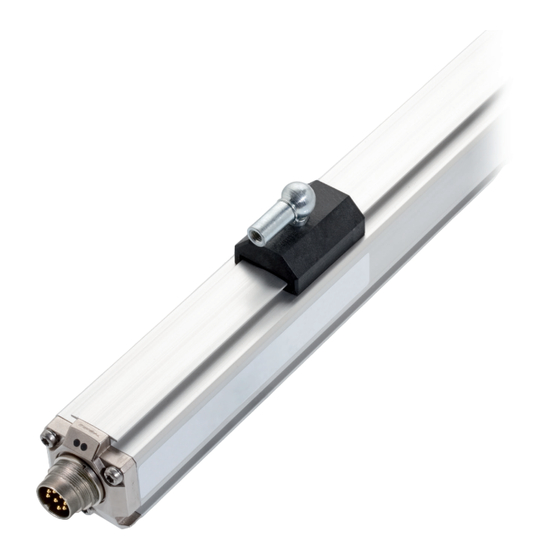
BTL7-C/E5_ _-M _ _ _ _ -P-S32/KA _ _ Micropulse Transducer in a Profile Housing Construction and function (continued) Function LED display The BTL7 transducer contains the waveguide which is LED 1 LED 2 protected by an aluminum housing. A magnet is moved along the waveguide. -
Page 9: Installation And Connection
(see Fig. 4-1 to Fig. 4-3). Fig. 4-2: Dimensions and distances with BTL5-T-2814-1S magnet Fig. 4-3: Dimensions and distances with BTL5-M/N-2814-1S magnet BTL5-M-2814-1S BTL5-N-2814-1S Distance X 48.5 mm 57 mm Distance Y 51 mm 59.5 mm Tab. 4-1: Distances with BTL5-M/N-2814-1S magnet www.balluff.com english... -
Page 10: Floating Magnets
BTL7-C/E5_ _-M _ _ _ _ -P-S32/KA _ _ Micropulse Transducer in a Profile Housing Installation and connection (continued) Floating magnets The following must be observed when installing the magnet: – To ensure the accuracy of the position measuring system, the magnet is attached to the moving member of the machine using non-magnetizable screws (stainless steel, brass, aluminum). -
Page 11: Electrical Connection
Unassigned leads can be connected to the GND on the controller side but not to the shield. Factory setting, can be freely configured with the PC software. Referred to as output 2 in PC software. Reference potential for supply voltage and EMC-GND. Tab. 4-3: Pin assignment of connector S32/KA_ _ www.balluff.com english... -
Page 12: Shielding And Cable Routing
BTL7-C/E5_ _-M _ _ _ _ -P-S32/KA _ _ Micropulse Transducer in a Profile Housing Installation and connection (continued) Shielding and cable routing Defined ground! The transducer and the control cabinet must be at the same ground potential. Shielding To ensure electromagnetic compatibility (EMC), observe the following: –... -
Page 13: Startup
Operating notes – Check the function of the transducer and all associated components on a regular basis. – Take the position measuring system out of operation whenever there is a malfunction. – Secure the system against unauthorized use. www.balluff.com english... -
Page 14: Configuration With The Micropulse Configuration Tool
– Demo mode without having transducer connected Controller The PC software and associated manual can be 8-pin found in the Internet under www.balluff.com. Connection cable USB cable approx. 0.6 m with luster terminal Fig. 6-2: Connecting the communication box with a cable connection When reading or writing data via the Configuration Tool, LED 2 flashes green. -
Page 15: Configuration Options
The additional voltage output (output 2) can also be inverted. Changing the null or end point also affects the additional voltage output. Even if the output values (current output) are changed, the characteristic curve of the additional voltage output remains at 0…10 V or 10…0 V. www.balluff.com english... -
Page 16: Technical Data
: Use in enclosed spaces and up to a height of 2000 m above sea Storage temperature −40°C…+100°C level. Relative humidity < 90%, Individual specifications as per Balluff factory standard non-condensing Resonant frequencies excluded : The transducer must be externally connected via a limited- Shock rating 150 g/6 ms energy circuit as defined in UL 61010-1, a low-power source as defined in... -
Page 17: Communication Lines La, Lb
Dimensions, weights Housing height 36.8 mm Nominal length 50…7620 mm Weight (depends on length) Approx. 1.4 kg/m Housing material Aluminum BTL7-…-KA_ _ Cable material cULus 20549 80 °C, 300 V, internal wiring Cable temperature –40°C…+90°C Cable diameter Max. 7 mm Permissible bending radius Fixed routing ≥ 35 mm Moved ≥ 105 mm www.balluff.com english... -
Page 18: Accessories
BTL7-C/E5_ _-M _ _ _ _ -P-S32/KA _ _ Micropulse Transducer in a Profile Housing Accessories Captive magnets BTL2-GS10-_ _ _ _-A joint rod Nominal length BTL5-M/N-2814-1S Mechanically joined to M5 stud using 2 nuts Adjustment range −5 mm Fig. 8-1: Installation dimensions of BTL5-M/N-2814-1S magnet Fig. -
Page 19: Floating Magnets
Special advantage of the BTL5-P-4500-1 magnet: Several magnets on the same transducer can be separately switched on and off electrically (actuation BTL6-A-3800-2 with a PLC signal). 37.6 Ø 4.2 Fig. 8-7: Installation dimensions of BTL6-A-3800-2 magnet Weight: Approx. 30 g Housing: Plastic www.balluff.com english... -
Page 20: Connectors And Cables
BTL7-C/E5_ _-M _ _ _ _ -P-S32/KA _ _ Micropulse Transducer in a Profile Housing Accessories (continued) Connectors and cables BKS-S233-PU-_ _ Angled connector, molded, preassembled M16, 8-pin Various cable lengths can be ordered, e.g. BKS-S233-PU-05: Cable length 5 m 8.4.1 BKS-S32/S33M-00, freely configurable Ø... - Page 21 13 = 1 falling current output, configurable + 1 falling voltage output Nominal stroke (4-digit): M0500 = Metric specification in mm, nominal length 500 mm (M0050…M7620) Construction: P = profile housing Electrical connection: S32 = 8-pin, M16 plug per IEC 130-9 KA05 = Cable, 5 m (PUR) www.balluff.com english...
- Page 22 BTL7-C/E5_ _-M _ _ _ _ -P-S32/KA _ _ Micropulse Transducer in a Profile Housing Appendix 10.1 Converting units of length 1 mm = inch 1 inch = 25.4 mm inches inches 0.03937008 25.4 0.07874016 50.8 0.11811024 76.2 0.15748031 101.6 0.19685039 0.23622047 152.4...
Need help?
Do you have a question about the BTL7-E508-M P-S32/KA Series and is the answer not in the manual?
Questions and answers