
Subscribe to Our Youtube Channel
Related Manuals for SeasonsComfort Sarmateo


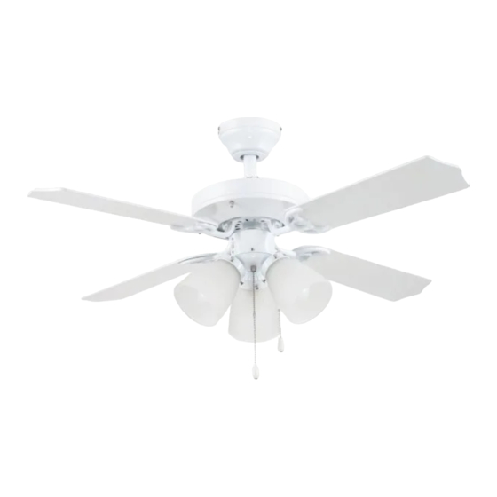
Summary of Contents for SeasonsComfort Sarmateo
- Page 1 Part #: 269800 Sarmateo™ 42” LED Ceiling Fan Owner’s Manual Exclusively Distributed By: To Reorder: HD Supply Facilities Maintenance, Ltd. 1-800-431-3000 Atlanta, GA 30339 hdsupplysolutions.com © 2019 Made in China...
-
Page 2: Package Contents
PACKAGE CONTENTS Unpack your fan and check the contents. You should have the following items: PACKAGE CONTENTS 1. Canopy 12. Glass Shade (x3) 2. Canopy Cover 13. Switch Housing Cap 3. Mounting Bracket 14. Bulb (x3) 4. Downrod 15. Blade (x4) 5. -
Page 3: Mounting Options
DIMENSION REFERENCE A. 18.56 in. B. 12.9 in. C. 10.76 in. D. 9.41 in. E. 5.13 in. MOUNTING OPTIONS Tri-mount Options Closemount Downrod Mount Angled Ceiling Mount (Up to 16 degrees) Choose one of the following mounting options: Closemount method is best suited for ceilings lower than 8 feet. It does not utilize the downrod. Downrod Mount is best suited for ceilings 8 ft. -
Page 4: Safety Instructions
SAFETY INSTRUCTIONS READ ALL SAFETY INFORMATION AND INSTALLATION INSTRUCTIONS BEFORE YOU BEGIN INSTALLING THE FAN AND SAVE INSTRUCTIONS. CAUTION: All set screws of the fan must be checked and retightened where necessary before installation. To reduce the risk of personal injury, do not bend the blade brackets when installing the brackets, balancing the blades or cleaning fan. - Page 5 ASSEMBLY INSTRUCTIONS 1. Turn OFF the electrical power at the main fuse or circuit breaker. 2. Remove the mounting bracket by removing the two Mounting mounting bracket screws from the round holes in the Bracket Screw canopy. Then loosen the other two mounting bracket screws from the J-shaped slots.
- Page 6 ASSEMBLY INSTRUCTIONS 5. DOWNROD MOUNT - Remove the downrod pin and downrod clip from the downrod. Then, loosen but don’t remove the two set screws at the top of the yoke. Downrod Downrod Clip Downrod Set Screw Yoke 6. Feed the wires coming from the yoke through the canopy and downrod.
- Page 7 ASSEMBLY INSTRUCTIONS 9. Use wire connectors to connect the fan wires to the Black (Hot) power supply wires according to the wiring diagram and the following instructions: White (Neutral) Bare/Green (Ground) • Connect the green wire from the downrod and mounting Wire Connector bracket to the bare/green (ground) supply wire.
- Page 8 ASSEMBLY INSTRUCTIONS To install the fan without the light kit, skip to step 17. 13. Remove the three switch housing screws from the top edge of the light kit. Then, connect the single-pin connectors from the fan to the single-pin connectors from Reverse Switch the light kit -- blue to black and white to white.
- Page 9 ASSEMBLY INSTRUCTIONS 17. INSTALLATION WITHOUT LIGHT KIT (OPTIONAL) a. Remove the three switch housing screws from the switch housing at the top of the light kit. b. Attach the switch housing cap to the switch housing using the three previously removed switch housing Reverse screws.
-
Page 10: Troubleshooting
TROUBLESHOOTING If you have difficulty operating your new ceiling fan, it may be the result of incorrect assembly, installation or wiring. In some cases, these installation errors may be mistaken for defects. If you experience any faults, please check the Troubleshooting section below. If a problem cannot be remedied or you are experiencing difficulty in installation, please contact Customer Service: 1-800-431-3000. -
Page 11: Manufacturer Warranty
MANUFACTURER WARRANTY To contact Customer Service: 1-800-431-3000. Model Name: Seasons® Sarmateo™ 42” LED Ceiling Fan HDS Part #: 269800, Mfg #: 32158 (White) Subject to the limitations set forth below, Hong Kong China Electric appliance Company (HKC) warrants the fan motor for this ceiling fan to be free from defects in workmanship and material for the life of the product.
Need help?
Do you have a question about the Sarmateo and is the answer not in the manual?
Questions and answers