Table of Contents
Advertisement
Quick Links
Advertisement
Table of Contents

Related Manuals for Wasp 4070 HDP


Summary of Contents for Wasp 4070 HDP
- Page 1 WASP 4070 HDP MANUAL OF USE AND MAINTENANCE ORIGINAL INSTRUCTIONS...
- Page 2 The missing acknowledgment of the manual can be cause of personal injury, worst quality results or damages to the printer WASP 4070 HDP. Always make sure that the operators using the 3D printer knows and understands the content of the manual in order to achieve the best results from WASP 4070 HDP.
-
Page 3: Table Of Contents
5.2.6. GCODE ..................39 9.1. General warnings ..............90 5.2.7. PRINTING board ...............40 9.2. Disposal and dismantling ..........90 5.2.8. TUNE menu .................41 9.3. Instructions for emergency situations ....... 91 5.2.9. Digit window................42 5.3. First start ................. 43 © WASP S.r.l. -
Page 5: Introduction
We accept no responsibility for damage to persons or property resulting from improper use and / or omitted or inadequate maintenance. • The recipient has the right to request further information. In case of loss and/or damage of the present Manual it is responsibility of the recipient to ask for one or more copies. © WASP S.r.l. -
Page 6: How To Read The Manual Of Instructions
The sending of any additional parts is the responsibility of the Manufacturer; the user is responsible for the replacement of parts that may be altered as a result of use, making a request directly to the Manufacturer. © WASP S.r.l. -
Page 7: General Information
220v-240v WASP s.r.l. via Castelletto 104 Massa Lombarda (RA) Italy www.3dwasp.com Stampante 3D Modello: WASP 4070 HDP Rif. TCF: WASP 4070 HDP Input: 220V-240V 50/60Hz Potenza Max: 2400W Corrente a pieno carico: 9,8A Anno di produzione: 2022 Numero di serie:... -
Page 8: Position Of The Label On The Printer
The printer is tested directly by the Manufacturer during the phase of assembly and testing. 1.4. Warranty The printers built by WASP S.r.l. are covered by warranty for a period of 12 months for companies or VAT and 24 months for individuals, according to the specifications set out in the sales contract. -
Page 9: General Safety Warnings
• which must be the characteristics of the maintenance operators. WASP is not responsible for unspecified operations, as they are considered strictly pertinent to technical assistance personnel or for operations performed differently from what we described in the documentation presented. -
Page 10: Operators For Whom The Manual Is Intended
This risk exists during the removal phase of the filament from the extruder and during the removal of the piece from the plate. CAUTION: Remove the part only when both the extruder and the bed are cool. ATTENTION: During the operations on the machine the user must wear protective gauntlets. © WASP S.r.l. - Page 11 Maintenance / cleaning operations must be carried out by trained and authorized personnel. Operations must be performed in a safe stop condition, disconnecting the printer from power sources. Refer to chapter 7 “Ordinary and Extraordinary Maintenance”. Legend: Hot surfaces, pay attention not to touch when heated © WASP S.r.l.
-
Page 12: Safety Stickers
He/she is able to operate in the presence of voltage inside enclosures and junction boxes Manufacturer Technician Qualified technician provided by WASP S.r.l. to carry out operations of a complex nature in particular situations or in any case according to what has been agreed with the user. -
Page 13: Editorial Pictograms
Indicates the need to use safety shoes suitable for performing the described operation. PROTECTIVE WORKWEAR: Indicates the need to use protective clothing to perform the operation described. PROTECTIVE HELMET: Indicates the need to use a safety helmet to perform the operation described. © WASP S.r.l. - Page 14 INTRODUCTION © WASP S.r.l.
-
Page 15: Description Of The Printer
The toolpaths are defined by the file produced with the use of a slicing software. It’s possible, in this way, to create any shape and kind of object within the limits of this technology. Fig. 2 - Printer © WASP S.r.l. -
Page 16: Control Panel
Printing Machine busy in a printing process Yellow Paused Machine paused or waiting for a material refill Cancelling/error Machine cancelling an operation or sending an error message 4. TFT touch Operator display (see paragraph 5.2 “User Interface”) © WASP S.r.l. -
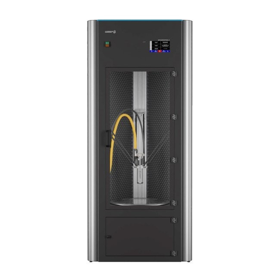
Page 17: Work Area
Fig. 2.2 - Work area Legend: 1. Cable carrier 2. Door handle 3. Carbon fiber rods 4. Material hose 5. HDP Extruder 6. HEPA filters 7. Chamber heaters 8. Sliders 9. VACS - Vacuum Active Control System (see paragraph 8.12) © WASP S.r.l. -
Page 18: External Area Of The Printer
2.3. External area of the printer Fig. 2.3 - External area of the printer Legend: 1. Ethernet door (for static IP cable connection) 2. Material tank 3. Label 4. Power socket 5. TFT touch Operator display 6. Storage area © WASP S.r.l. -
Page 19: Tank (Material Storage)
5. Discharge opening 6. Pressure gauge 7. Compressed air inlet (connect with a flexible hose of 8 mm of external diameter from the compressor) 8. Moisture filter 9. Material outlet (connected with material hose in par 2.2 “Work area”) © WASP S.r.l. -
Page 20: Vacs - Vacuum Active Control System
Description of the printer INTRODUCTION 2.5. VACS - Vacuum Active Control System Fig. 2.5 - VACS - Vaacum active control system Legend: 1. Aluminum vacuum bed 2. Silicon gasket 3. Removable printing plate © WASP S.r.l. - Page 21 Description of the printer INTRODUCTION 2.6. Extruder Fig. 2.6 - Extruder Legend: 1. Pellet hose 2. Extruder screw 3. Pellet hopper 4. Heatsink 5. Barrel 6. Cooling fan 7. Nozzle © WASP S.r.l.
-
Page 22: Technical Data
Pellet diameter max 4x4 mm Suitable filaments PLA, ABS, ASA, PP, TPE, PETG Interface and software Operative systems Windows, Mac, Linux Supported slicing software Simplify3D File formats .stl, .obj, .gcode Interface USB pendrive, TFT touch display, Wi-Fi © WASP S.r.l. -
Page 23: Intended Use Of The Printer
• the cancellation of the Manufacturer’s Responsibility for damages caused to people, things or animals. ATTENTION Improper use can damage the printer which consequently can cause dangerous situations for the personnel responsible for its operation and maintenance. © WASP S.r.l. -
Page 24: Transport And Handling
(with a temperature between 0 ° C and 30 ° C and relative humidity between 20 % and 60% non-condensing) and protected from atmospheric agents in order to avoid deterioration. ATTENTION: During storage, never stack the boxes containing the equipment. © WASP S.r.l. -
Page 25: Unpacking, Lifting And Handling Of The Printer
All small equipment that exceeds the weight of 25 kg must be transported with the appropriate equipment, or manually (if not exceeding 50 Kg) by two qualified operators. ATTENTION: The handling of the machine requires three properly qualified persons as mentioned above © WASP S.r.l. - Page 26 Before handling the machine make sure to remove the wooden fixture placed close to the extremity of the machine. Don’t throw this component away as it’s part of the packaging and needs to be stored. DO NOT REMOVE PROTECTIVE FOAM BEFORE THE MACHINE IS STANDING (fig 3.2b) © WASP S.r.l.
- Page 27 Using the two handles positioned on the top of the machine the operators 1 and 2 will start lifting the machine. The operator 3 will guide the machine on the other side preventing it from sliding. (fig 3.2 d) © WASP S.r.l.
- Page 28 Using the two handles positioned on the top of the machine the operators 1 and 2 will continue lifting the machine. The operator 3 will guide the machine on the other side preventing the machine from falling freely. In this phase is especially important to pay attention to the feet. (fig 3.2 f) © WASP S.r.l.
- Page 29 Fig. 3.2h - Positioning the machine If the machine must be moved in more complex ways carry out these operations with maximum care and attention. Do not ever for any reason move the machine without the following recommendations(fig 3.2h) © WASP S.r.l.
- Page 30 LEVELING FOOT 1 WHEEL 1 /NO BRAKE LEVELING FOOT 3 WHEEL 3 / BRAKE LEVELING FOOT 2 WHEEL 2 / BRAKE Fig. 3.2i -Removing the rubber pads and assembling the optional wheels © WASP S.r.l.
-
Page 31: Installation
Do not place the printer near sources of heat, water or other free liquids. Do not install the printer without the appropriate protections. NOTE: A good installation as well as giving greater rigidity to the printer, avoids vibrations and noises. © WASP S.r.l. -
Page 32: Electrical Connection
ATTENTION: The printer must be powered by a compressor with at least 50 liters of capacity and minimum pressure 6 bars. The hose for the connection must be 8 mm in the external diameter. © WASP S.r.l. -
Page 33: Preparing To Use The Printer
Furthermore, the specific requirements for safe interaction with the printer, related to this chapter, are detailed in the following paragraphs. ATTENTION: The operations related to these activities must be performed by authorized and professionally qualified personnel. ATTENTION: During operations, the operator must wear all the necessary Personal Protective Equipment (PPE). © WASP S.r.l. -
Page 34: User Interface
When connected the WIFI icon is green, when disconnected the icon is red. 5. State of the machine v, Autocalibration ENABLED/DISABLED 6. Heated chamber (click to set new target temperature) - Door OPEN/CLOSED When VACS is active VACUUM icon is green, when disabled the icon is white © WASP S.r.l. -
Page 35: Print Menu
3. Vacuum System: Enables or disables VACS(Vacuum Active Control System) The switch shows current state ON or OFF. Learn more in paragraph 8.12 “VACS (Vacuum Active Control System) 4. Start print: access to gcodes list to proceed with the printing (see par. 5.2.6 “GCODE”) © WASP S.r.l. -
Page 36: Prepare Menu
Legend: • Free Zeta system: enters in Free Zeta System Learn more in paragraph 8.6 “Free Zeta System” • Disable motors: disables all stepper motors on the machine ● Autocalibration: Perform autocalibration procedure (see par. 8.2 “Autocalibration” © WASP S.r.l. -
Page 37: Advanced Menu
SETTINGS: Delta Settings, Continuous print, Extruder settings, Motion settings, Temperature settings, Bed touch, Filament sensor, Out of Plate Blocking, Access information, WIFI settings • MODE: Send arbitrary commands, Reload UI, Test Mode, Camera • TOOLS: Set Z Max, Manual Control, Manual Levelling © WASP S.r.l. -
Page 38: Wifi Settings
2. PWD: Allows to insert a password, if present 3. AUTH: makes you specify what kind of connection you’re working with 4. USER: Allows to insert use (if present) Clicking UPDATE the machine restarts with new settings © WASP S.r.l. -
Page 39: Gcode
From PRINT menu, by chosing GCODE you can launch gcodes and moving them from the USB to the printer. The gcodes are loaded in the machine as explained in detail in paragraph 8.7 “Loading .gcode” Legend: 1. Chose to navigate USB Drive 2. Chose to navigate Printer Drive 3. GO: launchs selected print © WASP S.r.l. -
Page 40: Printing Board
PAUSE: Pause the print with the possibility to resume it afterwards. STOP&SAVE: Stop the print with the possibility to resume it afterwards with Resurrection System. STOP: Abort the print without the possibility to resume it. Temperatures won’t cool down after stopping. © WASP S.r.l. -
Page 41: Tune Menu
4. Fan: allows to set an user defined value for the fan (standard is 0 and max is 255, to tune use + and - button and wait 3 seconds) NOTE: this value doesn’t take into account the value for the fan set on the gcode © WASP S.r.l. -
Page 42: Digit Window
The digit window is used when is necessary to define a numeric value. Use the button to digit the desired value and confirm with the green button SET. Use the CANC button to erase a digit. Use BACK to exit the digit window. © WASP S.r.l. -
Page 43: First Start
Inside the printer there are three belts necessary for moving the extruder during printing. To avoid movements of the extruder during transport, clamps are applied on the straps, this have to be removed before starting the print. © WASP S.r.l. -
Page 44: First Use Of The Printer
Open the slicing software (eg Simplify3D) and load the .fff profile. Load the .stl model and set the print parameters. Save the .gcode inside the USB and insert it in the printer or use instead the wifi network. © WASP S.r.l. -
Page 45: Autocalibration
During the CLEAN EXTRUDER command the machine will purge the previous material. In case there’s a consistent difference (more than ± 20°C) consider using a average temperature between the two for purging. Learn more on the loading material procedure in paragraph 8.7 “Loading the material”. © WASP S.r.l. -
Page 46: Placing The Printing Plate On The Vacuum Bed
Hold the printing plate and detach the print by practicing a slight bending on the plate or with the help of a spatula just if neccessary. For information and support please visit F.A.Q. section on our website: www.3dwasp.com © WASP S.r.l. -
Page 47: Ordinary And Extraordinary Maintanance
Pay particular attention during the various stages of the procedures, it is essential to wear gauntlets because there is a risk of burns. ATTENTION: During operations, the operator must wear all the necessary Personal Protective Equipment (PPE). © WASP S.r.l. -
Page 48: Ordinary Maintanance
Sliders Check plays 160 h Par 7.2.4 Nozzle Cleaning and replacement If clogged Par 7.2.5 HEPA filter Replacement 320 h Par 7.2.6 Moisture filter Discharge 160 h Par 7.2.7 Ooze shield protecion Replacement If damaged Par 7.2.8 © WASP S.r.l. -
Page 49: Belts
Check the mobility / stiffness of the arm joints. Apply machine tool lubricant and gently move them manually. Wipe off excess oil This will preserve the optimal functioning of the mechanics. fig 7.2.6 a fig 7.2.6 b Fig. 7.3.1- Ball joints lubrication © WASP S.r.l. -
Page 50: Fans
If one or more of the fans are not working contact the Manufactureraddressing support@3dwasp.com 7.2.4. Sliders Check plays Check that the arm sliders do not have any play between them and the sliding aisle, if it is present, contact the Manufacturer. Fig. 7.2.4 - Check plays on the sliders © WASP S.r.l. - Page 51 Ordinary and extraordinary maintanance INTRODUCTION © WASP S.r.l.
-
Page 52: Nozzle
Ordinary and extraordinary maintanance INTRODUCTION 7.2.5. Nozzle Changing the nozzle Changing nozzle is only recommended when: • The print looks inconsistent due to a clogging • The nozzle is damaged or consumed Fig. 7.2.6 - Cleaning the nozzle © WASP S.r.l. - Page 53 6. Fix the Silicone Ooze shield protection as described in par. 7.2.8 “Ooze shield protection” 7. Use the PRINT>CLEAN EXTRUDER command After a nozzle replacement is recommended to perform the Autocalibration procedure (see paragraph 8.2 Autocalibration). fig 7.2.6 a fig 7.2.6 b Fig. 7.2.6 - Changing the nozzle © WASP S.r.l.
-
Page 54: Hepa Filters
4. Use the retaining clip to remove the HEPA filter. 5. Insert in the new HEPA filter 6. Reassemble everything in reverse order 7. Repeat the procedure for the second filter. fig 7.2.8 b fig 7.2.8 a © WASP S.r.l. - Page 55 Ordinary and extraordinary maintanance INTRODUCTION fig 7.2.8 c fig 7.2.8 d fig 7.2.8 e fig 7.2.8 f Fig. 7.2.9- Replacement of HEPA filters © WASP S.r.l.
-
Page 56: Moisture Filter
2. Unhook the protection from the right side (fig 7.2.8 b) 3. Lift the guard silicone upwards and then remove it downwards (fig 7.2.8 c) To reassemble it, follow the instructions in reverse order. (fig 7.2.8 d) Fig. 7.2.7 - Moisture filter © WASP S.r.l. - Page 57 Ordinary and extraordinary maintanance INTRODUCTION fig 7.2.8 a fig 7.2.8 b fig 7.2.8 c fig 7.2.8 d Fig. 7.2.8- Ooze shiled protection © WASP S.r.l.
-
Page 58: Extraordinary Maintenance
Pay particular attention during the various stages of the procedures, it is essential to wear gauntlets because there is a risk of burns. ATTENTION: The operations related to these activities must be performed by authorized and professionally qualified personnel. © WASP S.r.l. - Page 59 Ordinary and extraordinary maintanance INTRODUCTION © WASP S.r.l.
-
Page 60: Cleaning The Screw
4. Remove the residual material in the extruder manually or with the help of a vacuum cleaner (fig 7.3.1 d) 5. Unscrew the two screws securing the upper gear guard with a 2.5 mm Allen key (fig 7.3.1 e) 6. Remove the top gear guard (fig 7.3.1 f) fig 7.3.1 b fig 7.3.1 a © WASP S.r.l. - Page 61 Ordinary and extraordinary maintanance INTRODUCTION fig 7.3.1 c fig 7.3.1 d fig 7.3.1 e fig 7.3.1 f Fig. 7.3.1- Cleaning the screw © WASP S.r.l.
- Page 62 11. Once cleaned, put the screw back in place and push down until it is back in place, making sure that the bearing on the screw is properly seated (fig 7.3.1 n) 12. Repeat all the previous operations for fixing in reverse order. fig 7.3.1 g fig 7.3.1 h © WASP S.r.l.
- Page 63 Ordinary and extraordinary maintanance INTRODUCTION fig 7.3.1 i fig 7.3.1 l fig 7.3.1 m fig 7.3.1 n Fig. 7.3.1- Cleaning the screw © WASP S.r.l.
-
Page 64: Replacing The Extruder
4. Remove the hook and loop fasteners on the cable guide one by one (fig 7.3.2 c) 5. Remove the cable guide from the extruder (fig 7.3.2 d) 6. Carefully remove the connectors one by one (fig 7.3.2 e-f) fig 7.3.2 a fig 7.3.2 b © WASP S.r.l. - Page 65 Ordinary and extraordinary maintanance INTRODUCTION fig 7.3.2 c fig 7.3.2 d fig 7.3.2 e fig 7.3.2 f Fig. 7.3.2 - Replacing the Extruder © WASP S.r.l.
- Page 66 9. Remove from the machine the whole extruder in its entirety with the assembled hose To assemble a new extruder repeat the above steps in reverse order. fig 7.3.2 g fig 7.3.2 h Fig. 7.3.2 - Replacing the Extruder © WASP S.r.l.
- Page 67 Ordinary and extraordinary maintanance INTRODUCTION © WASP S.r.l.
-
Page 68: Manual Leveling
Once completed, verify that the height in the center of the bed is similar to the other points. (fig 7.3.2 f) If it’s not, contact the Manufacturer for support. After manual leveling is recommended to carry the autocalibration procedure(see paragraph 8.2 Autocalibration). fig 7.3.2 a fig 7.3.2 b Fig. 7.3.2 - Manual Leveling © WASP S.r.l. - Page 69 Ordinary and extraordinary maintanance INTRODUCTION fig 7.3.2 c fig 7.3.2 d fig 7.3.2 e fig 7.3.2 f Fig. 7.3.2 - Manual Leveling (The figures represent the exact same manual leveling procedure on a different machine.) © WASP S.r.l.
- Page 70 Ordinary and extraordinary maintanance INTRODUCTION © WASP S.r.l.
-
Page 71: Use Of The Printer
The extruder is not clogged, with the procedure displayed in paragraph 8.7 Manual Control • The extruder is not printing too close to the bed (preventing extrusion during the print) • The extruder temperature is actually the one needed for the material in use © WASP S.r.l. -
Page 72: Autocalibration
Instead, it is recommended to repeat the operation whenever: • The machine results badly calibrated from the first layer (see paragraph 8.1 Adhesion to the bed) • A nozzle is replaced • An extruder is replaced • A procedure of manual levelling is carried out © WASP S.r.l. -
Page 73: Clean Extruder
Click and hold the gcode you want to delete for at least three seconds, then select OK in the warning message that appears. The printer server also makes it possible to manage, upload, download and erase gcode, see paragraph 8.9 “Network and printer server”. © WASP S.r.l. -
Page 74: Free Zeta System
4. Go down with the navigator on the interface until the nozzle is extremely close to the last layer of the printed object (fig. 8.7b) 5. Click the GO FOR GCODE button 6. Select the gcode to be recovered and launch the print. © WASP S.r.l. - Page 75 Use of the printer INTRODUCTION Fig. 8.4 - Free Zeta System © WASP S.r.l.
-
Page 76: Loading .Gcode
If the internal memory of the printer is full it will not be possible to add other gcode and you will need to delete files to free up space. See paragraph 8.3 “Deleting gcode from the machine” © WASP S.r.l. - Page 77 Use of the printer INTRODUCTION Fig. 8.7a - Loading gcode from USB pendrive Fig. 8.7b- Loading the gcode on printer server © WASP S.r.l.
-
Page 78: Loading The Material
6. Set the temperatures for nozzle and barrel compatibly with the material loaded 7. Wait for the temperatures to be reached 8. Use the command PRINT>CLEAN EXTRUDER 9. The machine will start extruding, stop the procedure when the extruded material flow is consistent fig 8.6 a fig 8.6 b © WASP S.r.l. - Page 79 Use of the printer INTRODUCTION fig 8.6 c fig 8.6 d fig 8.6 c fig 8.6 d Fig 8.6 Loading the material © WASP S.r.l.
-
Page 80: Manual Control
The speed of movement for the Manual Control command is fixed. For materials with low Melting Flow Index or highly compressible the Manual Control extrusion could be too fast. In that case choose a lower scale value (for example 1mm instead of 10 mm) © WASP S.r.l. - Page 81 Use of the printer INTRODUCTION fig. 8.6- “Manual control” command inside Prepare menu fig. 8.6- Manual extrusion of the filament © WASP S.r.l.
-
Page 82: Network And Printing Server
With the same IP address you can also connect from smartphone, tablet or any device with the use of a browser and the possibility to connect to the wifi. All protocols work independently on Windows operating system, OSX, Linux. © WASP S.r.l. -
Page 83: Printer Server Features
Control of the temperatures: Nozzles, Heated bed, heated chamber Even if the print server architecture contains functions other than those mentioned above, they may not be stable or compatible with the machine. Fig. 8.8 - Printer server home © WASP S.r.l. -
Page 84: Resurrection System
If the height set is lower than this measure, the tool will work higher than necessary, in that way the material will not attach properly to the floor. If the height set is higher than required, the tool will work at a level below the printing bed, with consequent damage to the printing plate. © WASP S.r.l. - Page 85 Use of the printer INTRODUCTION Fig. 8.9 -Resurrection system banner Fig. 8.10a -SET Z MAX window Fig. 8.10b - SET Z MAX procedure © WASP S.r.l.
-
Page 86: Tuning The Compression Of The Extruder
In this case repeat the procedure from point verifying: • Cleaning the aluminum vacuum bed, cleaning it if necessary • Integrity of the gasket, replacing it if necessary • Flatness and integrity of the removable printing plate, replacing it if necessary. © WASP S.r.l. - Page 87 Use of the printer INTRODUCTION Fig. 8.12 a - Clean the aluminum vacuum bed Fig. 8.12 b - Placing the silicone gasket Fig. 8.12 c - Position the removable printing plate © WASP S.r.l.
-
Page 88: General Warnings
ATTENTION: Observe the requirements imposed by the laws in force and by the authorities in charge of the country in which the demolition takes place. © WASP S.r.l. -
Page 89: Instructions For Emergency Situations
In case of fire of electrical parts, intervene with CO2 extinguishers to limit and limit the damages In general Use ABC + Nitrogen powder extinguishers to quickly extinguish fires delimited to parts or areas without electrical parts. © WASP S.r.l. -
Page 90: Additional Instructions
Additional Instructions INTRODUCTION NOTES __________________________________________________________________________________ __________________________________________________________________________________ __________________________________________________________________________________ __________________________________________________________________________________ __________________________________________________________________________________ __________________________________________________________________________________ __________________________________________________________________________________ __________________________________________________________________________________ __________________________________________________________________________________ __________________________________________________________________________________ __________________________________________________________________________________ __________________________________________________________________________________ __________________________________________________________________________________ __________________________________________________________________________________ __________________________________________________________________________________ __________________________________________________________________________________ __________________________________________________________________________________ __________________________________________________________________________________ __________________________________________________________________________________ __________________________________________________________________________________ __________________________________________________________________________________ __________________________________________________________________________________ __________________________________________________________________________________ __________________________________________________________________________________ __________________________________________________________________________________ __________________________________________________________________________________ __________________________________________________________________________________ © WASP S.r.l. - Page 91 Additional Instructions INTRODUCTION __________________________________________________________________________________ __________________________________________________________________________________ __________________________________________________________________________________ __________________________________________________________________________________ __________________________________________________________________________________ __________________________________________________________________________________ __________________________________________________________________________________ __________________________________________________________________________________ __________________________________________________________________________________ __________________________________________________________________________________ __________________________________________________________________________________ __________________________________________________________________________________ __________________________________________________________________________________ __________________________________________________________________________________ __________________________________________________________________________________ __________________________________________________________________________________ __________________________________________________________________________________ __________________________________________________________________________________ __________________________________________________________________________________ __________________________________________________________________________________ __________________________________________________________________________________ __________________________________________________________________________________ __________________________________________________________________________________ © WASP S.r.l.
- Page 92 WASP S.R.L. Via Castelletto, 104 - 48024 Massa Lombarda (RA) Italia www.3dwasp.com - info@3dwasp.com...
Need help?
Do you have a question about the 4070 HDP and is the answer not in the manual?
Questions and answers