Wasp Delta 2040 Industrial 4.0 Manual Of Use And Maintenance
Hide thumbs
Also See for Delta Wasp 2040 Industrial 4.0:
- Use and maintenance manual (25 pages) ,
- Manual of use and maintenance (85 pages) ,
- Use and maintenance manual (56 pages)
Table of Contents
Advertisement
Quick Links
Advertisement
Table of Contents

Subscribe to Our Youtube Channel
Related Manuals for Wasp Delta Wasp 2040 Industrial 4.0


Summary of Contents for Wasp Delta Wasp 2040 Industrial 4.0
- Page 1 MANUAL OF USE AND MAINTANANCE ORIGINAL INSTRUCTIONS...
- Page 2 The missing acknowledgment of the manual can be cause of personal injury, worst quality results or damages to the DELTA WASP 4070 INDUSTRIAL 4.0 printer. Always make sure that the personal using the 3D printer knows and understands the manual’s content in order to obtain the best results from DELTA WASP 4070 INDUSTRIAL 4.0.
-
Page 3: Table Of Contents
Summary 6.9. Piece removal ................. 37 0 Premises ................5 0.1. Aim of the instruction manual ..........5 7 Ordinary and extraordinary maintanance ..38 0.2. How the read the manual of instructions ...... 6 7.1. General warnings ..............38 0.3. Storage of the manual of instructions ......6 7.2. -
Page 5: Premises
Premises 0 PREMISES 0.1. Aim of the instruction manual IMPORTANT: Before proceding with the installing and starting of the printer, technicians, users, maintainers and safety responsibles must read and understand the manual. The manual must be considered as a fundamental part of the printer. The correct use and maintanence of the machine depends on the informations contained here. -
Page 6: How The Read The Manual Of Instructions
Premises 0.2. How the read the manual of instructions This manual is composed by: COVER WITH PRINTER IDENTIFICATION By consulting the cover you can trace to the printer model covered in the manual and to the printer serial number in your possession. ANALYTICAL INDEX By consulting the index it is possible to indentify the chapter and the paragraph on which all the notes relating to a given topic are reported. -
Page 7: General Information
General information 1 GENERAL INFORMATION 1.1. Manufacturer identification data CSP S.r.l. Registered office: Viale Zaganelli, 26 - 48024 Massa Lombarda (RA) Italy Operational headquarters: Via Castelletto, 104 - 48024 Massa Lombarda (RA) Italy Tel. +39 0545 87858 info@3dwasp.com / www.3dwasp.com 1.2. -
Page 8: Position Of The Label On The Printer
1.2.1. Position of the label on the printer The identification label can be found on the back of the printer in proximity of the supply plug. 1.3. Testing The printer is tested directly by the Manufacturer during the phase of mounting and post mounting. 1.4. -
Page 9: Declaration Of Conformity
1.5. Declaration of conformity Below is the declaration of conformity (FAC-SIMILE) of which the original copy is supplied together with the printer documentation. © CSP S.r.l. -
Page 10: General Safety Warnings
1.6. General safety warnings CAUTION: Any intervention that must be performed on the printer requires particular caution by the operator. NOTE: Any intervention on the printer must be carried out in strict compliance with the operational skills (see paragraph 1.7.1 “Identification of Operational Staff”). CSP S.r.l. declines any responsibility in case of non-compliance with these skills. -
Page 11: Operators For Whom The Manual Is Intended
1.6.2. Operators for whom the manual is intended The manual is written for: • The operators involved in using the printer (in the continuation of the manual will be briefly called “users”); • Mechanical maintenance workers: trained and authorized operators for the maintenance of mechanical parts, pneumatic and oil-hydraulic systems;... - Page 12 ATTENTION: During the operations on the machine the user must wear protective gauntlets. Residual risk of electrocution CAUTION: It is present tension on the superior part of the printer. Maintanance / Cleaning Maintenance / cleaning operations must be carried out by trained and authorized personnel. Operations must be performed in a safe stop condition, disconnecting the printer from power sources.
-
Page 13: Safety Stickers
1.6.5. Safety stickers The safety stickers shown below are applied to the printer. Before using the printer, check the integrity of these adhesives and assimilate the instructions. Refer to paragraph 1.7 “Glossary and pictograms”. If the meaning is not clearly understood, contact the Manufacturer. ATTENTION: Labels and stickers applied to the printer must be replaced before they become unreadable. -
Page 14: Editorial Pictograms
1.7.2. Editorial pictograms To ensure a deeper knowledge of the printer, the text of this manual is accompanied by indications that complete it, providing additional information, indispensable attention or particularly significant hazards to consider; in this regard, the following notation is used: DANGER: Indicates situations or measures that must be implemented or information to pay particular attention to avoid personal injury. -
Page 15: Description Of The Printer
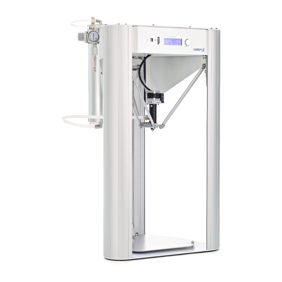
Description of the printer 2 DESCRIPTION OF THE PRINTER The device described in this manual is a 3D printer suitable for 3D printing with the use of filament in thermoplastic material. The printer consists of an heated extruder mounted on a Delta-robot structure, a bed of work and a group of spools. -
Page 16: Control Panel
2.1. Control panel Fig. 2.1 - Control panel Legend: 1. Ethernet cable door 2. USB door 3. Operator display 4. Display control handle (Rotates left and right and it is clickable) © CSP S.r.l. -
Page 17: Work Area
2.2. Work area Fig. 2.2 - Work area Legend: 1. End-filament sensor 2. Aluminum slider 3. Suspended driver 5. Support arm 6. Teflon pipe 7. Extruder © CSP S.r.l. -
Page 18: External Area Of The Printer
2.3. External area of the printer Fig. 2.3 - External area of the printer Legend: 1. CE label 2. Supply © CSP S.r.l. -
Page 19: Technical Data
2.4. Technical data All WASP 3D printers are characterized by considerable strength and working precision. Their mechanics allows for greater precision and stability, guaranteeing greater production speeds. The heated surface and the complete printer’s casing facilitate a homogeneous and constant working temperature. -
Page 20: Noisiness
2.5. Noisiness The noise emitted by the printer only is inferior than 70 dB(A). The presence of more machines in the same area increases the noise. ATTENTION: It is responsibility of the customer to carry out an assessment to reduce the noise risk of his activity as prescribed by the legislation in force in the place where the printer is installed, and to equip the operators with adequate Personal Protective Equipment (such as headphones for hearing protection). -
Page 21: Transport And Handling
Transport and handling 3 TRANSPORT AND HANDLING 3.1. General warnings The reading of this chapter assumes, in order to use the printer safely, the knowledge of the contents of paragraph 1.6 “General safety warnings”. Furthermore, the specific requirements for safe interaction with the printer, related to this chapter, are detailed in the following paragraphs. -
Page 22: Unpackaging
3.2. Unpackaging ENVIRONMENTAL NOTE: Once the packaging has been removed from the printer it is recommended to keep it for any requests for assistance from the Manufacturer. The printer will be delivered in a horizontally oriented wooden box. After removing the printer from the case, you must place the printer upright. NOTE: To perform this procedure it is required the presence of three operators because two of them will take care of overturning it and the other one will keep it steady on one side. -
Page 23: Installation
Installation 4 INSTALLATION 4.1. General warnings The reading of this chapter assumes, in order to use the printer safely, the knowledge of the contents of paragraph 1.6 “General safety warnings”. Furthermore, the specific requirements for safe interaction with the printer, related to this chapter, are detailed in the following paragraphs. -
Page 24: Electrical Connection
4.2. Electrical connection ATTENTION: The operations related to these activities must be performed by authorized and professionally qualified personnel. ATTENTION: It is up to the user to protect the cable mechanically against any crushing or sources of wear according to the type of installation made. ATTENTION: The printer must be powered by a 10A socket protected by a magnetothermic set at 30 mA. -
Page 25: Preparing To Use The Printer
Preparing to use the printer 5 PREPARING TO USE THE PRINTER 5.1. General warnings The reading of this chapter assumes, in order to use the printer safely, the knowledge of the contents of paragraph 1.6 “General safety warnings”. Furthermore, the specific requirements for safe interaction with the printer, related to this chapter, are detailed in the following paragraphs. -
Page 26: User Interface
5.2. User interface 5.2.1. Main board Fig. 5.2.1 - Main board The main board appears when turning on the printer and when launching the print. It is the principal tool for the monitoring and control of the printer Legend: 1. Extruder temperature (clicking it can be modified) 2. -
Page 27: Print Menu
5.2.2. PRINT Menu Fig. 5.2.2 - PRINT Menu PRINT menu contains several commands in order of use that guide you to the launch of the print. Legend: 1. Auto home: puts the machine in position of zeroing of the axes 2. -
Page 28: Prepare Menu
5.2.3. PREPARE menu Fig. 5.2.3 - Menu PREPARE Access clicking it in the toolbar, contains useful tools to be used sometimes. Legend: • Free Zeta system: enters in Free Zeta System (par 8.9) • Set Z max: allows to set a new height for the machine (par 8.10) •... -
Page 29: Advanced Menu
5.2.4. ADVANCED menu Fig. 5.2.4 - Menu ADVANCED Access clicking it in the toolbar, contain tools and settings to be used extraordinarely. Legend: • Send arbitrary command: contains a keyboard to launch commands directly to the board • Wifi settings: to connect the machine to the wifi nerwork (par 8.14) •... -
Page 30: Wifi Settings
5.2.5. WIFI settings Fig. 5.2.5 - WIFI settings With WIFI settings (into the ADVANCED menu) is possible to connect the machine to wifi network (par 8.14). Legend: 1. SSID: to chose the desidered network between all the visible ones 2. PWD: Allows to insert a password, if present 3. -
Page 31: Gcode
5.2.6. GCODE Fig. 5.2.6 - GCODE From PRINT menu, by chosing GCODE you can launch gcodes and move them from the USB to the printer (par 8.5). Legend: 1. Chose USB Drive/Printer Drive 2. Gcode list (the ones on the drive present and icon beside the name) 3. -
Page 32: Info Menu
5.2.7. INFO menu INFO contains useful video tutorials for basic and advanced operations. You can access anytime you want and as you exit videos are paused. Also if you access from specific pages it already directs you to the relative video. ©... -
Page 33: First Start
5.3. First start After having correctly connected the printer to the socket it is necessary to perform some operations in order to allow the printer to work. Belt-stop clamps Inside the printer there are three belts necessary for moving the extruder during printing. To avoid the extruder’s movements during transport, clamps are applied on the straps, to be removed before starting the printer. - Page 34 © CSP S.r.l.
-
Page 35: First Use Of The Printer
First use of the printer 6 FIRST USE OF THE PRINTER 6.1. General warnings The reading of this chapter assumes, in order to use the printer safely, the knowledge of the paragraph 1.6 “General safety warnings”’ contents. Furthermore, the specific requirements for safe interaction with the printer, related to this chapter, are detailed in the following paragraphs. -
Page 36: Gcode Creation
First use of the printer 6.2. Gcode creation Make sure that the 3d model follows these bonds: - watertight geometry - correct positioning on the printing bed - exportation in .stl format 6.3. Slicing software The slicing software divides the 3D model into many sections, giving the user the ability to set temperature and print parameters, determining the quality of the printed product and the process’... -
Page 37: Adhesion To The Bed
First use of the printer 6.6. Adhesion to the bed Before each printing it is necessary to put a glue’s layer, supplied with the printer, on the aluminum plate. 6.7. Selecting gcode Select the printing file from: PRINT>GCODE . Printing will start as soon as the printing bed and the extruder reach the pre-set temperatures. 6.8. -
Page 38: Ordinary And Extraordinary Maintanance
Ordinary and extraordinary maintanance 7 ORDINARY AND EXTRAORDINARY MAINTANANCE 7.1. General warnings The reading of this chapter assumes, in order to use the printer safely, the knowledge of the contents of paragraph 1.6 “General safety warnings”. Furthermore, the specific requirements for safe interaction with the printer, related to this chapter, are detailed in the following paragraphs. - Page 39 Ordinary and extraordinary maintanance © CSP S.r.l.
-
Page 40: Ordinary Maintanance
Ordinary and extraordinary maintanance 7.2. Ordinary maintanance Periodic maintenance and correct use are essential factors to ensure the functionality, safe operation and printer’s durability. The maintenance and the required interventions are carried out by the mechanical maintenance technician who must operate in compliance with the safety instructions contained in this manual. ATTENTION: The maintenance operations must be carried out by disconnecting the printer from the power source by unplugging the power plug. -
Page 41: Sliders
Ordinary and extraordinary maintanance 7.2.5. Sliders Check backlash Check that the arm sliders do not have any backlash between them and the sliding aisle, if it is present, contact the manufacturer 7.2.6. Extruder Cleaning In the event that the extruder is clogged, it is possible to clean it using the appropriate cleaning kit. To clean the extruder consult the material on the website www.3dwasp.com or, for additional informations, contact our support at support@3dwasp.com. -
Page 42: Print Bed Cleaning
Ordinary and extraordinary maintanance 7.2.8. Print bed cleaning The bed could be cleaned with the machine switched off. It is necessary in cases of: • Flatness compromised • Dirt that prevents adhesion during printing • Aesthetic necessity To carry out this operation it is necessary to remove the top by unscrewing the three screws indicated in figure 7.2. -
Page 43: Extraordinary Maintenance
Ordinary and extraordinary maintanance 7.3. Extraordinary maintenance ATTENTION: Extraordinary maintenance operations must be carried out by the Manufacturer’s Technicians or by maintenance personnel who have been instructed and authorized by the Manufacturer. Any of these operations not carried out by a manufacturer’s technician can cause irreversible damage to the machine or its parts and therefore would null and void the warranty. -
Page 44: Cartridge Removal
Ordinary and extraordinary maintanance 7.3.1. Cartridge removal The cartridge change is a mechanical operation that allows you to change the cartridge with another in the same extruder. Thanks to the cartridge’s change it is possible to characterize the extruder with nozzles of different diameters and rods for high temperatures. - Page 45 Ordinary and extraordinary maintanance fig 7.3.1 a fig 7.3.1 b fig 7.3.1 c fig 7.3.1 d © CSP S.r.l.
-
Page 46: Remove The Cartridge With Zen Extruder
Ordinary and extraordinary maintanance 7.3.2. REMOVE THE CARTRIDGE WITH ZEN EXTRUDER • With the extruder correctly connected, turn the machine on. • Bring the extruder to the loaded material’s minimum print temperature (eg PLA 180 - ABS 220 ° C) and wait a few seconds •... - Page 47 Ordinary and extraordinary maintanance fig 7.3.1 a fig 7.3.1 b fig 7.3.1 c fig 7.3.1 d © CSP S.r.l.
-
Page 48: Manual Leveling
Ordinary and extraordinary maintanance 7.3.3. Manual leveling Manual leveling is a command that allows you to adjust the planarity of the aluminum bed. Based on the three-point principle, the machine moves the tool to the vertices of an equilateral triangle proportional to the aluminum bed. - Page 49 Ordinary and extraordinary maintanance fig 7.3.4 a fig 7.3.4 b fig 7.3.4 c fig 7.3.4 d © CSP S.r.l.
-
Page 50: Flex Extruder Cleaning
Ordinary and extraordinary maintanance 7.3.5. Flex extruder cleaning It is necessary when the extruder is clogged, ie it does not extrude or has an unusually low and non-homogeneous flow during the extrusion. To properly clean the Flex extruder: • Remove the teflon protection around the heating block by removing the screw with a 3mm Allen wrench •... - Page 51 Ordinary and extraordinary maintanance fig 7.3.4 a fig 7.3.4 b fig 7.3.4 c fig 7.3.4 d © CSP S.r.l.
-
Page 52: Use Of The Printer
Use of the printer 8 USE OF THE PRINTER 8.1. Adhesion to the bed The adhesion to the printing bed takes place during the deposition of the first layer and is essential for the success of the printing. The fundamental points of a good adhesion are: •... - Page 53 Use of the printer © CSP S.r.l.
-
Page 54: Zen Extruder Calibration
Use of the printer 8.3. Zen extruder calibration The Zen extruder is composed of two extrusion modules to allow multi-color and multi-material prints. It could happen that the two extruders are not calibrated to each other. In the case of the Zen extruder, calibration requires, in addition to the normal calibration (plane leveling and height modification), an offset setting procedure between the two tilting nozzles. - Page 55 Use of the printer -5 -4 -3 -2 - 1 1 2 3 4 5 Fig. 8.3a- Explaining of calibration grid -5 -4 -3 -2 - 1 1 2 3 4 5 Fig. 8.3b- Example of non correct calibration grid -5 -4 -3 -2 - 1 1 2 3 4 5 Fig.
-
Page 56: Load Filament
Use of the printer 8.4. Load filament To load the filament proceed as follows: 1. Place the spool on its support. In case of a single extruder use the left support. 2. Lead the filament inside the machine making sure to pass it through the end-filament sensor. 3. - Page 57 Use of the printer fig 8.4 a fig 8.4 b fig 8.4 c fig 8.4 d Fig. 8.5- Manual filament loading © CSP S.r.l.
-
Page 58: Load .Gcode
Use of the printer 8.5. Load .gcode In the WASP 4.0 line the gcode can be loaded in two ways: • Using a USB pendrive • Using the Wi-fi module 8.5.1. Loading with pendrive USB 1. Correctly save the file in .gcode format on the pendrive. - Page 59 Use of the printer Fig. 8.5.1- Gcode loaded with USB drive (notice icon beside the file name) Fig. 8.5.2 - Gcode wifi loaded with Octoprint © CSP S.r.l.
-
Page 60: Continuous Printing
Use of the printer 8.6. Continuous printing Continuous printing is an option to print in sequence with the two nozzles. The printing starts with the left extruder and as soon as the end-filament sensor of the first nozzle realizes that it is without material, it switches the second nozzle which continues processing, conserving temperatures and settings. - Page 61 Use of the printer fig. 8.7- Delete gcode from machine © CSP S.r.l.
-
Page 62: Manual Extrusion
Use of the printer 8.8. Manual extrusion Manual extrusion is an operation that is carried out when the machine is stopped, to verify that the plastic outlet is homogeneous. To do this it is necessary to take the nozzle to the print temperature of the plastic you are working with. The procedure is this: 1. - Page 63 Use of the printer fig. 8.8a - “Manual extrusion” command (inside PREPARE menu) Fig. 8.8b - Manual filament loading © CSP S.r.l.
-
Page 64: Free Zeta System
Use of the printer 8.9. Free zeta system The Free Zeta system is a useful command to resume interrupted prints and for any reason it was not possible to recover with the Resurrection system. It is based on the principle of restarting to print a chosen gcode from a certain height onwards, so that the first layer of the new print adheres to the last printed layer. - Page 65 Use of the printer Fig. 8.9-8.10 - “Free Z System” and “Modify Height” commands inside PREPARE menu fig. 8.9b- “Free Zeta system” command fig. 8.10- “Modify Height” command © CSP S.r.l.
-
Page 66: Change Core
Use of the printer 8.11. Change Core The Multi-core system is a system that simplifies the configuration and use of different types of extruders on the same machine. Among the advantages it brings there are: • Compatibility with Spitfire, Zen and Flex extruders •... - Page 67 Use of the printer fig 8.11 a fig 8.11 b fig 8.11 c fig 8.11 d Fig. 8.11 - Change core - Multi-core © CSP S.r.l.
- Page 68 Use of the printer 7. Fit the new extruder with attention to alignment 8. Reconnect the cables following the colors on the cables and on the extruder 9. Start the autocalibration fig 8.11 e fig 8.11 f © CSP S.r.l.
- Page 69 Use of the printer fig 8.11 g fig 8.11 h fig 8.11 i fig 8.11 l Fig. 8.11- Change core - Multicore © CSP S.r.l.
-
Page 70: Resurrection System
Use of the printer 8.12. Resurrection system The Resurrection system is a command for the automatic recovery of the print jobs interrupted by a sudden switch-off during processing. The system is designed in particular for: Blackouts and sudden power failures during printing Accidental removal of the power cord during printing In addition, it should be considered that in the time span between turning off the machine and launching the “Resurrection”... - Page 71 Use of the printer Fig. 8.13 - Removing the object from the bed © CSP S.r.l.
-
Page 72: Wifi And Remote Control
1. Make sure that both the computer and the printer are connected to the same wifi network 2. Enter in the URL of the browser* the IP address that appears on the machine adding at the bottom “/ wasp” (eg http://192.128.12.114/wasp) 3. - Page 73 Use of the printer Fig. 8.14a- “Octoprint” control environment on browser Fig. 8.14b- “Octoprint” control environment on browser © CSP S.r.l.
-
Page 74: Additional Instructions
Additional instructions 9 ADDITIONAL INSTRUCTIONS 9.1. General warnings The reading of this chapter assumes, in order to use the printer safely, the knowledge of the contents of paragraph 1.6 “General safety warnings”. Furthermore, the specific requirements for safe interaction with the printer, related to this chapter, are detailed in the following paragraphs. -
Page 75: Instructions For Emergency Situations
Additional instructions If the mechanical parts have to be dismantled, keep in mind that they consist of different types of material. The user is therefore obliged to consider disassembling the printer in its parts in order to facilitate a differentiated disposal aimed at recycling the various materials and products, in full compliance with all the regulations in force on the spot. - Page 76 Additional instructions NOTES __________________________________________________________________________________ __________________________________________________________________________________ __________________________________________________________________________________ __________________________________________________________________________________ __________________________________________________________________________________ __________________________________________________________________________________ __________________________________________________________________________________ __________________________________________________________________________________ __________________________________________________________________________________ __________________________________________________________________________________ __________________________________________________________________________________ __________________________________________________________________________________ __________________________________________________________________________________ __________________________________________________________________________________ __________________________________________________________________________________ __________________________________________________________________________________ __________________________________________________________________________________ __________________________________________________________________________________ __________________________________________________________________________________ __________________________________________________________________________________ __________________________________________________________________________________ __________________________________________________________________________________ __________________________________________________________________________________ __________________________________________________________________________________ __________________________________________________________________________________ __________________________________________________________________________________ __________________________________________________________________________________ © CSP S.r.l.
- Page 77 Additional instructions __________________________________________________________________________________ __________________________________________________________________________________ __________________________________________________________________________________ __________________________________________________________________________________ __________________________________________________________________________________ __________________________________________________________________________________ __________________________________________________________________________________ __________________________________________________________________________________ __________________________________________________________________________________ __________________________________________________________________________________ __________________________________________________________________________________ __________________________________________________________________________________ __________________________________________________________________________________ __________________________________________________________________________________ __________________________________________________________________________________ __________________________________________________________________________________ __________________________________________________________________________________ __________________________________________________________________________________ __________________________________________________________________________________ __________________________________________________________________________________ __________________________________________________________________________________ __________________________________________________________________________________ __________________________________________________________________________________ © CSP S.r.l.
- Page 78 Additional instructions © CSP S.r.l.
- Page 79 CSP S.R.L. Viale Zaganelli, 26 - 48024 Massa Lombarda (RA) Italia Tel. +39 0545 82966 www.wasproject.it - info@wasproject.it...
Need help?
Do you have a question about the Delta Wasp 2040 Industrial 4.0 and is the answer not in the manual?
Questions and answers