
Related Manuals for emaux ICF100


Summary of Contents for emaux ICF100
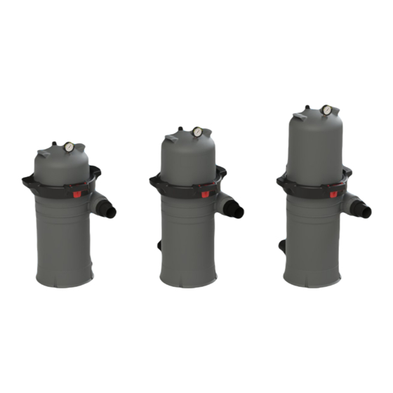
- Page 1 SINGLE ELEMENT CARTRIDGE FILTER Installation and Operation USER MANUAL Models: ICF100 / ICF150 ICF200 EMFI22050602...
-
Page 2: Table Of Contents
TABLE OF CONTENT ..IMPORTANT SAFETY INSTRUCTIONS 1. OVERVIEW ..1.1 PRODUCT INFORMATION 1.2 DIMENSIONS ..2. INSTALLATION ..3. STARTING THE PUMP AND FILTER SYSTEM 3.1 BEFORE STARTING THE PUMP 3.2 STARTING PUMP 3.3 OPERATION 4. MAINTAINING YOUR FILTER .. -
Page 3: Important Safety Instructions
IMPORTANT SAFETY INSTRUCTIONS THESE OPERATING INSTRUCTIONS CONTAIN IMPORTANT INFORMATION ON THE SAFE, PROPER, AND ECONOMICAL OPERATION OF THIS SWIMMING POOL APPLIANCE. STRICT OBSERVATION OF THE OPERATING INSTRUCTIONS WILL HELP TO AVOID DANGERS, REDUCE REPAIR COSTS, AND SHUTDOWN TIMES AND INCREASE THE RELIABILITY AND WORKING LIFE OF THE PRODUCT. Failure to follow the instructions in this manual may result in serious adverse health effects or even serious or fatal injury. -
Page 4: Overview
READ UNDERSTAND AND FOLLOW ALL SAFETY AND OPERATION: Do not operate the filter until you have read and understand clearly all the operating instructions and warning messages for all equipment that is a part of the pool circulating system. The following instructions are intended as a guide for initially operating the filter in a general pool installation. -
Page 5: Product Information
EFFECTIVE FITRATION DESIGN FLOW RATE CODE Model AREA Residential Commercial FT² M² 9140401 ICF100 9.29 9140402 ICF150 13.94 9140403 ICF200 18.58 ≤ ≤ [ Filter rate for residential use based on 1GPM/ft². Recommend Flow Rate for 2” piping is 90 x 150 GPM ] 1.2 DIMENSIONS... -
Page 6: Starting The Pump And Filter System
3. STARTING THE PUMP AND FILTER SYSTEM 3.1 BEFORE STARTING THE PUMP 1. Use ONLY ICF system components: Lock Ring unit doing assembly, metal-reinforced seal. Non-tighten lock ring component may fail in use and cause explosive component separation. Verify that upper and lower filter bodies are properly secured with the filter body locking ring unit. -
Page 7: Operation
3.3 OPERATION Filtration starts as soon as the flow is steady through the filter. As the filter removes dirt from the pool water, the accumulated dirt causes a resistance to flow. As a result, the pressure will rise and the flow will decrease. 1. -
Page 8: Clean Seal Ring And Seal Surface
1. Place the sealing O-ring on the bottom body. Place the upper body on the O-ring and the bottom body. 2. Use the EMAUX lock ring system only, tighten the lock ring (clockwise) until the latch is locked on position. -
Page 9: Removing The Air Relief Valve
4.5 REMOVING THE AIR RELIEF VALVE The filter comes with a preinstalled manual air relief valve. Ser vicing the Air Relief Valve should be carried out by pool professionals only, follow instructions carefully: 1. Turn off all system circulation pumps and all-electric power on the equipment pad. 2. -
Page 10: Spare Part List
Nut D31X20 14G 914100004 ICF100 Element 914100005 ICF150 Element 914100006 ICF200 Element 107048520 PVC Pipe 2.5inch for ICF100, 387 mm 107048520 PVC Pipe 2.5inch for ICF150, 440mm 107048520 PVC Pipe 2.5inch for ICF200, 517mm 550128166 ICF100-200 Center Drain connection SPARE PART LIST... -
Page 11: Terms Of The Warranty
It excludes all expendable parts. During the warranty period, Emaux authorized reseller will repair or replace defective parts with new parts or, at the option of Emaux, serviceable used parts that are equivalent or superior to new parts in performance. - Page 12 EMAUX WATER TECHNOLOGY CO., LTD YOUR PREMIER SUPPLIER www.emauxgroup.com...
Need help?
Do you have a question about the ICF100 and is the answer not in the manual?
Questions and answers