Advertisement
Available languages
Available languages
Quick Links
20-25minutes
approx assembly time
THIS INSTRUCTION BOOKLET CONTAINS IMPORTANT SAFETY INFORMATION.
PLEASE READ AND KEEP FOR FUTURE REFERENCE.
For assistance with assembly or installation, parts and customer
service , call 1-888-568-3818 Monday-Friday 8:30am-5:30pm
PST (U.S)
Email: customerservice.s@goldenspecies.com
Working hour: Mon.-Fri., 8:30am - 5:30pm Pacific Standard
Time.
Stock # GSB332198-2
Lot Number : _________
Date Purchased ______/____/_____
Manufactured By : Young Chain Company Limited
Binh Duong Province, Vietnam
TEL : 1-888-568-3818
EMAIL : customerservice.s@goldenspecies.com
TM
Two adults
Assembly required
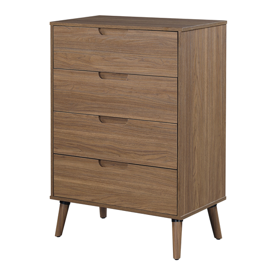
Modern 4 Drawer Dresser
Stock # GSB332198-2
MAXIMUM LOAD 44 LB (20 KG)
DRAWER MAXIMUM LOAD
10 LB (4.54 KG)
Review your purchases, thank you!
Share your feedback to help other shoppers
Link for this product is as below:
www.walmart.com/ip/605755137
We are available to assist you Monday-Friday
From 8:30am-5:30pm PST (US)
MAINSTAYS
Advertisement

Related Manuals for Mainstays Modern GSB332198-2


Summary of Contents for Mainstays Modern GSB332198-2
- Page 1 MAINSTAYS Modern 4 Drawer Dresser Stock # GSB332198-2 MAXIMUM LOAD 44 LB (20 KG) 20-25minutes Two adults approx assembly time Assembly required DRAWER MAXIMUM LOAD 10 LB (4.54 KG) THIS INSTRUCTION BOOKLET CONTAINS IMPORTANT SAFETY INFORMATION. PLEASE READ AND KEEP FOR FUTURE REFERENCE.
- Page 2 MAINSTAYS Modern 4 Drawer Dresser Stock # GSB332198-2 Important Safety Information Please read all instructions carefully before assembling this furniture. For your safety, assembly by two or more adults is strongly recommended. Use only vendor-supplied hardware to assemble this item. Using unauthorized hardware could jeopardize the structural integrity of the item.
- Page 3 PARTS BASE SIDE PANEL BACK PANEL ×1 ×1 ×2 ×1 MIDDLE BAR SIDE LEG DRAWER FRONT DRAWER LEFT ×1 ×4 PANEL ×4 PANEL ×4 DRAWER RIGHT DRAWER BACK DRAWER BOTTOM SUPPORT BAR PANEL ×4 PANEL ×4 PANEL ×4 ×4 VERIFY THAT ALL PARTS ARE LISTED BEFORE BEGINNING Page 3...
- Page 4 HARDWARE LIST CAM BOLT CAM LOCK DOWEL BUCKLE ×44+1 ×44+1 ×20+1 ×8 SHORT ROUND FLAT HEAD STICKER PVC LONG ROUND HEAD SCREW SCREW ×24+1 ×16+1 HEAD SCREW ×16+1 ×16+1 TOOLS NEEDED FOR ASSEMBLY (NOT PROVIDED) Anti-tip Hardware BRACKET ANTI-TIP CABLE LONG SCREW SHORT SCREW PLASTIC ANCHOR...
- Page 5 CAM FASTEN SYSTEM EXAMPLE RING SHOULD TOUCH THE BOARD Screw the cam bolt into the predrilled panel. The cam bolt should be tightened so no threads are visible. The larger ring of the cam should touch the panel. Insert the cam lock into the predrilled hole in the panel. Arrow faces the outside of the panel.
- Page 6 ASSEMBLY Place the TOP ( A ) face down on a smooth soft surface. The side with the holes should be facing up. Insert the CAM BOLT ( 1 ) into the corresponding hole of the TOP ( A ). And use a hand screwdriver to tighten the CAM BOLT ( 1 ) clockwise.
- Page 7 ASSEMBLY Place the SIDE PANEL ( C ) face down on a smooth soft surface. The side with the holes and glides should be facing up. Insert the CAM BOLT ( 1 ) into the corresponding hole of the SIDE PANEL ( C ). And use a hand screwdriver to tighten the CAM BOLT ( 1 ) clockwise.
- Page 8 ASSEMBLY Insert the DOWEL ( 3 ) all the way into the corresponding hole of the SIDE PANEL ( C ). Repeat these same steps for another ( C ). SIDE PANEL DOWEL ×8 Please call for replacement parts or assistance: 1-888-568-3818 Young Chain Company Limited Page 8...
- Page 9 ASSEMBLY Insert the DOWEL ( 3 ) all the way into the corresponding hole of the BACK PANEL ( D ). DOWEL ×8 Please call for replacement parts or assistance: 1-888-568-3818 Young Chain Company Limited Page 9...
- Page 10 ASSEMBLY Align the corresponding hole of the BACK PANEL ( D ) and SIDE PANEL ( C ) as figure shown below. Insert the CAM LOCK ( 2 ) into the corresponding hole ( the direction of the notch is aligned with the cam bolt as the figure shown below).
- Page 11 ASSEMBLY Align the corresponding hole of the MIDDLE BAR ( E ) and SIDE PANEL ( C ) as figure shown below. Align the corresponding hole of the MIDDLE BAR ( E ) and BACK PANEL ( D ) into the corresponding holes of SIDE PANEL ( C ) as figure shown below .
- Page 12 ASSEMBLY Insert the SIDE PANEL( C ) & BACK PANEL ( D ) into the corresponding hole of TOP ( A ). Place the CAM LOCK ( 2 ) into the corresponding hole ( the direction of the notch of the cam locks align with the cam bolt ). Use a hand screwdriver to turn the CAM LOCK ( 2 ) clockwise to secure the cam bolt.
- Page 13 ASSEMBLY Insert the SIDE PANEL ( C ) & BACK PANEL ( D ) into the corresponding hole of the BASE ( B ). Place the CAM LOCK ( 2 ) into the corresponding hole ( the direction of the notch of the cam locks align with the cam bolt ).
- Page 14 ASSEMBLY Use LONG ROUND HEAD SCREW ( 8 ) to attach the LEG ( F ) to the pilot holes on BASE ( B ). Repeat these steps for all the four legs. Note: Use the adjustable levelers to level the if needed.
- Page 15 ASSEMBLY Place the DRAWER FRONT PANEL ( G ), DRAWER LEFT PANEL ( H ), DRAWER RIGHT PANEL ( I ) and DRAWER BACK PANEL ( J ) face down on a smooth soft surface. The side with the holes should be facing up. Insert the CAM BOLT ( 1 ) into the corresponding hole of DRAWER FRONT PANEL ( G ) as shown in below figures.
- Page 16 ASSEMBLY Insert the DOWEL ( 3 ) all the way into the corresponding hole of the SUPPORT BAR ( L ). Repeat all steps for all 4 drawers. DOWEL ×4 Please call for replacement parts or assistance: 1-888-568-3818 Young Chain Company Limited Page 16...
- Page 17 ASSEMBLY Align and insert the DRAWER LEFT PANEL ( H ) and DRAWER RIGHT PANEL ( I ) into the corresponding hole of DRAWER FRONT PANEL ( G ). Align and insert the SUPPORT BAR ( L ) into the corresponding hole of DRAWER FRONT PANEL ( G ).
- Page 18 ASSEMBLY Align and insert the DRAWER BOTTOM PANEL ( K ) to the groove of DRAWER LEFT PANEL ( H ) and DRAWER RIGHT PANEL ( I ). All the way until into the groove of the DRAWER FRONT PANEL ( G ). Repeat all steps for all 4 drawers.
- Page 19 ASSEMBLY Insert the DRAWER BACK PANEL ( J ) into the corresponding groove of the assembled drawer box. Place the ( 6 ) into the corresponding hole. FLAT HEAD SCREW Use a hand screwdriver to turn the ( 6 ) clockwise to secure the FLAT HEAD SCREW Drawer back panel Repeat all steps for all 4 drawers.
- Page 20 ASSEMBLY Attach the BUCKLE ( 4 ) to the corners formed under the bottom of drawer assembly by using the ( 5 ). See figure shown below. SHORT ROUND HEAD SCREW Cover any visible CAM LOCK ( 2 ) using STICKER ( 7 ) as shown below. ** Repeat all steps for all 4 drawers.
- Page 21 ASSEMBLY Turn the assembled dresser upright as shown in the figure below. Pull out the drawer glides on the side panels all the way and move ball bearing pieces to the front ends, as figure shown below. Insert the pre-assembled glides on the drawer side panels into the glides on the side panel and push in to assemble the drawer.
- Page 22 ASSEMBLY FIG.1 Attach the BRACKET to the BACK PANEL by using the SHORT SCREW Tighten it by the BRACKET screwdriver. SHORT SCREW FIG.2 WALL LONG SCREW ANTI-TIP CABLE FIG.2A FIG.2B Use power-drill Press the PLASTIC to drill holes on ANCHOR the wall.
- Page 23 MAINSTAYS Cómoda moderna de 4 cajones Valores # GSB332198-2 20-25 minutos Dos adultos CARGA MÁXIMA 44 LB (20 KG) tiempo aproximado se requiere de montaje ensamblaje CARGA MÁXIMA DEL CAJÓN 10 LB (4.54 KG) ESTE FOLLETO DE INSTRUCCIONES CONTIENE INFORMACIÓN IMPORTANTE DE SEGURIDAD.
- Page 24 MAINSTAYS Cómoda moderna de 4 cajones Valores # GSB332198-2 Informacion de Seguridad Importante Lea atentamente todas las instrucciones antes de montar este mueble. Por su seguridad, se recomienda encarecidamente el montaje por dos o más adultos. Utilice únicamente hardware proporcionado por el proveedor para ensamblar este artículo.
- Page 25 PARTES PANEL CIMA BASE PANEL LATERAL POSTERIOR ×1 ×1 ×2 ×1 PANEL FRONTAL PANEL IZQUIERDO BARRA MEDIA PIERNA ×1 LATERAL ×4 DEL CAJÓN × 4 DEL CAJÓN × 4 PANEL DERECHO PANEL TRASERO PANEL INFERIOR BARRA DE SOPORTE ×4 DEL CAJÓN × 4 DEL CAJÓN ×...
- Page 26 LISTA DE HARDWARE CLAVIJA HEBILLA PERNO BLOQUEO ×8 DE LEVA DE LEVA ×20+1 ×44+1 ×44+1 REDONDA CABEZA PLANA PEGATINA PVC RONDA LARGA CORTA TORNILLO TORNILLO ×24+1 ×16+1 TORNILLO DE DE CABEZA CABEZA ×16+1 ×16+1 HERRAMIENTAS NECESARIAS PARA EL MONTAJE (NO SUMINISTRADAS) Hardware antivuelco ANCLA SOPORTE...
- Page 27 EJEMPLO DE SISTEMA DE FIJACIÓN DE LEVA EL ANILLO DEBE TOCAR EL TABLERO Atornille el perno de leva en el panel perforado previamente. El perno de la leva debe apretarse para que no se vean las roscas. El anillo más grande de la leva debe tocar el panel. Inserte el seguro de leva en el orificio pretaladrado en el panel.
- Page 28 MONTAJE Coloque la CIMA ( A ) boca abajo sobre una superficie suave y lisa. El lado con los agujeros debe mirar hacia arriba. Inserte el PERNO DE LEVA ( 1 ) en el orificio correspondiente de la CIMA ( A ). Y use un destornillador de mano para apretar el PERNO DE LEVA ( 1 ) en el sentido de las agujas del reloj.
- Page 29 MONTAJE Coloque el PANEL LATERAL ( C ) boca abajo sobre una superficie suave y lisa. El lado con los agujeros y los deslizadores debe estar hacia arriba. Inserte el PERNO DE LEVA ( 1 ) en el orificio correspondiente del PANEL LATERAL ( C ). Y use un destornillador de mano para apretar el PERNO DE LEVA ( 1 ) en el sentido de las agujas del reloj.
- Page 30 MONTAJE Inserte la ( 3 ) hasta el fondo en el orificio correspondiente del PANEL LATERAL CLAVIJA ( C ). ** Repita estos mismos pasos para otro PANEL LATERAL ( C ). CLAVIJA ×8 Llame para solicitar piezas de repuesto o asistencia: 1-888-568-3818 Young Chain Company Limited Página 8...
- Page 31 MONTAJE Inserte la CLAVIJA ( 3 ) hasta el fondo en el orificio correspondiente del PANEL ( D ). POSTERIOR CLAVIJA ×8 Llame para solicitar piezas de repuesto o asistencia: 1-888-568-3818 Young Chain Company Limited Página 9...
- Page 32 MONTAJE Alinee el orificio correspondiente del PANEL POSTERIOR ( D ) y el PANEL LATERAL ( C ) como se muestra a continuación. Inserte el BLOQUEO DE LEVA ( 2 ) en el orificio correspondiente ( la dirección de la muesca está...
- Page 33 MONTAJE Alinee el orificio correspondiente de la BARRA MEDIA ( E ) y el PANEL LATERAL ( C ) como se muestra a continuación. Alinee el orificio correspondiente de la BARRA MEDIA ( E ) y el PANEL POSTERIOR ( D ) en los orificios correspondientes del PANEL LATERAL ( C ) como se muestra en la figura a continuación.
- Page 34 MONTAJE Inserte el PANEL LATERAL ( C ) y el PANEL POSTERIOR ( D ) en el orificio correspondiente de la CIMA ( A ). Coloque el BLOQUEO DE LEVA ( 2 ) en el orificio correspondiente ( la dirección de la muesca de los bloqueos de leva se alinea con el perno de leva ).
- Page 35 MONTAJE Inserte el PANEL LATERAL ( C ) y el PANEL POSTERIOR ( D ) en el orificio correspondiente de la BASE ( B ). Coloque el BLOQUEO DE LEVA ( 2 ) en el orificio correspondiente ( la dirección de la muesca de los bloqueos de leva se alinea con el perno de leva ).
- Page 36 MONTAJE Utilice un ( 8 ) para sujetar la RONDA LARGA TORNILLO DE CABEZA PIERNA LATERAL ( F ) a los orificios guía de la BASE ( B ). ** Repita estos pasos para las cuatro patas. Nota: Utilice los niveladores ajustables para nivelar la cómoda moderna de 4 cajones si es necesario.
- Page 37 MONTAJE MONTAJE Coloque el PANEL FRONTAL DEL CAJÓN ( G ), el PANEL IZQUIERDO DEL CAJÓN ( H ), el PANEL DERECHO DEL CAJÓN ( I ) y el PANEL TRASERO DEL CAJÓN ( J ) boca abajo sobre una superficie suave y lisa. El lado con los agujeros debe estar hacia arriba. Inserte el PERNO DE LEVA ( 1 ) en el orificio correspondiente del PANEL FRONTAL DEL CAJÓN ( G ) como se muestra en las figuras siguientes.
- Page 38 MONTAJE Inserte la ( 3 ) hasta el fondo en el orificio correspondiente de la BARRA DE CLAVIJA SOPORTE ( L ). ** Repita todos los pasos para los 4 cajones. CLAVIJA ×4 Llame para solicitar piezas de repuesto o asistencia: 1-888-568-3818 Young Chain Company Limited Página 16...
- Page 39 MONTAJE Alinee e inserte el PANEL IZQUIERDO DEL CAJÓN ( H ) y el PANEL DERECHO DEL CAJÓN ( I ) en el orificio correspondiente del PANEL FRONTAL DEL CAJÓN ( G ). Alinee e inserte la BARRA DEL SOPORTE ( L ) en el orificio correspondiente del PANEL FRONTAL DEL CAJÓN ( G ).
- Page 40 MONTAJE Alinee e inserte el PANEL INFERIOR DEL CAJÓN ( K ) en la ranura del PANEL IZQUIERDO DEL CAJÓN ( H ) y el PANEL DERECHO DEL CAJÓN ( I ). Todo el camino hasta la ranura del PANEL FRONTAL DEL CAJÓN ( G ). Repita todos los pasos para los 4 cajones.
- Page 41 MONTAJE Inserte el PANEL TRASERO DEL CAJÓN ( J ) en la ranura correspondiente de la caja del cajón ensamblada. Coloque el ( 6 ) en el orificio correspondiente. CABEZA PLANA TORNILLO Utilice un destornillador de mano para girar el ( 6 ) en el CABEZA PLANA TORNILLO sentido de las agujas del reloj para asegurar el panel posterior del cajón.
- Page 42 MONTAJE Fije la HEBILLA ( 4 ) a las esquinas formadas debajo de la parte inferior del ensamblaje del cajón usando el ( 5 ). REDONDA CORTA TORNILLO DE CABEZA Consulte la figura que se muestra a continuación. Cubra cualquier BLOQUEO DE LEVA visible ( 2 ) usando la ( 7 ) como PEGATINA PVC se muestra a continuación.
- Page 43 MONTAJE Coloque la cómoda ensamblada en posición vertical como se muestra en la figura siguiente. Extraiga completamente las guías del cajón en los paneles laterales y mueva las piezas del rodamiento de bolas hacia los extremos frontales, como se muestra en la figura a continuación.
- Page 44 MONTAJE FIG.1 Fije el SOPORTE al PANEL TRASERO usando el TORNILLO CORTO Apretarlo con el SOPORTE destornillador. TORNILLO CORTO PARED FIG.2 Pared TORNILLO LARGO PARED CABLE ANTI VUELTA FIG.2B FIG.2A Presione el ANCLA Use un taladro DE PLÁSTICO eléctrico para firmemente a mano.
Need help?
Do you have a question about the Modern GSB332198-2 and is the answer not in the manual?
Questions and answers