Table of Contents
Advertisement
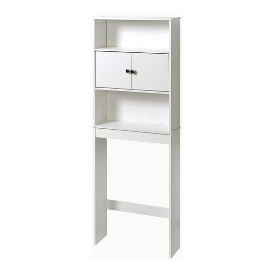
Assembly Instructions
Model 9409WWWM (White)
Para instrucciones en español y francés, comience en la página 20.
Pour les instructions espagnoles et françaises, commencez à la page 20.
Before You Begin:
Thank you for purchasing this product. Please identify all parts and hardware
pieces before you begin. When laying out parts, place them on a soft surface
to prevent scratching.
If any pieces are missing, call our Toll Free Number 1-800-892-3986 between
8:00AM-5:00PM EST Monday through Friday.
Pg 1 of 38
For Spanish and French instructions, start on page 20.
support rail (F)
location for
front or back
MCS 6/03/2019
1-800-892-3986
IS9949
Advertisement
Table of Contents

Related Manuals for Mainstays 9409WWWM


Summary of Contents for Mainstays 9409WWWM
- Page 1 Assembly Instructions Model 9409WWWM (White) For Spanish and French instructions, start on page 20. Para instrucciones en español y francés, comience en la página 20. Pour les instructions espagnoles et françaises, commencez à la page 20. support rail (F) location for...
- Page 2 Cleaning Note: Cleaning with a dry cloth may be sufficient, but for other stains or marks wipe gently with a damp cloth. DO NOT use strong detergents or abrasive cleaners, they may damage the surface of this product It is imperative that the unit be fastened to the wall for safety and stability.
- Page 3 List of Parts three holes at the bottom Top and Bottom Shelf Back Panel Fixed Shelf Support Rail / Trim Top Side Panel ( C-R right and C-L left) Bottom Side Panel Door Optional Leg Extension Pg 3 of 38 1-800-892-3986 IS9949...
- Page 4 List of Hardware Allen Wrench for use with Large Screws (H2) Large Screw x 24 Nail x 40 Cambolt Plastic Snap Cam Hinge Bushing Hinge Hinge Screw Magnet Magnet Screw H 10 Pg 4 of 38 1-800-892-3986 IS9949...
- Page 5 List of Hardware - continued H 11 Knob Knob Screw H 12 Magnet Strike H 13 Magnet Strike Screw H 14 x 16 Screw Cap H 15 Sheet of 6 stickers H 16 Wall Mount Kit Anti-tip Screw Washer Nylon Strap Pg 5 of 38 1-800-892-3986 IS9949...
- Page 6 Leg Extensions - Option A adds 3 in. • NOTE: The closed end faces out. • Insert the bottom side panels (G) into the middle channel, making sure the space saver is completely aligned with the leg extensions. NOTE: If needed, lightly tap the leg extension with a rubber mallet to install. Closed end towards front back of...
- Page 7 Step 1 - Leg Assembly. • Fasten ONE support rail (F) to bottom side panels (G). This is the bottom assembly. NOTE: Support rail (F) can be fastened in the back location according to your preference. unfinished edge facing up unfinished edge facing up back of...
- Page 8 Step 2 - Attaching the Lower Support Rail. • Place the bottom assembly in the desired location. NOTE: If the unit does not fit around your toilet to your satisfaction, you can add the leg extensions (H). • Install the other support rail (F) with the unfinished edge facing down. Unfinished edge of the support rail (F) faces down.
- Page 9 !! SELECT DOOR LOCATION !! STOP Fig. 2 Fig. 1 For doors located in the TOP, For doors (D) located at the MIDDLE, go to step 3.1-TOP, page 11. go to step 3.1-MIDDLE, page 10. Pg 9 of 38 1-800-892-3986 IS9949...
- Page 10 Step 3.1-MIDDLE - Cabinet Assembly for MIDDLE DOOR installation option. • NOTE: Do NOT fully tighten side panels (C-L and C-R) to the fixed shelves (B). Magnet holes facing DOWN on the fixed shelf (B). finished edge Three holes at the Magnet holes facing UP BOTTOM.
- Page 11 Step 3-1 - Cabinet Assembly for TOP DOOR installation option. • NOTE: Do NOT fully tighten side panels (C-L and C-R) to the fixed shelves (B). Magnet holes facing UP on fixed shelf (B). finished edge Three holes at the Magnet holes facing DOWN BOTTOM.
- Page 12 Step 4 - Attaching the Bottom Panel. Magnet holes facing DOWN on the bottom shelf (A). Step 5 - Installing the Cambolts. • NOTE: DO NOT OVERTIGHTEN CAMBOLTS (H4)! Pg 12 of 38 1-800-892-3986 IS9949...
- Page 13 Step 6 - Attaching the Back Panel. • Lay the unit face down on floor with the unfinished edges facing up. • Fasten back panel (E) to back of unit. • Helpful Hint: With the seam side of back panel facing up align the back panel properly, fasten a nail in each of the corners of the back panel first.
- Page 14 Step 7 - Attaching the Top assembly to the Bottom assembly. • Carefully place the top assembly onto the bottom assembly. NOTE: Be sure to align the cambolts (H4) with the holes in bottom side panels (G). • Insert snap cams (H5) into the holes in the bottom side panels (G). NOTE: If necessary, lightly tap the snap cams with a hammer.
- Page 15 Step 8 - Installing the TOP Hinges. H 13 H 14 Incorrect!! Correct!! H 14 H 13 unfinished edge unfinished edge Pg 15 of 38 1-800-892-3986 IS9949...
- Page 16 Step 9 - Installing the Magnet. Assembly for TOP DOOR installation option. H 10 RECOMMEND H 10 Pg 16 of 38 1-800-892-3986 IS9949...
- Page 17 Step 10 - Attaching the Doors. • Set the left side door into the top hinge bushing. • Fit bottom hinge (H7) into the bottom hinge bushing and fasten the bottom hinge (H7) to the door (D). • Attach door knob (H11) to the door (D). •...
- Page 18 Step 11 - Attaching Screw Caps. • NOTE: Make sure to FULLY TIGHTEN the large screws (H-2) that connect the side panels (C-L and C-R) to the fixed shelves (B). x 16 H 15 H 16 Apply stickers (H16) to unused holes. FULLY TIGHTEN the large screws (H2) H 15...
- Page 19 Step 12 - Mounting the unit to the wall. RECOMMEND WARNING: BEFORE CUTTING OR DRILLING INTO ANY WALL SURFACE, VERIFY THE LOCATION OF ELECTRICAL, PLUMBING AND GAS LINES. CUTTING ANY OF THESE MAY CAUSE SERIOUS INJURY. • It is imperative that the unit be fastened to the wall for safety and stability. •...
- Page 20 Instrucciones de Ensamblado / Instructions de montage Modelo / Modèle 9409WWWM (Blanco / blanc) Ubicación del riel de soporte (F) en la parte delantera o posterior Emplacement du rail de support (F) pour l’avant ou l’arrière Antes de que empiece: Muchas gracias por comprar este producto.
- Page 21 Nota acerca de la limpieza: Limpiar con un trapo seco puede ser suficiente, pero para otras manchas o marcas, limpie suavemente con un trapo húmedo. NO utilice detergentes fuertes o substancias limpiadoras abrasivas. Ellas pueden dañar la superficie de este producto. Conseil d'entretien : Le nettoyage avec un chiffon sec peut être suffisant, mais en cas de taches rebelles ou de marques, utilisez un chiffon humide.
- Page 22 Lista de Partes / Liste des pièces tres orificios en la parte inferior trois trous en bas Repisa superior e inferior Panel posterior Étagère supérieure et inférieure Panneau arrière Repisa fija Riel de soporte / Moldura Tablette fixe Rail de support / Bordure Panel lateral inferior Panel lateral superior (C-R derecho y C-L izquierdo) Panneau latéral inférieur...
- Page 23 Continuación de lista de partes / Liste des pièces, suite Llave Allen hexagonal para ser usada con los tornillos grandes (H2) Clé hexagonale pour les vis longues (H2) Tornillo grands x 24 Vis longue Clavo x 40 Clou Perno para leva Boulon à...
- Page 24 Lista de piezas de tornillería continuada / Liste des pièces de montage, suite Perilla H 11 Bouton Tornillo para perilla H 12 Vis pour bouton de porte Contrachapa de imán H 13 Gâche d’aimant Tornillos para Contrachapa de imán H 14 Vis pour gâche d’aimant Tapa roscada x 16...
- Page 25 Extensión de patas - La opción A agrega 3 pulgadas. Extensions de pieds - Option A ajoute 3 pouces. • NOTA: el extremo cerrado mira hacia arriba. • REMARQUE : le bout fermé est tourné vers l’extérieur. • Inserte los paneles laterales inferiores (G) en el canal del •...
- Page 26 Paso 1 - Conjunto de patas. Étape 1 – Montage des pieds. • Sujete UN riel de soporte (F) a los paneles laterales • Fixez UN rail de support (F) aux panneaux latéraux inferiores (G). Este es el conjunto inferior. inférieurs (G).
- Page 27 Paso 2 - Ajustar el riel de soporte inferior. Étape 1 – Fixation du rail de support inférieur. • Coloque el conjunto inferior en la ubicación deseada. • Placez l’ensemble inférieur à l’emplacement souhaité. NOTA: si la unidad no encaja alrededor de su inodoro REMARQUE : Si l'appareil ne vous convient pas à...
- Page 28 ¡SELECCIONE LA UBICACIÓN DE !! SÉLECTIONNEZ L’EMPLACEMENT DE LA PUERTA! LA PORTE !! STOP Fig. 2 Fig. 1 Para las puertas ubicadas en la parte Para las puertas (D) ubicadas en el SUPERIOR, vaya al paso 3.1-SUPERIOR, MEDIO, vaya al paso 3.1-MEDIO, página 29. página 30.
- Page 29 Paso 3.1-MEDIO - El conjunto del gabinete para la Étape 3.1-MILIEU - Montage de l’armoire pour l'op- opción de instalación de la PUERTA DEL MEDIO. tion d’installation de la PORTE DU MILIEU. • NOTA: NO apriete los paneles laterales completamente (C-L y C-R) •...
- Page 30 Paso 3-1 - El conjunto del gabinete para la opción Étape 3.1 – Montage de l’armoire pour l’option de instalación de la PUERTA SUPERIOR. d’installation de la PORTE SUPÉRIEURE. • NOTA: NO apriete los paneles laterales completamente (C-L y C-R) •...
- Page 31 Paso 4 - Ajuste el panel inferior. Étape 4 – Fixation du panneau inférieur. Los orificios para el imán hacia ABAJO en la repisa inferior (A). Trous d’aimants orientés vers le BAS sur l’étagère inférieure (A). Paso 5 - Instale las levas de fijación. Étape 5 –...
- Page 32 Paso 6: sujetar panel posterior. Étape 6 - raccordement du panneau arrière. • Recueste la unidad boca abajo en el piso con los extremos • Posez l’appareil face vers le bas sur le sol avec les bords no terminados hacia arriba. non finis vers le haut.
- Page 33 Paso 7 - Ajustar el conjunto Superior al conjunto Inferior. Étape 7 – Fixation de l’ensemble supérieur à l’ensemble inférieur. • Coloque el conjunto superior cuidadosamente en el conjunto • Placez délicatement l’ensemble supérieur sur l’ensemble inferior. NOTA: asegúrese de alinear las levas de fijación (H4) inférieur.
- Page 34 Paso 8 - Instalar las bisagras superiores. Étape 8 – Installation des charnières supérieures. H 13 H 14 ¡¡Correcto!! ¡¡Incorrecto!! Correct ! Incorrect ! H 14 Borde Sin Acabado H 13 Bord non fini Borde Sin Acabado Bord non fini Pg 34 of 38 1-800-892-3986 IS9949...
- Page 35 Paso 9 - Instalar el imán. Étape 9 – Installation de l'aimant. Conjunto para opción de instalación de la PUERTA SUPERIOR. H 10 Montage d’installation de la PORTE SUPÉRIEURE. RECOMIENDA RECOMMANDÉ H 10 Pg 35 of 38 1-800-892-3986 IS9949...
- Page 36 Paso 10: sujetar las puertas. Étape 10 - raccordement des portes. • Fije la puerta lateral izquierda a la bisagra superior con cojinete. • Placez la porte de gauche dans la bague de charnière • Ajuste la bisagra inferior (H7) en la bisagra inferior con supérieure.
- Page 37 Paso 11 - Ajustar las tapas roscadas. Étape 11 – Fixation des bouchons à vis. • NOTA: asegúrese de APRETAR COMPLETAMENTE los tornillos • REMARQUE : Veillez à BIEN SERRER les grandes vis (H-2) largos (H-2) que conectan los paneles laterales (C-L y C-R) qui relient les panneaux latéraux (C-L et C-R) aux étagères a las repisas fijas (B).
- Page 38 Paso 12: montaje de la unidad en la pared. Étape 12-montage de l’unité au mur. RECOMIENDA ADVERTENCIA: AVERTISSEMENT : ANTES DE CORTAR O TALADRAR EN AVANT DE COUPER OU PERCER TOUTE SURFACE RECOMMANDÉ CUALQUIER SUPERFICIE DE PARED, VERIFIQUE MURALE, VÉRIFIEZ L’EMPLACEMENT DES LA UBICACIÓN DE LOS CONDUCTOS CANALISATIONS ÉLECTRIQUES, SANITAIRES ET ELÉCTRICOS Y LAS TUBERÍAS DE AGUA Y GAS.
Need help?
Do you have a question about the 9409WWWM and is the answer not in the manual?
Questions and answers