Table of Contents
Advertisement
Quick Links
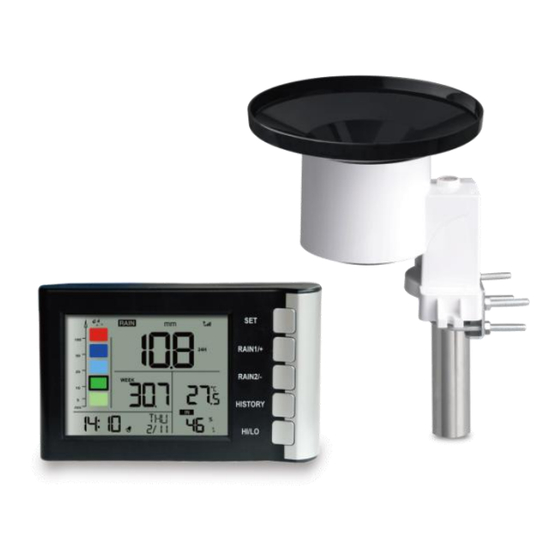
High Precision Digital Rain Gauge
with Indoor Temperature and Humidity
Model: WH5360
Thanks for your purchasing of the WH5360 High
Precision Digital Rain Gauge with indoor temperature
and humidity. To ensure the best product performance,
please read this manual and retain it for future reference.
Note: The stainless steel pole for the rain gauge is not
included.
Advertisement
Table of Contents

Related Manuals for ECOWITT WH5360


Summary of Contents for ECOWITT WH5360
- Page 1 High Precision Digital Rain Gauge with Indoor Temperature and Humidity Model: WH5360 Thanks for your purchasing of the WH5360 High Precision Digital Rain Gauge with indoor temperature and humidity. To ensure the best product performance, please read this manual and retain it for future reference.
-
Page 2: Table Of Contents
1 Table of Contents 1 Table of Contents............1 2 Unpacking..............2 3 Set up Guide..............3 3.1 Site Survey............4 3.2 Rain Gauge Sensor Set Up and Installation..5 3.2.1 Install rain gauge filter ......6 3.2.2 Install rain collector top ......7 3.2.3 Install Batteries in rain gauge sensor .. -
Page 3: Unpacking
2 Unpacking Open your rain gauge box and inspect that the contents are intact (nothing broken) and complete (nothing missing). Inside you should find the following: QTY Item Description Display Console Rain gauge sensor U-Bolts set for mounting on a pole (2pcs) Threaded nuts for U-Bolts set (M6 size) (4pcs) Metal mounting plate set to be used with U-Bolts Stainless steel filter (for rain collector) -
Page 4: Set Up Guide
Our product is continuously changing and improving, particularly online services and associated applications. To download the latest manual and additional help, please contact us at support@ecowitt.com or support.eu@ecowitt.net (EU/UK). 3 Set up Guide Note: We suggest you assemble all components of the rain gauge, including console in one location so you can easily test functionality. -
Page 5: Site Survey
3.1 Site Survey Location of the outdoor sensor is paramount to good data collection. Abbreviated instructions follow, but for a detailed reference, see: https://www.weather.gov/media/epz/mesonet/CWOP- Siting.pdf. Perform a site survey before installing the rain sensor. Consider the following: Ideally mounted at a height of 4 to 6 feet, or 1.5 to ... -
Page 6: Rain Gauge Sensor Set Up And Installation
3.2 Rain Gauge Sensor Set Up and Installation See Figure 1 to locate and understand all the parts of the rain gauge sensor once fully assembled. Figure 1: Sensor assembly components Rain collector top Battery compartment door LED Indicator Surface installation screw hole Bubble level U-bolt installation hole Table 2: Sensor assembly detailed items... -
Page 7: Install Rain Gauge Filter
3.2.1 Install rain gauge filter There’s a stainless steel filter included in the package. It’s aimed to stop leaves or bird's dropping to avoid the obstruction of the cone hole. The installation is as simple as the below figures show: Hook the filter hook on the edge of the rain collector to install the filter(as the figure 2 shows on the left). -
Page 8: Install Rain Collector Top
3.2.2 Install rain collector top Align the rain collector top with the rain bucket, pay attention to the lock groove position as shown on the left side in Figure 3. Next, lock the top clockwise to the lock groove position, as shown on the right side of the figure, until it comes to a stop and the top cannot be removed from the bucket. - Page 9 Figure 4: Rain gauge sensor battery installation diagram The LED indicator on the top of the battery door (item 2) will turn on for 4 seconds and then flash once every 49 seconds indicating sensor data transmission. If you did not pay attention, you may have missed the initial indication.
-
Page 10: Mounting
3.2.4 Mounting 3.2.4.1 Before you mount Before proceeding with the outdoor mounting detailed in this section, you may want to skip to setup instructions in section 3.4 and onwards first, while you keep the assembled rain gauge sensor nearby (although preferably not closer than 5 ft. from the display console). - Page 11 Figure 5: Rain gauge installation with U-bolts Note: Use the bubble level one the side of the rain gauge as a guide to verify that the sensor is leveled (for proper measurements).
-
Page 12: Best Practices For Wireless Communication
3.2.4.3 Mounting with screws The mounting assembly also includes two screws for installation on a flat surface. Figure 6: Rain gauge sensor mounting with screws installation diagram Note: Use the bubble level beside the rain sensor as a guide to verify that the sensor is leveled. Use shims as necessary to achieve level installation. - Page 13 free wireless communication between both sensor and the console: Indoor/outdoor sensor placement: The sensor will have the longest reach for its signal when mounted or hung vertically. Avoid laying it down on a flat surface. Electro-Magnetic Interference (EMI). Keep the ...
- Page 14 Metal Barriers. Radio frequency will not pass through metal barriers such as aluminum siding or metal wall framing. If you have such metal barriers and experience communication problems, you must change the placement of sensor package and or console. The following table shows different transmission media and expected signal strength reductions.
-
Page 15: Console Display
3.4 Console Display See Figure 7 to help you identify elements of the console’s display screen. - Page 16 Figure 7: Display Console Screen Layout Rainfall data display Alarm icon Rainfall grade graph Date/Week Rainfall of 10. Signal icon day/week/month/year display Time 11. Wall-mounted hole Rain rate/event/1h/24h display 12.Table stand Indoor temperature 13. Battery door Indoor humidity Table 4: Display console detailed items...
-
Page 17: Initial Display Console Set Up
3.4.1 Initial Display Console Set Up Immediately after power up (installing batteries), the unit will turn on the display, and the unit will start to look for reception of the outdoor sensor data. This may take up to 3 minutes. Figure 8: Console Normal Display... -
Page 18: Key Functions
3.4.2 Key functions Figure 9: Buttons next to the display There is a set of five keys on the right side of the display console. The following tables briefly explains the function of these keys. - Page 19 Button Description enter the setting mode display RATE, EVENT, 1H, 24H RAIN 1/+ (normal mode) or + ( programming mode) display DAY, WEEK, MONTH, RAIN 2/- YEAR, TOTAL( normal mode) or– ( programming mode) display history records / return to HISTORY normal mode display the MAX, MIN value ( normal...
-
Page 20: Normal Mode
3.4.3 Normal Mode While in normal display, press the RAIN 1/+ button to alternate the display of: Display rain rate Display rain event Display rainfall total of 1h Display rainfall total of 24h Note: Hold the button RAIN 1/+ over 5s will clear the current rainfall data displayed. -
Page 21: Setting Mode
3.4.4 Setting Mode While in normal display, hold the button SET for 2 seconds to enter Setting Mode. The first setting will begin flashing. You can press the SET button again to skip any step, as defined below. Beep on/off ... -
Page 22: Calibration Mode
3.4.5 Calibration Mode While in Calibration mode, press RAIN1/+ or RAIN2/- buttons change calibration coefficient (range: 0.1-5.0; default: 1.00). Hold the button for 2 seconds can change rapidly. Before you calibrate the coefficient, please read the following first: Rain Gauge Accuracy Cross Check To tell if the rain gauge is accurate or not, it is not correct to compare to a rain meter nearby around. -
Page 23: Rain History Mode
calibrated manual gauge, to see if they are matching or not. Since there may be some water left in the tip bucket, and also some on the rain collector itself, the observed rain is normally slightly less than the actual rainfall, but his is normally within 5%. If the deviation is larger than this, then you can change rain calibration settings accordingly, or contact the customer service for replacement. -
Page 24: Min/Max Mode
3.4.7 MIN/MAX Mode While in normal display, press the button HI/LO to alternate the following max/min records with timestamp: Indoor temperature Max Indoor temperature Min Indoor humidity Max Indoor humidity Min Note: Hold the button RAIN2/- over 5s will clear the current max/min records with timestamp displayed. - Page 25 Rainfall Rate HI alert ON/OFF; Rainfall Rate HI alert value setting; Rainfall Event HI alert ON/OFF; Rainfall Event HI alert value setting; Indoor temperature HI alert ON/OFF; Indoor temperature HI alert value setting; Indoor temperature LO alert ON/OFF; ...
-
Page 26: Factory Reset/Clear Memory
The setting mode will return to normal display while idle for 15s or by pressing the button HISTORY. 3.4.9 Factory Reset/Clear Memory While in normal display, hold the button SET and HI/LO at the same time and power up the display will reset the device to Factory Mode. - Page 27 Indoor temperature and humidity MAX,MIN records with timestamp Temperature/humidity high/low alert c) Rain Every 49 second the unit will receive wireless rain sensor. Rain1 record view: RATE,EVENT,1H,24H. Rain2 record view: DAY, WEEK, MONTH, YEAR, TOTAL Rain1 ( Rate, Event, 1h, 24h rain data ) against ...
- Page 28 During the synchronization, it will reduce one signal segment if it has not received the signal once from the transmitter. It will increase one signal segment if it has received the signal once. Lost the signal once Received the signal once...
-
Page 29: Maintenance
5. Maintenance The following steps should be taken for proper maintenance of your station Clean Rain Gauge Check the rain gauge every 3 months. Rotate the funnel counterclockwise and lift it up. Clean the funnel and bucket with a damp cloth to remove any dirt, debris and insects. - Page 30 Figure 10: Rain gauge maintenance Replacing batteries regularly Batteries of the outdoor sensor array should be replaced every 1-2 years. In applications where data dropouts cannot be tolerated, check the batteries every 3 months and apply a corrosion preventing compound (not included) on the battery terminals for protection.
-
Page 31: Troubleshooting Guide
6. Troubleshooting Guide Problem Solution Wireless remote Check the remote-transmitter LED for (outdoor unit) flashing. not reporting in The outside sensor has an LED under the to console. plastic, just above battery compartment. The LED will flash every 49 seconds. There are dashes (--) on the If the LED is not flashing every 49... - Page 32 Problem Solution 1. Make sure you have fresh batteries in the display console. 2. With the sensor array and console 10 feet away from each other, remove the batteries from the display console and wait 10 seconds. Put the batteries back 3.
- Page 33 Problem Solution together. 3. If the sensor assembly is too close (less than 13cm (5in), move the sensor assembly away from the display console. 4. Make sure the remote sensors are not transmitting through solid metal like aluminum siding (acts as an RF shield), or earth barrier (down a hill).
-
Page 34: Specifications
7. Specifications Outdoor data Measuring interval: 49 sec Transmission distance in open field: 100m(300 feet) Frequency: 915/868/433MHz depending on location (North American:915MHz; Europe:868MHz; Other areas:433MHz) Indoor data Measuring interval: about 60s Rain fall measuring range: 0--6000mm; Accuracy: ±5% Indoor temperature range: -10˚C-60˚C (14℉ to + 140℉) Accuracy: ±... -
Page 35: Warranty Information
Battery life: Minimum 12 months for base station Minimum 12 months for outdoor sensor 8. Warranty Information We disclaim any responsibility for any technical error or printing error, or their consequences. All trademarks and patents are recognized. We provide a 1-year limited warranty on this product against manufacturing defects...
Need help?
Do you have a question about the WH5360 and is the answer not in the manual?
Questions and answers