
Related Manuals for ECOWITT LDS01


Summary of Contents for ECOWITT LDS01
- Page 1 Laser Distance Meter for water level/ snow depth Measurement User Manual Model No. LDS01 https://s.ecowitt.com/NJ5PG6...
-
Page 2: Table Of Contents
2.1 Measurement Principle ........... 10 2.2 Measurement Intervals ........... 13 2.3 Heating function ............. 13 3. Ecowitt System ..............14 4. Ecowitt Network Provisioning ......... 16 5. Initial Setup via app or Web-UI ........17 5.1 Through App ............18 5.2 Through Web-UI .............27 6. - Page 3 7. Features ................37 8. Specifications ..............39 9. FAQs ................. 41 10. Warranty & Caution ............42 10.1 Warranty ..............42 10.2 IC Caution .............43 10.3 FCC Statement ............44 10.4 Care + Maintenance ..........45 10.5 Safety Disclaimer ..........46 11. After-sales Service ............47 12.
-
Page 4: Getting Started
1. Getting Started 1.1 Package List 1 x Laser Distance Meter (LDS01) (Main display unit, laser distance measurement module, and a battery compartment) 1 x Mounting bracket 1 x Drill guide card 1 x User manual ... -
Page 5: Overall Appearance
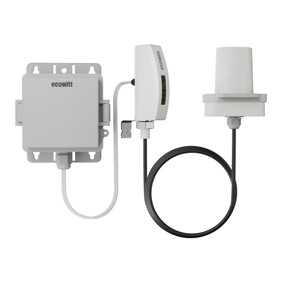
1.2 Overall Appearance Figure 1 Description Laser distance measurement module Mounting bracket Main display unit Battery compartment Connecting cable, length1.5m (between main display unit and battery compartment) Connecting cable, length1.5m (between main display unit and laser distance measurement module) Table 1... -
Page 6: Multiple Views And Sizes
1.3 Multiple views and sizes The LDS01 product is a complete unit, with the battery compartment connected to the main display unit by a cable, length 1.5m. The main display unit and the laser distance measurement module are also connected by a cable, length 1.5m. -
Page 7: Unit Setting And Find The Sensor Id
1.4 Unit setting and find the sensor ID The default unit is in meters. If you need to change the unit, please do so at this step. If no unit modification is needed, please proceed to the next step Section 1.5 Power up. 1.4.1 Remove the cover Unscrew the screws on the LCD unit and remove the cover. - Page 8 "1" represents the unit in meters (m). "ON" represents the unit in feet (ft). Figure 4 The unit switch 1.4.3 Find the sensor ID on LDS01 The Sensor ID is labeled inside the battery compartment, as illustrated below. Please note the ID number for future reference when comparing it to the Sensor ID displayed on the APP or console display.
- Page 9 Figure 5 1.4.4 Close the cover Close the cover and securely tighten the screws to prevent water leakage. Ensure that the screw gaskets are not lost. If the gaskets are missing, the battery cover may not tighten properly, leading to waterproofing issues. Figure 6 Close the cover...
-
Page 10: Power Up
1.5 Power up Power-Up Caution: 1. Do not place the device with the probe facing downward for an extended period to avoid prolonged heating. 2. Ensure the device does not operate in an over-range state to prevent prolonged heating. 3. Remove the batteries if the device will not be used for an extended period to avoid accidental heating or battery damage. - Page 11 Figure 7...
- Page 12 1.5.2 Display check After installing the batteries, the screen will display the frequency(like 915/868/433) for 3 seconds, followed by the initial setup for 2 seconds, and then show the current measured distance from the level. Start-up Screen Description The full-screen display for 1 seconds The RF frequency information display for 3...
-
Page 13: Measurement
2. Measurement 2.1 Measurement Principle The LDS01 uses laser pulse technology, emitting a laser beam and calculating the distance between the target surface and the sensor by measuring the time it takes for the laser to reflect back. Figure 8... - Page 14 Figure 9 This is a non-contact measurement method suitable for complex environments. When the laser encounters an uneven water surface, the device will automatically calculate an average value as the distance.
- Page 15 Figure 10 Measuring tank Note: When the water depth level is less than 20cm, the laser may penetrate the liquid surface and measure the bottom distance instead, leading to inaccurate results. It is recommended that the water level be kept above 20cm.
-
Page 16: Measurement Intervals
2.2 Measurement Intervals Regular measurement: measures every 20 seconds, with RF data transmission every 79.75 seconds. Fast Measurement Mode: If the measurement changes by more than 5% compared to the previous RF transmission, the device switches to Fast Measurement Mode. In Fast Measurement Mode, measurements are taken every 10 seconds and transmits RF data immediately. -
Page 17: Ecowitt System
4 meters, ensuring more accurate and reliable data. The LDS01 is equipped with a heating function that automatically activates when dew, fog, ice, or other conditions are detected. This feature eliminates fog to ensure accurate measurements during snow monitoring or long-term water tracking. - Page 18 To send data to the ecowitt cloud server and enable users to access it via ecowitt mobile app, LDS01 product requires the setup of a console/gateway. We at Ecowitt are very conscientious about your possible concerns regarding sending your data into a cloud. Not only...
-
Page 19: Ecowitt Network Provisioning
4. Ecowitt Network Provisioning The following models will be updated to support LDS01. However, due to the large number of models, we are unable to provide a specific date. Please stay updated with our version releases. Prepare a console/gateway and upgrade to the latest firmware version. -
Page 20: Initial Setup Via App Or Web-Ui
5. Initial Setup via app or Web-UI This section explains how to configure the LDS01, including total height setup, calibration function and low/high-level alert notifications. Glossary of Terms in the section Total Height Total Height: The distance from the bottom of the device to the bottom of the measured object. -
Page 21: Through App
5.1 Through App Ensure that your phone and the console are connected to the same Wi-Fi network to proceed. 5.1.1 Default mode: "Air" value mode The device defaults to "Air" value mode. If the total height is set to 0 or left unset, depth measurement will be disabled, and only the air distance will be displayed. - Page 22 5.1.2 "Depth" value mode and Total Height setup: After the Total Height setup is completed, the system will automatically switch to "Depth" value mode. 1. Tap the top-right menu ("...") and select Calibration. 2. Enter the total height as a preset value. 3.
-
Page 23: Calibration Setup
5.1.3 Calibration Setup: If the measurement result appears to be inaccurate, you can input an offset value to correct it. 1. Tap the top-right menu ("...") and select Calibration. 2. Enter the offset value. Figure 14... - Page 24 5.1.4 Low/high-Level Alerts Setup: You can set alerts for the minimum or maximum water level. 1. Tap the top-right menu ("...") and select "Alerts". 2. Enter the desired minimum or maximum value, then tap "Confirm". 3. The alerts detail is displayed as shown. Figure 15...
-
Page 25: Sensor Management
1. Make sure your phone's Wi-Fi is connected to the same network as the console/gateway. 2. Run the "ecowitt" APP, tap on the three dots from the upper right corner of the dashboard, then select "Sensor ID". 3. The current LDS01 Sensor ID is displayed on this page. - Page 26 Figure 17 4. Make sure the sensor ID matches. Configuration & Multi-Channel Setup: Generally, the data from the LDS01 is automatically received by the console/gateway. If the data is not received successfully or multiple LDS01 sensors need to be configured, you can configure it using the following steps.
- Page 27 2. Run the "ecowitt" APP Tap on the three dots from the upper right corner of the dashboard, then select "Sensor ID". If it is grayed out, you may close the APP, and try it again. With the "Sensor ID"...
- Page 28 3. Multi-Channel Setup For example, if you want the data from a specific LDS01 to be assigned to "CH X" ("X" from 1 to 4). Select the "CH X" channel, click Edit button; Input the sensor ID, and enable it;...
- Page 29 5.1.6 Heater-on Counter Figure 20 The total number of times the heating function has been activated. Heater-on Counter will only reset to zero after the console/gateway is restored to factory settings. If there is a rapid increase in the counter, such as more than 30 counts per day, you should check the sensor setup and...
-
Page 30: Through Web-Ui
make adjustments to optimize for better results. 5.2 Through Web-UI Connect to the console’s web page/WebUI (http://IP-address-of console in your local network) using a mobile phone or PC. Total Height Setup: Enter the tank total height as a preset value, and the system automatically calculates and displays the corresponding water level. - Page 31 Figure 21...
-
Page 32: Mounting
Calibration Setup: If the measurement result appears to be inaccurate, you can input an offset value to correct it. 6. Mounting 6.1 Drill holes with the drill guide card Ensure that the installation surface is level. Figure 22 Please mark the drilling position with a pen. Do not drill directly on the card to avoid it getting caught in the drill bit!... - Page 33 6.1.1 Central Hole Use the drill guide card to position and drill the central hole with a diameter of 45–50 mm, then cover it on the installation surface. 6.1.2 Screw Holes Drill holes according to the material type: For metal or plastic surfaces, drill holes with a diameter of 2.3–2.5 mm.
-
Page 34: Mount The Bracket
6.2 Mount the bracket 6.2.1 Secure the bracket with screws. Figure 23... - Page 35 Figure 24 Bracket size (unit:mm) Note: When installing on top of the water tank, pay attention to the distance from the tank wall. For a 100 cm total height, the distance from the tank wall should be ≥ 3.5 cm. ...
- Page 36 Figure 25 6.2.2 Fix the Laser distance measurement module Attach the Laser distance measurement module to the bracket. You should hear a "latch engaging click sound" when it’s securely fixed. Note: Use the bubble level to ensure the installation is level.
- Page 37 Figure 26 Bubble level Figure 27 Fix the Laser distance measurement module...
- Page 38 6.2.3 Fix the main display unit Figure 28 You can use the provided screws (PA 3*15mm) to fix the main display unit.
- Page 39 6.2.4 Fix the battery compartment Figure 29 You can use the provided screws(PWA 3.0*20mm) or zip ties to secure the battery compartment.
-
Page 40: Features
Equipped with an easy-to-read LCD screen that refreshes data every minute, keeping you updated on current measurements. Supports data upload to the Ecowitt cloud service via a console/gateway. View real-time data and generate statistical charts through ecowitt app, enabling historical data analysis and trend monitoring. - Page 41 bracket and a bubble level on top, allowing easy and accurate horizontal installation for long-term stability and measurement precision. Heating Function: The unit has equipped an auto heater that balances between battery life and performance. When unfavorable conditions, like dew, fog, ice gathered on the lens, the device will turn on the heater and ensure a reliable result.
-
Page 42: Specifications
8. Specifications Model LDS01 Name Laser Distance Meter Dimension of laser distance 87*64*74 (mm) L*W*H measurement module Dimension of main display unit 102*25*49 (mm) L*W*H Dimension of battery 113*103*61 (mm) L*W*H compartment Weight 370.5g Material of display unit HTN-LCD Main display unit: PC+ABS;... - Page 43 Measurement resolution 0.01m Normal Mode:20s; Measurement interval Fast Measurement Mode:10s Normal Mode:79.75s; RF transmission interval Fast Measurement Mode:10s Measurement zero point Bottom edge of the device 920/915/868/433MHz RF Connection Frequency (depending on local regulations) Over 100 meters (in open RF Wireless Range areas) Operating Temperature Range -20°C to 50°C(-4℉...
-
Page 44: Faqs
Q: What if the LDS01 cannot connect to the console? 1. Ensure that the console/gateway and device are of the same frequency;... -
Page 45: Warranty & Caution
10. Warranty & Caution 10.1 Warranty We disclaim any responsibility for any technical error or printing error, or the consequences thereof. All trademarks and patents are recognized. We provide a 2-year limited warranty on this product against manufacturing defects, or defects in materials and workmanship. -
Page 46: Ic Caution
10.2 IC Caution English: This device contains licence-exempt transmitter(s)/receiver(s) that comply with Innovation, Science and Economic Development Canada's licence-exempt RSS(s). Operation is subject to the following two conditions: 1. This device may not cause interference. 2. This device must accept any interference, including interference that may cause undesired operation of the device. -
Page 47: Fcc Statement
10.3 FCC Statement FCC: This device complies with part 15 of the FCC Rules. Operation is subject to the condition that this device does not cause harmful interference (1) this device may not cause harmful interference, and (2) this device must accept any interference received, including interference that may cause undesired operation. -
Page 48: Care + Maintenance
the user is encouraged to try to correct the interference by one or more of the following measures: -- Reorient or relocate the receiving antenna. -- Increase the separation between the equipment and receiver. -- Connect the equipment into an outlet on a circuit different from that to which the receiver is connected. -
Page 49: Safety Disclaimer
10.5 Safety Disclaimer The laser power(heating power not included) of the LDS01 distance meter is ≤ 3mW, which is within safe limits and will not cause harm to skin or eyes. It is safe to use under normal operating conditions Manufacturer: Shenzhen Fine Offset Electronics Co., Ltd. -
Page 50: After-Sales Service
11. After-sales Service Order Issues: If you encounter any missing or incorrect shipments of Ecowitt products purchased, please reach out to the respective platform's customer service from the store you bought product for assistance. Usage Inquiries: For any issues related to product usage, feel free to contact our customer support team at support@ecowitt.com.
Need help?
Do you have a question about the LDS01 and is the answer not in the manual?
Questions and answers