Table of Contents
Advertisement
withPiezoelectric Rain Gauge, Light &
UV, Thermo-hygrometer Sensors
Contents
1. Warnings and Cautions ................................................ 3
1.1 Optional other accessories (sold separately) ......... 3
1.2 Features ..................................................................4
2. Overview ......................................................................5
3. Setup Guide ..................................................................6
3.1 Install batteries in sensor package ......................... 6
assembly .......................................................................8
3.2.1 Before you mount ........................................... 8
3.2.2 Mounting .........................................................9
3.2.3 Reset Button and Transmitter LED .............. 12
4. Specification .............................................................. 12
4.1 Transmission between gateway and sensor .........12
4.2 Measurement Specification ................................. 13
4.3 Power consumption ............................................. 14
5. Warranty Information ................................................ 14
Ultrasonic Anemometer
Model: WS90
1
Advertisement
Table of Contents

Related Manuals for ECOWITT WS90


Summary of Contents for ECOWITT WS90
-
Page 1: Table Of Contents
Ultrasonic Anemometer withPiezoelectric Rain Gauge, Light & UV, Thermo-hygrometer Sensors Model: WS90 Contents 1. Warnings and Cautions ..........3 1.1 Optional other accessories (sold separately) ..3 1.2 Features ..............4 2. Overview ..............5 3. Setup Guide ..............6 3.1 Install batteries in sensor package ......6 3.2 Mount ultrasonic anemometer with piezoelectric... - Page 2 Quick start, APP, manuals, Compatibility table, firm ware https://s.ecowitt.com/MP7YJJ Help Our product is continuously changing and improving, particularly online services and associated applications. To download the latest manual and additional help, please contact our technical support team: support@ecowitt.com support.eu@ecowitt.net (EU/UK)
-
Page 3: Warnings And Cautions
1. Warnings and Cautions Note: 1. The last firmware in QR code on the box 2. Advance setting on Embeded Web page 192.168.4.1 (You need a computer or phone linking WLAN gateway) 1.1 Optional other accessories (sold separately) Accessories: 12V/1A power extension cord; Bird spikes Note: Batteries for the sensor package are not included. -
Page 4: Features
Please contact us at support@ecowitt.com for theextension cord information if needed. 1.2 Features • Piezoelectric rain gauge; • Ultrasonic anemometer (start wind speed 0.3m/s); • Temperature; • Humidity; • Solar light intensity and UV index; • Waterproof IPX5; • Heater and additional power supply;... -
Page 5: Overview
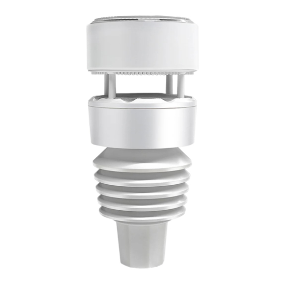
2. Overview Figure 1: Sensor package assembly components... -
Page 6: Setup Guide
Description Description Piezoelectric rain sensor Battery compartment array Light& UV sensor, LED Temperature & humidity indicator sensor USB port (factory use fixed bolt only ) Solar Panel Heating power cable connector Ultrasonic wind speed Calibration button sensor (factory use only ) NORTH alignment Reset button indicator... - Page 7 If sensor has been put outside for some time, and solar panel has charged up the internal accumulator fully or partially, if you install the 2 AA backup battery, the system might not start up properly. So you can always make a system reset by press the “Reset”...
-
Page 8: Mount Ultrasonic Anemometer With Piezoelectric Assembly
up the accumulator and supply system power afterwards. when in high altitude area,during wintertime, sunshine time is short, thus system needs to be powered from this backup battery, we recommend Lithium batteries to be used for cold weather climates. Please avoid alkaline batteries, especially when internal heater is to be activated during cold and wet weather conditions as when heater... -
Page 9: Mounting
3.2.2 Mounting You can attach a pole (not included) to a permanent structure and then attach the sensor package to it (see Figure 3). The install hole will accommodate a pole diameter of 1.0 inch (pole not included). Figure 3: Sensor package mounting diagram 6-1... - Page 10 Make sure the mounting pole is vertical, or very close to it. Use a level as needed. If optional extension cord is added, connect the cord to the connector and insert the USB port into the AC adaptor as Figure 4 show: Figure 4: Sensor package mounting diagram 6-2...
- Page 11 Now you will need to align the whole package in the proper direction by rotating it on top of the mounting pipe as needed. Locate the arrow labeled “NORTH” that you will find on top of the connector tubeof the sensor package (item 6).
-
Page 12: Reset Button And Transmitter Led
3.2.3 Reset Button and Transmitter LED In the event the sensor package is not transmitting, reset the sensor. Using a bent-open paperclip, press and hold the RESET BUTTON (item 12) to affect a reset: the LED turns on while the RESET button is depressed, and you can now let go. -
Page 13: Measurement Specification
• The wind gust reading will be the max wind speed in the past 28s. • When the wind speed is lower than 5m/s,the dispersion of wind direction will increase. 4.2 Measurement Specification Measurement Range Accuracy Resolution Wind speed 0m/s to 0.1m/s <10m/s, ±... -
Page 14: Power Consumption
4.3 Power consumption Power Specification Anemometer sensor Solar panel (built-in): 6.5V/4mA Anemometer sensor 2 x AA 1.5V battery (not (backup) included) Note: The primary power source for the sensor is the solar panel. When available solar power (light over recent period) is insufficient, the batteries will be used. 5. - Page 15 installation or removal from a fixed installation, normal set-up adjustments, claims based misrepresentation by the seller,or performance variations resulting from installation-related circumstances.