Table of Contents
Advertisement
Quick Links
OM‐05669‐OB01
July 23, 2004
Rev. F 11‐21‐17
INSTALLATION, OPERATION,
AND MAINTENANCE MANUAL
WITH PARTS LIST
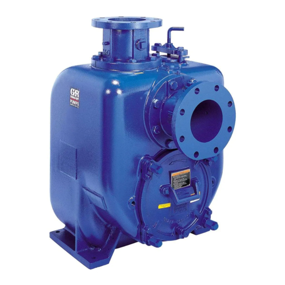
SUPER U SERIES PUMPS
MODEL
U6B60S-B
INCLUDING: /F, /FM, /WW
THE GORMAN‐RUPP COMPANY D MANSFIELD, OHIO
www.grpumps.com
D
GORMAN‐RUPP OF CANADA LIMITED
ST. THOMAS, ONTARIO, CANADA
Printed in U.S.A.
e
2004 The Gorman‐Rupp Company
Advertisement
Table of Contents

Subscribe to Our Youtube Channel
Related Manuals for GORMAN-RUPP U6B60S-B/F


Summary of Contents for GORMAN-RUPP U6B60S-B/F
- Page 1 OM‐05669‐OB01 July 23, 2004 Rev. F 11‐21‐17 INSTALLATION, OPERATION, AND MAINTENANCE MANUAL WITH PARTS LIST SUPER U SERIES PUMPS MODEL U6B60S-B INCLUDING: /F, /FM, /WW THE GORMAN‐RUPP COMPANY D MANSFIELD, OHIO www.grpumps.com GORMAN‐RUPP OF CANADA LIMITED ST. THOMAS, ONTARIO, CANADA Printed in U.S.A.
- Page 2 Register your new Gorman‐Rupp pump online at www.grpumps.com Valid serial number and e‐mail address required. RECORD YOUR PUMP MODEL AND SERIAL NUMBER Please record your pump model and serial number in the spaces provided below. Your Gorman‐Rupp distributor needs this information when you require parts or service. Pump Model: Serial Number:...
-
Page 3: Table Of Contents
TABLE OF CONTENTS INTRODUCTION ..........PAGE I - 1 SAFETY - SECTION A . - Page 4 TABLE OF CONTENTS (continued) TROUBLESHOOTING - SECTION D ......PAGE D - 1 PREVENTIVE MAINTENANCE .
-
Page 5: Introduction
SUPER U SERIES OM-05669 INTRODUCTION Thank You for purchasing a Gorman‐Rupp pump. For information or technical assistance on the Read this manual carefully to learn how to safely power source, contact the power source manufac install and operate your pump. Failure to do so turer's local dealer or representative. -
Page 6: Safety - Section A
SUPER U SERIES OM-05669 SAFETY - SECTION A This information applies to the Super U 5. Close the suction and discharge Series basic pumps. Gorman‐Rupp has valves. no control over or particular knowledge 6. Vent the pump slowly and cau of the power source which will be used. - Page 7 OM-05669 SUPER U SERIES Do not operate the pump against a Death or serious personal injury and closed discharge valve for long periods damage to the pump or components of time. If operated against a closed dis can occur if proper lifting procedures charge valve, pump components will are not observed.
-
Page 8: Installation - Section B
SUPER U SERIES OM-05669 INSTALLATION - SECTION B Review all SAFETY information in Section A. specific application. Since the pressure supplied to the pump is critical to performance and safety, Since pump installations are seldom identical, this be sure to limit the incoming pressure to 50% of section offers only general recommendations and the maximum permissible operating pressure as practices required to inspect, position, and ar... -
Page 9: Preinstallation Inspection
OM-05669 SUPER U SERIES PREINSTALLATION INSPECTION POSITIONING PUMP Lifting The pump assembly was inspected and tested be Pump unit weights will vary depending on the fore shipment from the factory. Before installation, mounting and drive provided. Check the shipping inspect the pump for damage which may have oc tag on the unit packaging for the actual weight, and curred during shipment. -
Page 10: Line Configuration
SUPER U SERIES OM-05669 compatible with the liquid being pumped. If hose is Fittings used in suction lines, it must be the rigid‐wall, rein Suction lines should be the same size as the pump forced type to prevent collapse under suction. Us inlet. -
Page 11: Suction Line Positioning
OM-05669 SUPER U SERIES If it is necessary to position inflow close to the suc Suction Line Positioning tion inlet, install a baffle between the inflow and the The depth of submergence of the suction line is suction inlet at a distance 1 1/2 times the diameter critical to efficient pump operation. -
Page 12: Bypass Lines
SUPER U SERIES OM-05669 In high discharge head applications (more than 30 feet), an excessive amount of liquid may be by passed and forced back to the wet well under the full working pressure of the pump; this will reduce If the application involves a high discharge overall pumping efficiency. -
Page 13: Automatic Air Release Valve
OM-05669 SUPER U SERIES plug to prevent injury to personnel from liters] per minute) will occur when the valve is fully closed. Be sure the bypass hot liquid. line is directed back to the wet well or tank to prevent hazardous spills. AUTOMATIC AIR RELEASE VALVE Consult the manual accompanying the Air Release Valve for additional information on valve installation... -
Page 14: Alignment
SUPER U SERIES OM-05669 Align spider insert type couplings by using calipers ALIGNMENT to measure the dimensions on the circumference of the outer ends of the coupling hub every 90_. The alignment of the pump and its power source is The coupling is in alignment when the hub ends critical for trouble‐free mechanical operation. - Page 15 OM-05669 SUPER U SERIES systems using two or more belts, make certain that the belts are a matched set; unmatched sets will cause accelerated belt wear. Do not operate the pump without the guard in place over the rotating parts exposed rotating parts can catch cloth...
-
Page 16: Operation - Section C
OM-05669 SUPER U SERIES OPERATION - SECTION C Review all SAFETY information in Section A. Add liquid to the pump casing when: 1. The pump is being put into service for the Follow the instructions on all tags, labels and de first time. -
Page 17: Operation
OM-05669 SUPER U SERIES If rotation is incorrect on a three‐phase motor, have pump components will deteriorate, and a qualified electrician interchange any two of the the liquid could come to a boil, build three phase wires to change direction. If rotation is pressure, and cause the pump casing to incorrect on a single‐phase motor, consult the liter... -
Page 18: Strainer Check
OM-05669 SUPER U SERIES the pressure relief valve assembly be replaced at On engine driven pumps, reduce the throttle each overhaul, or any time the pump casing over speed slowly and allow the engine to idle briefly be heats and activates the valve. Never replace this fore stopping. - Page 19 OM-05669 SUPER U SERIES Checking bearing temperatures by hand is inaccu rect level (see LUBRICATION in MAINTENANCE rate. Bearing temperatures can be measured ac AND REPAIR). Bearing overheating can also be curately by placing a contact‐type thermometer caused by shaft misalignment and/or excessive vi against the housing.
- Page 20 SUPER U SERIES OM-05669 TROUBLESHOOTING - SECTION D Review all SAFETY information in Section A. Before attempting to open or service the pump: 1. Familiarize yourself with this manual. 2. Lock out or disconnect the power source to ensure that the pump will remain inoperative.
- Page 21 OM-05669 SUPER U SERIES TROUBLE POSSIBLE CAUSE PROBABLE REMEDY PUMP STOPS OR Strainer clogged. Check strainer and clean if neces FAILS TO DELIVER sary. RATED FLOW OR PRESSURE Suction intake not submerged at Check installation and correct sub proper level or sump too small. mergence as needed.
- Page 22 SUPER U SERIES OM-05669 TROUBLE POSSIBLE CAUSE PROBABLE REMEDY BEARINGS RUN Bearing temperature is high, but Check bearing temperature regu TOO HOT within limits. larly to monitor any increase. Low or incorrect lubricant. Check for proper type and level of lubricant.
- Page 23 OM-05669 SUPER U SERIES Preventive Maintenance Schedule Service Interval* Item Daily Weekly Monthly Semi‐ Annually Annually General Condition (Temperature, Unusual Noises or Vibrations, Cracks, Leaks, Loose Hardware, Etc.) Pump Performance (Gauges, Speed, Flow) Bearing Lubrication Seal Lubrication (And Packing Adjustment, If So Equipped) V‐Belts (If So Equipped) Air Release Valve Plunger Rod (If So Equipped)
- Page 24 OM-05669 SUPER U SERIES PUMP MAINTENANCE AND REPAIR - SECTION E MAINTENANCE AND REPAIR OF THE WEARING PARTS OF THE PUMP WILL MAINTAIN PEAK OPERATING PERFORMANCE. STANDARD PERFORMANCE FOR PUMP MODEL U6B60S‐B, Including /F, /FM And /WW Based on 70_F (21_C) clear water at sea level Contact the Gorman‐Rupp Company to verify per...
- Page 25 OM-05669 SUPER U SERIES ILLUSTRATION PARTS PAGE Figure 1. Pump Model U6B60S-B, Including /F, /FM And /WW PAGE E - 2 MAINTENANCE & REPAIR...
- Page 26 OM-05669 SUPER U SERIES PARTS LIST Pump Model U6B60S-B, Including /F, /FM And /WW (From S/N 1289612 Up) If your pump serial number is followed by an “N”, your pump is NOT a standard production model. Contact the Gorman‐Rupp Company to verify part numbers. ITEM PART NAME PART...
- Page 27 OM-05669 SUPER U SERIES ILLUSTRATION SEAL AREA DETAIL Figure 2. Repair Rotating Assemblies PAGE E - 4 MAINTENANCE & REPAIR...
- Page 28 OM-05669 SUPER U SERIES PARTS LIST Repair Rotating Assemblies ITEM PART PART NAME NUMBER BEARING HOUSING 38251-418 10000 IMPELLER SHAFT 38514-825 16040 DBL ROW BALL BEARING 23422-412 DBL ROW BALL BEARING 23421-461 RETAINING RING S215 BEARING CAP 38322-415 10010 O‐RING S333 OIL SEAL S1917...
- Page 29 OM-05669 SUPER U SERIES PUMP AND SEAL DISASSEMBLY pump integrity are compromised by such practices. AND REASSEMBLY Review all SAFETY information in Section A. Follow the instructions on all tags, label and decals Before attempting to open or service the attached to the pump.
- Page 30 SUPER U SERIES OM-05669 use them to press the back cover out of the pump Install the shaft key (25). Install a lathe dog on the casing. drive end of the shaft (2) with the “V” notch posi tioned over the shaft key. With the impeller rotation still blocked, see Figure 3 Inspect the wear plate and back cover O‐rings (26 and use a long piece of heavy bar stock to pry...
- Page 31 OM-05669 SUPER U SERIES they are heavy enough for safe use and will not set of handles, or a length of pipe (1-13/16 inch damage the pump. [46 mm] minimum I.D.), and slide the complete ro tating assembly through the back cover opening After the rotating assembly is loosened, screw a (see Figure 4).
- Page 32 SUPER U SERIES OM-05669 Remove the bearing housing drain plug (24) and drain the lubricant. Clean and reinstall the drain plug. Bearings must be kept free of all dirt and Disengage the hardware (9 and 10) and slide the foreign material. Failure to do so will great bearing cap (6) and oil seal (8) off the shaft.
- Page 33 OM-05669 SUPER U SERIES just flush with the counterbored surface toward oil and the container must be absolutely clean. If the inside of the housing. the oil has been previously used, it must be thor oughly filtered. Heat the bearings to a uniform temperature no higher than 250_F (120_C), and slide the bearings onto the shaft, one at a time, until they are fully To prevent damage during removal from...
- Page 34 SUPER U SERIES OM-05669 Slide the shaft and assembled bearings into the Seal Installation bearing housing until the retaining ring on the out (Figures 2 and 6) board bearing seats against the bearing housing. Most cleaning solvents are toxic and flammable.
- Page 35 OM-05669 SUPER U SERIES RETAINER SEAL PLATE SPRING IMPELLER O‐RINGS SLEEVE O‐RING BELLOWS SHAFT SLEEVE IMPELLER SHAFT ROTATING STATIONARY ELEMENT ELEMENT OIL SEAL IMPELLER SHIMS STATIONARY SEAT DRIVE BAND Figure 6. Cartridge Seal Assembly the mylar storage tabs, if so equipped, from be tween the seal faces.
- Page 36 SUPER U SERIES OM-05669 proper clearance as described in Impeller Instal O‐RING ENGAGED WITH SEAL PLATE lation and Adjustment. BORE If necessary to reuse an old seal in an emer gency, carefully separate the rotating and station ary seal faces from the bellows retainer and sta tionary seat.
- Page 37 OM-05669 SUPER U SERIES Slide the rotating portion of the seal (consisting of reaching through the priming port with a feeler the integral shaft sleeve, spring centering washer, gauge. spring, bellows and retainer, and rotating element) onto the shaft until the seal faces contact. Proceed with Rotating Assembly Installation be...
- Page 38 SUPER U SERIES OM-05669 Suction Check Valve Installation USE TWO USE TWO REMAINING OPPOSING ADJUSTING SCREWS AND BACK COVER NUTS LOCKING COLLARS TO (Figure 1) SET FACE CLEARANCE TO PRESS BACK COVER INTO PUMP CASING Inspect the check valve assembly (33), and re INDEX COLLARS 3 place it if badly worn.
- Page 39 OM-05669 SUPER U SERIES holes in the back cover plate. Secure the locking Final Pump Assembly collars to the back cover plate with the hardware (5 (Figure 1) and 32). Install the two remaining back cover nuts snugly against the adjusting screws. Install the shaft key (25, Figure 2) and reconnect the power source.
- Page 40 SUPER U SERIES OM-05669 Under normal conditions, drain the bearing hous portant in areas where variable hot and ing once each year and refill with clean oil. Change cold temperatures are common. the oil more frequently if the pump is operated con For cold weather operation, consult the factory or a tinuously or installed in an environment with rapid lubricant supplier for the recommended grade of...
- Page 41 For Warranty Information, Please Visit www.grpumps.com/warranty or call: U.S.: 419-755-1280 Canada: 519-631-2870 International: +1-419-755-1352 GORMAN‐RUPP PUMPS...
Need help?
Do you have a question about the U6B60S-B/F and is the answer not in the manual?
Questions and answers