GORMAN-RUPP PAH SERIES Installation, Operation, And Maintenance Manual With Parts List
Hide thumbs
Also See for PAH SERIES:

Subscribe to Our Youtube Channel
Related Manuals for GORMAN-RUPP PAH SERIES


Summary of Contents for GORMAN-RUPP PAH SERIES
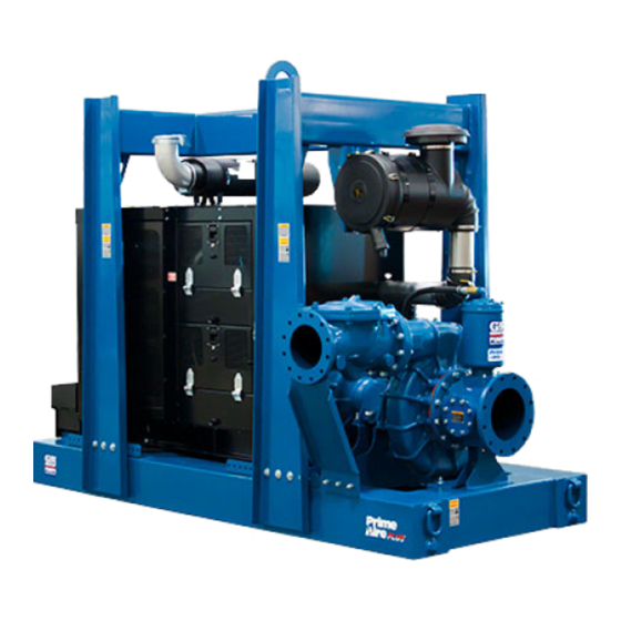
- Page 1 OM-07205-01 August 10, 2018 INSTALLATION, OPERATION, AND MAINTENANCE MANUAL WITH PARTS LIST PAH SERIESr PUMP MODEL PAH10B60-6135H FT4 GORMAN‐RUPP PUMPS www.grpumps.com 2018 Gorman‐Rupp Pumps Printed in U.S.A.
- Page 2 Register your new Gorman‐Rupp pump online at www.grpumps.com Valid serial number and e‐mail address required. The engine exhaust from this product contains chemicals known to the State of California to cause cancer, birth defects or other reproductive harm. RECORD YOUR PUMP MODEL AND SERIAL NUMBER Please record your pump model and serial number in the spaces provided below.
-
Page 3: Table Of Contents
TABLE OF CONTENTS INTRODUCTION ..........PAGE I - 1 SAFETY ‐... - Page 4 TABLE OF CONTENTS (continued) Engine Fuel Filter ............PAGE C - 4 Engine Oil .
-
Page 5: Introduction
PAH SERIES OM-07205 INTRODUCTION Thank You for purchasing a Gorman‐Rupp pump. HAZARD AND INSTRUCTION Read this manual carefully to learn how to safely DEFINITIONS install and operate your pump. Failure to do so could result in personal injury or damage to the The following are used to alert maintenance per... -
Page 6: Safety - Section A
PAH SERIES OM-07205 SAFETY ‐ SECTION A This information applies to Prime Aire the positive battery cable before per Series pumps. Refer to the manual ac forming any maintenance. Failure to do companying the engine or power so may result in serious personal injury. - Page 7 OM-07205 PAH SERIES After the pump has been installed, make Make sure the pump is level. Lower jack certain that the pump and all piping or stands and chock the wheels, if so hose connections are tight, properly equipped. Use caution when positioning supported and secure before operation.
-
Page 8: Installation - Section B
PAH SERIES OM-07205 INSTALLATION - SECTION B Review all SAFETY information in Section A. configuration, and priming must be tailored to the specific application. Since the pressure supplied Since pump installations are seldom identical, this to the pump is critical to performance and safety,... -
Page 9: Battery Installation
OM-07205 PAH SERIES c. Carefully read all tags, decals, and markings sion. Connect and tighten the positive cable first, on the pump assembly, and perform all duties then the negative cable. indicated. Note that the pump shaft rotates in the required direction. -
Page 10: Suction And Discharge Piping
PAH SERIES OM-07205 tially increase friction loss. If elbows are necessary, lubricated bearings, level mounting is es use the long‐radius type to minimize friction loss. sential to ensure sufficient lubrication to the pump bearings. Damage to the pump, including the bearings, shaft and/or bear... -
Page 11: Strainers
OM-07205 PAH SERIES Strainers the sump, and air entering the suction line will re duce pump efficiency. Be certain to use the strainer furnished with the pump; any spherical solids which pass through the If it is necessary to position inflow close to the suc... -
Page 12: Discharge Lines
PAH SERIES OM-07205 Figure 2. Recommended Minimum Suction Line Submergence vs. Velocity DISCHARGE LINES Siphoning If the application involves a high discharge head, gradually close the discharge Do not terminate the discharge line at a level lower than that of the liquid being pumped unless a si... -
Page 13: Float Switch Installation
OM-07205 PAH SERIES Float Switch Installation pipe is available, attach the float switch cable to the standpipe in the sump at the approxi mate desired liquid level. The Float Switch autostart system employs either a single or double float switch, where a bulb raises or lowers (floats) with the liquid level, thus activating b. - Page 14 PAH SERIES OM-07205 that the liquid in the priming chamber never fully Next, install a drain line between the pump drain freezes. and the wet well or sump. This line must remain submerged in the liquid below the pump down lev...
-
Page 15: Operation - Section C
OM-07205 PAH SERIES OPERATION - SECTION C OPERATION Review all SAFETY information in Section A. Make sure the pump is level. Lower jack Follow the instructions on all tags, labels and stands and chock the wheels, if so decals attached to the pump. -
Page 16: Operation In Extreme Heat
OM-07205 PAH SERIES and fittings tight to maintain maximum pump effi ciency. Pump Vacuum Check Never tamper with the governor to gain more power. The governor establishes Read the vacuum gauge with the pump primed safe operating limits that should not be and at operation speed. -
Page 17: Stopping
OM-07205 PAH SERIES vacuum suction gauge readings regularly to detect strainer blockage. Never introduce air or steam pressure into the Never disconnect any of the safety shut pump casing or piping to remove a blockage. This down features; this will void the warran... - Page 18 OM-07205 PAH SERIES Engine Fuel Filter and priming hopper to prevent damage from freez ing. Also, clean out any solids by flushing with a Consult the manual accompanying the engine, hose. Operate the pump for approximately one and change the fuel filter periodically as indicated.
- Page 19 OM-07205 PAH SERIES TROUBLESHOOTING - SECTION D Review all SAFETY information in Section A. 5. Close the suction and discharge valves. 6. Vent the pump slowly and cau tiously. 7. Drain the pump. Before attempting to open or service the pump: 1.
- Page 20 OM-07205 PAH SERIES TROUBLE POSSIBLE CAUSE PROBABLE REMEDY Check strainer and clean if neces Strainer clogged. PUMP STOPS OR FAILS TO DELIVER sary. RATED FLOW OR Check and clean check valve. Discharge check valve clogged. PRESSURE (cont.) Suction intake not submerged at Check installation and correct proper level or sump too small.
- Page 21 OM-07205 PAH SERIES TROUBLE POSSIBLE CAUSE PROBABLE REMEDY BEARINGS RUN Bearing temperature is high, but Check bearing temperature regu TOO HOT within limits. larly to monitor any increase. Low or incorrect lubricant. Check for proper type and level of lubricant.
- Page 22 OM-07205 PAH SERIES Preventive Maintenance Schedule Service Interval* Item Daily Weekly Monthly Semi‐ Annually Annually General Condition (Temperature, Unusual Noises or Vibrations, Cracks, Leaks, Loose Hardware, Etc.) Pump Performance (Gauges, Speed, Flow) Bearing Lubrication Seal Lubrication (And Packing Adjustment, If So Equipped) V‐Belts (If So Equipped)
- Page 23 OM-07205 PAH SERIES PUMP MAINTENANCE AND REPAIR - SECTION E MAINTENANCE AND REPAIR OF THE WEARING PARTS OF THE PUMP WILL MAINTAIN PEAK OPERATING PERFORMANCE. STANDARD PERFORMANCE FOR PUMP MODEL PAH10B60-6135H FT4 Based on 70 F (21 C) clear water at sea level Contact the Gorman‐Rupp Company to verify per...
- Page 24 OM-07205 PA SERIES PARTS PAGE ILLUSTRATION Figure 1. Pump Model PAH10B60-6135H FT4 PAGE E - 2 MAINTENANCE & REPAIR...
- Page 25 OM-07205 PAH SERIES Pump Model PAH10B60-6135H FT4 PARTS LIST (From S/N 1676116 Up) ITEM PART PART NAME NUMBER PUMP END ASSEMBLY 46183-009 POWER UNIT JD 6135H FT4 46143-218 PUMP MOUNTING KIT 48157-272 BATTERY SEE OPTIONS NOT SHOWN: G‐R DECAL GR-06...
- Page 26 OM-07205 PA SERIES ILLUSTRATION Figure 2. John Deere Power Unit PAGE E - 4 MAINTENANCE & REPAIR...
- Page 27 OM-07205 PAH SERIES PARTS LIST John Deere Power Unit ITEM PART NAME PART ITEM PART NAME PART NUMBER NUMBER BASE/FUEL TANK ASSY 41553-068 24150 STREET ELBOW RS08 11999 JD 6135H FT4 ENG 29224-495 CONNECTOR 26351-065 LIFT BAIL KIT 48274-825 HOSE ASSEMBLY...
- Page 28 OM-07205 PA SERIES ILLUSTRATION TO COMPRESSOR TO PRIMING CHAMBER VENTURI DETAIL ATTACH TO LIFT BAIL TO FUEL RETURN TO FUEL SUPPLY FUEL LEVEL SENDING UNIT DETAILS Figure 3. John Deere Power Unit (Cont'd) PAGE E - 6 MAINTENANCE & REPAIR...
- Page 29 OM-07205 PAH SERIES PARTS LIST John Deere Power Unit ITEM PART NAME PART ITEM PART NAME PART NUMBER NUMBER BASE/FUEL TANK ASSY 41553-068 24150 STREET ELBOW RS08 11999 JD 6135H FT4 ENG 29224-495 CONNECTOR 26351-065 LIFT BAIL KIT 48274-825 HOSE ASSEMBLY...
- Page 30 OM-07205 PA SERIES ILLUSTRATION Figure 4. Pump End Assembly PAGE E - 8 MAINTENANCE & REPAIR...
- Page 31 OM-07205 PAH SERIES Pump End Assembly PARTS LIST ITEM PART PART NAME NUMBER CHECK VALVE KIT 10" 48274-007 -CHECK VALVE 26642-127 -FLAPPER 26688-007 -O‐RING 25152-463 PIPE PLUG P04 15079 PIPE PLUG P08 15079 PUMP CASING SEE NOTE BELOW STUD C1412 15991 O‐RING...
- Page 32 OM-07205 PA SERIES ILLUSTRATION Ï Ï Ï Ï Ï Ï Ï Ï Ï Ï Ï Ï Ï Ï Ï Ï Ï Ï Ï Ï Ï Ï Ï Ï Ï Ï Ç Ï Ï Ï Ï Ï Ï Ï Ï Ï Ï Ï...
- Page 33 OM-07205 PAH SERIES PARTS LIST Repair Rotating Assembly ITEM PART PART NAME NUMBER IMPELLER 38621-784 11010 3.25" MECH SEAL 25285-823 SHAFT SLEEVE 31163-023 17000 O‐RING 25154-038 A HD SET SCREW GA0601-1/2 17090 WEAR RING 38691-638 11010 SEAL PLATE 38272-615 11010...
- Page 34 OM-07205 PA SERIES ILLUSTRATION Figure 6. Priming Chamber Kit PARTS LIST ITEM PART PART NAME NUMBER BALL VALVE 26631-054 STREET ELBOW RS16 11999 PRIMING CHAMBER ASSEMBLY 46112-709 HEX NUT D08 15991 LOCK WASHER J08 15991 STUD C0809 15991 BAFFLE 31113-011 17000 GASKET 38687-053 19060 INDICATES PARTS RECOMMENDED FOR STOCK...
- Page 35 OM-07205 PAH SERIES ILLUSTRATION Figure 7. Priming Chamber Assembly PARTS LIST ITEM PART PART NAME NUMBER PRIMING VALVE 26664-007 -ORIFICE BUTTON 26688-021 HEX HD CAPSCREW B0806 15991 LOCKWASHER J08 15991 PRIMING VALVE GASKET 38683-657 19060 PRIMING CHAMBER 38343-020 10000 STRAINER ASSY...
- Page 36 OM-07205 PA SERIES ILLUSTRATION Figure 8. Drive Assembly ITEM PART PART NAME NUMBER COUPLING KIT 48112-023 -COUPLING 24391-117 -BUSHING 24131-071 -LOCKWASHER 21171-905 -SOCKET HEAD CAPSCREW BD0814 15998 HEX HEAD CAPSCREW B0706 15991 LOCKWASHER J07 15991 -SOCKET HEAD CAPSCREW MBD1290 HEX HEAD CAPSCREW 22645-166 LOCKWASHER 21171-511...
- Page 37 OM-07205 PAH SERIES PUMP AND SEAL DISASSEMBLY any procedures not addressed in this manual are performed only after estab AND REASSEMBLY lishing that neither personal safety nor pump integrity are compromised by Review all SAFETY information in Section A. such practices.
- Page 38 Remove the hex nut and lock washer securing the orifice button to the linkage bar and unscrew the Use Only Genuine Gorman-Rupp re orifice button from the linkage bar. placement parts. Failure to do so may cre...
- Page 39 OM-07205 PAH SERIES Impeller and Wear Ring Removal and 15) and separate the seal plate from the ped estal (16). Position the seal plate on a flat surface (Figure 5) with the impeller side down. Use a wooden dowel or other suitable tool to press on the back side of Before attempting to remove the impeller (1) posi...
- Page 40 OM-07205 PAH SERIES sparks, and flame. Read and follow all precautions printed on solvent contain ers. Clean the bearings thoroughly in fresh cleaning Shaft and bearing disassembly in the field solvent. Dry the bearings with filtered compressed is not recommended. These operations air and coat with light oil.
- Page 41 OM-07205 PAH SERIES The bearings may be heated to ease installation. After installation, pack the bearings by hand with An induction heater, hot oil bath, electric oven, or lithium EP2 grease until fully lubricated. hot plate may be used to heat the bearing. The...
- Page 42 OM-07205 PAH SERIES lip positioned as shown in Figure 5. The face of the condition can cause premature bearing oil seal should be just flush with the outer face of failure. the bearing cap. The end of the shaft must extend 0.60 inch (15 mm) from the face of the bush...
- Page 43 OM-07205 PAH SERIES finished faces; even fingerprints on the faces can shorten seal life. If necessary, clean the faces with a non‐oil based solvent and a clean, lint‐free tissue. Wipe lightly in a concentric pattern to avoid Most cleaning solvents are toxic and scratching the faces.
- Page 44 OM-07205 PAH SERIES shaft threads are free of any tape residue and clean as required before proceeding with seal installa tion. Slide the rotating portion of the seal assembly onto This seal is not designed for operation at the shaft sleeve until the rotating element is just temperatures above 160_F (71_C).
- Page 45 OM-07205 PAH SERIES bracket and reinstall the pivot pin. Secure the pivot pump casing or binding and/or excessive pin with the previously removed “e‐clip”. wear will result. Adjust the orifice button seating as necessary by Lubricate the O‐ring (6) with light grease and install screwing the orifice button into or out of the linkage it in the groove in the O.D.
- Page 46 OM-07205 PAH SERIES g.) of lithium EP2 grease to the impeller end bear bearings into the pedestal, lubricate the bearings ing and 2 oz. (58 g.) of grease to the drive end bear as follows: ing. Do not over‐lubricate. Over‐lubrication can Impeller End Bearing: 6 oz.
- Page 47 For Warranty Information, Please Visit www.grpumps.com/warranty or call: U.S.: 419-755-1280 Canada: 519-631-2870 International: +1-419-755-1352 GORMAN‐RUPP PUMPS...
Need help?
Do you have a question about the PAH SERIES and is the answer not in the manual?
Questions and answers