Table of Contents
Advertisement
Quick Links
Advertisement
Table of Contents

Subscribe to Our Youtube Channel
Summary of Contents for Recon BLOCKAGE+
- Page 1 INSTALLATION MANUAL Document revision 1.0 Last revised: August 1, 2022...
- Page 2 Installation Manual © 2022 Intelligent Agricultural Solutions All Rights Reserved. Recon Blockage Plus™ Installation Manual. All content within is copyrighted by Intelligent Agricultural Solutions and may not be reprinted without permission. The content of this manual is furnished for informational use only, is subject to change without notice, and should not be construed as a commitment by Intelligent Agricultural Solutions.
-
Page 3: Table Of Contents
Securing Loose Harnessing ....................25 Installing the iPad Mount and App .................26 Installing the iPad Mount ....................26 Downloading the Recon Blockage Plus app ..............27 Connecting to the Gateway ....................28 Appendix A: Wiring Harness Diagrams .................29 Appendix B: System Configuration Table ................35 600840-000069, rev 1.0... - Page 4 Figure 20: Mounting the Wi-Fi antenna ..................21 Figure 21: Example Wi-Fi antenna mounting locations ..............22 Figure 22: Gateway connections ....................22 Figure 23: Installing the iPad mount ..................26 Figure 24: Recon Blockage Plus app ..................27 600840-000069, rev 1.0 Page 4 of 35...
-
Page 5: Related Documentation
Recon Blockage Plus™ Installation Manual Related Documentation Document Number Document Title 600820-000044 Recon Blockage Plus™ Quick Reference Guide 600820-000045 Recon Blockage Plus™ Troubleshooting Guide Recon Blockage Plus™ Operator’s Guide 600890-000075 600840-000069, rev 1.0 Page 5 of 35... -
Page 6: Introduction
Operators interact with the system via an iPad® app in the tractor cab. For instructions to use the system after installation, see the Recon Blockage Plus Operator’s Guide from the app’s Guides screen. -
Page 7: Installing Flow Sensors
Installing Flow Sensors Recon Blockage Plus™ Installation Manual Installing Flow Sensors Flow sensors detect when product is flowing through the run. Figure 1: Flow sensor Provided Parts Part Name Part Number Quantity 1-inch flow sensor or 153510-000022 or 1/run 1.25-inch flow sensor... -
Page 8: Figure 3: Installing Flow Sensors On A Manifold
Installing Flow Sensors Recon Blockage Plus™ Installation Manual Installing Flow Sensors Figure 3: Installing flow sensors on a manifold 1. If you are using adapters, snap them into the sensor in the orientation shown in Figure 3. 2. Cut each original run hose to about 8 inches (20.32 cm), or other length that allows for a downward flow and appropriate fit once the sensor and adapters (if applicable) are installed. -
Page 9: Installing Ecus
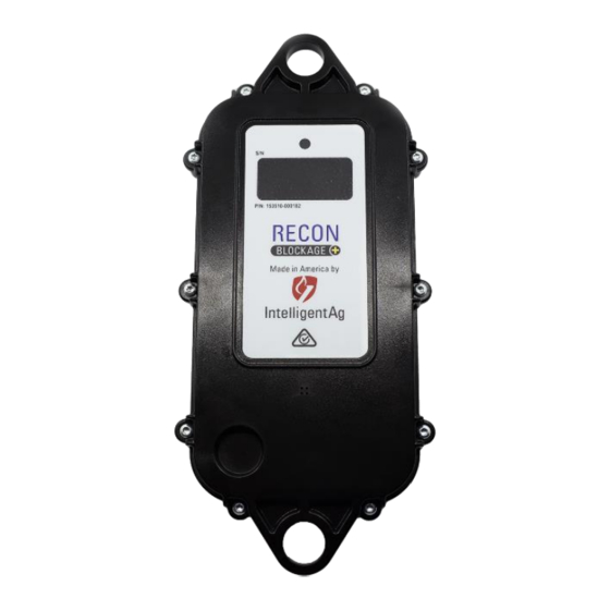
Installing ECUs Recon Blockage Plus™ Installation Manual Installing ECUs Electronic Control Units (ECUs) communicate the flow measurement data recorded by the flow sensors to the gateway. Figure 5: ECU Tools Needed • Standard socket set Installation Location Installed underneath each implement manifold. -
Page 10: Figure 7: Ecu Installed On A Tower (Standard Installation)
Installing ECUs Recon Blockage Plus™ Installation Manual Installing the ECUs (Standard Orientation) NOTE: This section is for installing the ECUs in the standard (vertical) orientation. If your dealer ordered you a horizontal mounting kit, skip this section and use the instructions in Installing the ECUs (horizontal installation). -
Page 11: Figure 9: Securing Ecu To Brackets
Installing ECUs Recon Blockage Plus™ Installation Manual 1. Determine the number of ECUs (153510-000182) you need per manifold. The number of ECUs you use depends on the number of runs per manifold. Runs per Manifold ECUs 7 or fewer 1 ECU for 2 manifolds... -
Page 12: Figure 10: Ecu Installed On A Tower (Horizontal Installation)
Installing ECUs Recon Blockage Plus™ Installation Manual Installing the ECUs (Horizontal Installation) NOTE: This section is for installing the ECUs in the horizontal orientation. If you’ve already installed your ECUs in the standard (vertical) installation, skip this section. Provided Parts... -
Page 13: Figure 12: Securing Ecu To Brackets
Installing ECUs Recon Blockage Plus™ Installation Manual 1. Determine the number of ECUs (153510-000182) you need per manifold. The number of ECUs you use depends on the number of runs per manifold. Runs per Manifold ECUs 7 or fewer 1 ECU for 2 manifolds... - Page 14 Installing ECUs Recon Blockage Plus™ Installation Manual 5. Orient the ECU so that the LED faces the tractor (recommended). Use a u-bolt (352013- 000007 or 356060-000108) to secure the center bracket to the manifold post. Hand tighten. 6. Adjust the assembly as needed and fully tighten the hardware.
-
Page 15: Connecting Auditory Tubes To Ecus
Connecting Auditory Tubes to ECUs Recon Blockage Plus™ Installation Manual Connecting Auditory Tubes to ECUs The auditory tubes on the sensors allow sound to be transmitted from the sensor to the ECU. Figure 13: Auditory tube Tools Needed • Pliers •... -
Page 16: Figure 14: Order To Connect Flow Sensors To Ecu
Connecting Auditory Tubes to ECUs Recon Blockage Plus™ Installation Manual 2. Locate the auditory tube of the sensor that is closest to the tractor when facing the back of the tractor (labeled “1” in Figure 14) and route it toward the ECU. connect the auditory tube to the port labeled “1”. -
Page 17: Installing The Work Switch
Installing the Work Switch Recon Blockage Plus™ Installation Manual Installing the Work Switch The work switch signals to the app when the implement is in or out of the ground. Figure 15: Work switch Provided Parts Part Name Part Number... -
Page 18: Installing The Work Switch
The work switch is tilted toward the wires when the implement is out of the ground. Take note of your work switch method. It will be configured during system configuration in the app. See the Recon Blockage Plus™ Operator’s Guide (Intelligent Ag document number 600890-000075) for instructions. Verifying Work Switch Installation Refer to Section 2.3 of the Operator’s Guide for instructions to verify that the work switch was... -
Page 19: Installing The Gateway
Installing the Gateway Recon Blockage Plus™ Installation Manual Installing the Gateway The gateway is a computing platform that sends ECU data to the iPad through the Wi-Fi antenna. Provided Parts Part Name Part Number Quantity Gateway 260 153010-000085 1/4” flat washer... -
Page 20: Figure 19: Example Gateway Mounting Locations
Installing the Gateway Recon Blockage Plus™ Installation Manual 1. Position the gateway (153010-000085) on the mounting bracket (353070-000079). The gateway can be mounted on the bracket in any direction, but the connectors should not face up when the bracket is mounted on the air cart or tractor. -
Page 21: Installing The Wi-Fi Antenna
Installing the Wi-Fi Antenna Recon Blockage Plus™ Installation Manual Installing the Wi-Fi Antenna The Wi-Fi antenna sends information from the Recon Blockage Plus™ system to the iPad. Provided Parts Part Name Part Number Quantity Needed SMA cap 251015-000139 SMA terminator jack... -
Page 22: Figure 21: Example Wi-Fi Antenna Mounting Locations
Installing the Wi-Fi Antenna Recon Blockage Plus™ Installation Manual 1. Thread the Wi-Fi antenna (252005-000010) cables through the hole in the mounting bracket (353070-000083) and through the nut. Tighten the nut to secure the antenna to the bracket. Do not over-torque. -
Page 23: Installing Harnessing
Recon Blockage Plus™ Installation Manual Installing Harnessing The wiring harnesses provide power from the tractor to Recon Blockage Plus™. NOTE: The gateway uses the tractor's key switch for proper operation. Make sure that the key switch is wired to the key switch terminal of the 3-pin power outlet in the tractor cab. -
Page 24: Installing The Gateway Harness (353050-000101)
Installing Harnessing Recon Blockage Plus™ Installation Manual 3. Chain the remaining 20’ ECU harnesses together by connecting S1 to S2. 4. Insert a 4 pin sealing plug (153510-000051) into S2 of the leftmost and the rightmost 20’ ECU harnesses at the end of the implement. -
Page 25: Securing Loose Harnessing
Installing Harnessing Recon Blockage Plus™ Installation Manual Securing Loose Harnessing Coil any loose harnessing around a hydraulic line or electrical wire. Secure all harnessing to the tractor and/or implement using cable ties (355032-000004) 600840-000069, rev 1.0 Page 25 of 35... -
Page 26: Installing The Ipad Mount And App
Installing the iPad Mount and App Recon Blockage Plus™ Installation Manual Installing the iPad Mount and App Installing the iPad Mount Part Name Part Number Quantity needed USB charger 254040-000002 Tablet mount arm 352004-000003 Rail attachment 352004-000004 iPad mount (for 9”-11.5” iPads) -
Page 27: Downloading The Recon Blockage Plus App
Use it to keep the iPad charged while using the system. Downloading the Recon Blockage Plus app To interface with the system, you need to download the Recon Blockage Plus app from the Apple App Store and install it onto your iPad. -
Page 28: Connecting To The Gateway
IASBlockage network “XXXXXX” represents the gateway’s serial number. 4. Open the Recon Blockage Plus app from the iPad’s Home screen. Follow the on-screen prompts to begin configuring your system For instructions to configure and use Recon Blockage Plus™ after installation, see the Recon Blockage Plus Operator’s Guide (600890-000015) from the app’s Manuals screen. -
Page 29: Appendix A: Wiring Harness Diagrams
Appendix A: Wiring Harness Diagrams Recon Blockage Plus™ Installation Manual Appendix A: Wiring Harness Diagrams 600840-000069, rev 1.0 Page 29 of 35... - Page 30 Appendix A: Wiring Harness Diagrams Recon Blockage Plus™ Installation Manual 600840-000069, rev 1.0 Page 30 of 35...
- Page 31 Appendix A: Wiring Harness Diagrams Recon Blockage Plus™ Installation Manual 600840-000069, rev 1.0 Page 31 of 35...
- Page 32 Appendix A: Wiring Harness Diagrams Recon Blockage Plus™ Installation Manual 600840-000069, rev 1.0 Page 32 of 35...
- Page 33 Appendix A: Wiring Harness Diagrams Recon Blockage Plus™ Installation Manual 600840-000069, rev 1.0 Page 33 of 35...
- Page 34 Appendix A: Wiring Harness Diagrams Recon Blockage Plus™ Installation Manual 600840-000069, rev 1.0 Page 34 of 35...
-
Page 35: Appendix B: System Configuration Table
Appendix B: System Configuration Table Recon Blockage Plus™ Installation Manual Appendix B: System Configuration Table Use the following table to record notes about your system configuration. To view your current configuration in the app, tap Settings > Blockage > Edit ECUs Configuration, and then tap a Primary or Section.
Need help?
Do you have a question about the BLOCKAGE+ and is the answer not in the manual?
Questions and answers