Table of Contents
Advertisement
Quick Links
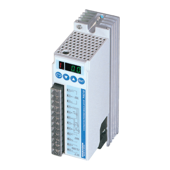
Thank you for purchasing a Shimaden PAC18 Series Single-Phase Thyristor Power Regulator.
After making sure the product fits the desired description, you should carefully read the instructions and get a good understanding of the contents before
attempting to operate the equipment.
Request
The instruction manual should be kept in a handy place where the end user can refer to it when necessary.
Preface
The instruction manual has been prepared for those involved in setup, wiring, operation or routine maintenance of PAC18 Series equipment.
The manual provides information concerning mounting, wiring and precautions when working with PAC18 Series equipment.
You should therefore keep it in a handy place to refer to when operating and handling the equipment.
Be sure to observe all precautions and adhere to the procedures provided in the manual.
Safety rules, precautions concerning equipment damage, additional instructions and notes are written based on the following headings.
◎Matters that could result in injury or death if instructions are not followed.
WARNING
◎Matters that could result in equipment damage if instructions are not followed.
CAUTION
◎additional instructions and notes
Note
PAC18 Series equipment is designed to control heater power, etc., of common industrial equipment. It should not be used for nuclear power generation,
traffic control, communications or medical equipment. You should either take appropriate safety measures or avoid using for control that could have a
serious effect on human life. The manufacturer shall not be liable for an accident that results if used without taking appropriate safety measures.
1. The power regulator should be used so the terminal elements in the control box, etc., are not touched by human beings.
2. The power regulator should not be used as a switch.
Even if output is zero, power is present in the capacitors and resistors of the output circuit, and could result in accident involving human life or serious
bodily injury due to electrical shock.
3. Radiation fins and chassis become extremely hot. Never touch the radiation fins or chassis. Doing so could result in burn injury.
4. Do not supply power when wiring. Doing so could result in electrical shock.
5. Do not touch terminal elements or other charged parts while conducting electricity. Also, do not introduce foreign objects or matter into the equipment.
If a foreign object or matter accidentally gets inside, be sure to turn off the power and make sure all is safe before introducing tools or your hands.
If there is danger of damage to any peripheral device or equipment due to failure of the power regulator, you should take appropriate safety measures such
as mounting a rapid fuse or overcurrent circuit breaker.
1. Concerning the
alert symbol on the power regulator's plate, a
The symbol is provided to prompt you to employ special care not to touch the device because doing so could result in electrical shock if parts that
conduct power are touched when power is present, or could result in burn injury if touched when hot, etc.
2. Provide a switch or breaker as a means of cutting off power for external power circuit connected to the power terminal of the device.
Mount a switch or breaker near the controller where the operator can get to it easily and label it as an electrical breaker for the device.
3. Be sure to securely fasten conductor cable connections before using.
Failure to do so could result in burning from overheating due to contact resistance.
4. Be sure power supply voltage and frequency do not exceed the rating.
5. Do not apply voltage/current other than rated input to the input terminal.
Doing so could shorten the life of the product or result in equipment failure.
6. Voltage/current of load connected to the output terminal should not exceed the rating.
Using voltage/current that exceeds the rating could shorten the life of the device by raising the temperature, and could result in equipment failure.
7. Be sure to mount the terminal cover that comes with the device after wiring.
8. The user should absolutely not modify or use the device in any way other than it was intended to be used.
9. Be sure to observe the notes and precautions provided in the manual to use the device safely and maintain its reliability.
Note: Shimaden shall bear no responsibility, monetarily or otherwise, for accident or damages caused by failure to observe warnings, notes and precautions
contained in the instruction manual.
PAC18 Series
Single-Phase Thyristor Power Regulator
Instruction Manual
WARNING
WARNING
CAUTION
CAUTION
alert symbol is printed on the label applied to the outer surface of the device.
-1-
MPA018-E01-B
JUN. 2010
Advertisement
Table of Contents

Related Manuals for Shimaden PAC18 Series


Summary of Contents for Shimaden PAC18 Series
- Page 1 WARNING PAC18 Series equipment is designed to control heater power, etc., of common industrial equipment. It should not be used for nuclear power generation, traffic control, communications or medical equipment. You should either take appropriate safety measures or avoid using for control that could have a serious effect on human life.
-
Page 2: Table Of Contents
Contents 1. Specifications code check ........................................ 3 1-1. Code selection table .............................................. 3 2. Panel part names and control terminals ................................... 4 2-1. Panel part names..............................................4 3. External dimensions / terminal dimensions / weight ................................. 5 4. Setup location........................................... 6 5. -
Page 3: Specifications Code Check
1. Specifications code check Make sure the product you have received matches the specifications of your order. If you have any questions, feel free to contact your nearest Shimaden agent. 1-1. Code selection table Specifications Item Code 1. Series PAC18 Single-Phase Thyristor Power Regulator 2.... -
Page 4: Panel Part Names And Control Terminals
2. Panel part names and control terminals 2-1. Panel part names ① ② C1(+) Voltage/ Control input terminal current C2(-) Auto/manual Contact switching Contact input terminal input terminal VR1,VR2 ① ① ① ・Ramp higher limit ② ② ② ・Ramp lower limit ・Current limit (optional) ③... -
Page 5: External Dimensions / Terminal Dimensions / Weight
3. External dimensions / terminal dimensions / weight 20/30A, Weight: Approx. 0.8 kg Unit: mm 45/60A, Weight: Approx. 1.8 kg Unit: mm 80/100A, Weight: Approx. 3.0 kg Unit: mm -5-... -
Page 6: Setup Location
4. Setup location The device is designed to be used under the following conditions. Observe the following environmental conditions when using: 1) Indoor use 2) Elevation: Max. 2000 m (see ‘14-2. Ambient temperature and load current.’) 3) Temperature range: -10 − 55°C (see ‘14-2. Ambient temperature and load current.’) 4) Humidity range: Max. -
Page 7: Circuit Block Diagram And Terminal Symbols
6. Circuit block diagram and terminal symbols Terminal symbol Control terminal □ No. 1 - 12 Power supply / load circuit □ [20/30A terminal] Screw diameter: 2-M4 Control circuit [45/60A terminal] Screw diameter: 2-M5 CT option [80A/100A terminal] Screw diameter: Rapid fuse 2-M8 Power... -
Page 8: Control Input Signal Wiring
8. Control input signal wiring M3 screws are used for control signal terminals. Use the proper terminal and securely fasten the screws. Φ Use wiring that conforms to crimping terminals. Control signal from the controller (4 – 20 mA, 1 – 5 V, 0 – 10 V, contact, etc.) enters the control input signal terminals (C1, C2, C3). Be careful of the polarity and make sure noise from strong electric circuits does not get into the wiring. -
Page 9: Alarm Function
Set key sequence ‘1-5. Hardware error alarm’ when outputting hardware error alarm to alarm contact output (AL). CAUTION Do not apply the power to the device with no load. If a hardware error alarm occurs even if a load is connected, repair is required. Contact your nearest Shimaden agent. -9-... -
Page 10: Heater Break (Optional)
10-4. Heater break (optional) Function that detects load heater break. A heater break alarm occurs when the current drops below the preset heater break alarm current value. When the alarm occurs, output continues and an alarm is displayed. At this time, is displayed in the alarm display of the left LED digit. -
Page 11: Output Adjustment Function
11. Output adjustment function 11-1. Ramp higher limit (high power) adjustment Set adjustment target by key sequence ‘1-8. Ramp higher limit option.’ The output value for ramp higher limit can be adjusted from 0.1 to 100% when control input signal is 100%. Because maximum output is adjusted, output ramp of the PAC18 relative to the control input signal is changed. -
Page 12: Variation Limit (Slow-Up / Slow-Down) Time Adjustment
11-3. Variation limit (slow-up / slow-down) time adjustment The variation limit function delays PAC18 output response relative to control input signal variation. It is effective for suppressing transient current when power is turned on, etc., and controlling heater inrush current so as not to place a burden on power equipment. -
Page 13: Fuse / Heater Break Alarm Function
For 45/60A (350GH-100UL + HT4017 set) QSF01G fuse holder set For 80/100A (CF5R06-150 + CMS-5 set) QSF01H For information on rapid fuses, contact your nearest Shimaden agent. Connection diagram CAUTION Cut off the device’s power supply before replacing the rapid fuse. -13-... -
Page 14: Heater Break Alarm Function (Optional)
12-2. Heater break alarm function (optional) The heater break alarm is a function whereby an alarm is given to let you know when the heater is broken. The function is effective for preventing product defects and negative impact of insufficient power. 12-2-1. -
Page 15: Manual Operation
13. Manual operation The device offers both operation by control input and manual operation. If performing manual operation or deciding output characteristics by test operation, you can control output manually. Operation is set to control input when shipped from the factory. When the power is turned on, the device is controlled by control input. 13-1. -
Page 16: Characteristics
14. Characteristics 14-1. Rated current and heat value By conducting current to the thyristor, voltage (0.9-1.3 V) is gererated between terninals. Voltage between terminals and accumulation of current (W) turn into Joule heat, resulting in rise in temperature of the thyristor device. Take radiation and ventilation into account. Internal heat value Rated current 100A... -
Page 17: Various Control Types
14-4. Various control types The device is equipped with various control functions (phase angle proportion, voltage proportion, voltage square proportion, cycle calculation zero voltage switching, complex). Specify the desired control type when placing your order. Control type Display Control type ... -
Page 18: Noise Countermeasures
The frequency of noise produced by the thyristor is distributed in a place below several megahertz, and the noise dampening effect of common commercially available noise filters is insufficient. Using noise filters specified by Shimaden can dampen this noise. This noise filter is specially designed for Shimaden thyristor power regulators. Noise filter connection diagram... -
Page 19: If Using Magnetic Switch (Contactor)
16-3. If using magnetic switch (contactor) If using a magnetic switch (contactor) for a circuit connected to the transformer (inductive load), malfunction could result from contact bounce. If so, you should either use the prescribed noise filter, or connect an X capacitor (0.1 – 0.5 µF) between the R and U power supply side terminals of the thyristor, or a Y capacitor (1000 –... -
Page 20: Key Sequence
18. Key sequence 18-1. Screen sequence Standard screens are indicated by a solid line box and optional screens are indicated by a dotted line box Optional screens may not be displayed depending on the product specifications. -20-... - Page 21 1. User parameter screen group Standard screens are indicated by a solid line box and optional screens are indicated by a dotted line box The user can modify the control operation parameters. Optional screens may not be displayed depending on the product specifications. You can obtain safer, more reliable control characteristics by various type of alarm output settings and settings such as overcurrent limit.
- Page 22 1-5. Hardware error alarm (optional) Sets whether or not to output an alarm when thyristor failure or circuit error occurs. Note 1 Ramp lower limit and ramp higher limiter allocation Initial value: cannot be overlapped for VR1 and VR2. To change allocation, you must first clear the VR allocation.
- Page 23 1-11. Current limiter (optional) 1-16. Communication parity (optional) This screen is displayed if you have selected communication (optional). The current limiter limits output current value to 120% of rated current. Sets communication parity. Sets allocation of the function. Lower the display to 0 when allocating to VR. (If allocating to VR, current limit is 100% of rated current.) ...
- Page 24 2. Initial setting screen group 3. Manual output screen group Group of screens for setting operation conditions for the device. To conduct manual output by key operation, open the connection between C2 and C3 terminals. (You cannot switch to this screen if the terminals are Must be set in advance.
-
Page 25: Accessories (Sold Separately)
19. Accessories (sold separately) 19-1. External adjuster • Type: QSV003 • Specifications: Variable resistor: RV30YN 20S / characteristics / resistance value: B / 10kΩ Lead: Vinyl lead 1 m, M3 crimp terminal Scale plate / knob: 1 each provided • External dimensions and mounting method (unit: mm) 19-2. -
Page 26: Fuse Holder
19-3. Fuse holder 20/30A, 45/60A (Model: QSH002) • External dimensions (unit: mm) Insulation board φ4.5 2-φ3.5 2-M6 φ4.3 80/100A (Model: QSH003) • External dimensions (unit: mm) Insulated cover φ11 φ6 -26-... -
Page 27: Common Specifications
20. Common specifications Type : PAC18 □ Control element configuration : Thyristor x 2 inverse-parallel connection □ Main/control power supply : 100 – 240V AC, 5VA (main/control power supply used by same phase) □ Voltage fluctuation tolerance : Max. ±10% of rated voltage □... - Page 28 General specifications □ • Operation ambient temperature range : -10 – 55°C (current must be reduced for 50°C or higher) • Operation ambient humidity range : 90% RH or lower (no dew condensation) • Storage temperature : -20 – 65°C •...
-
Page 29: Troubleshooting
21. Troubleshooting If a problem occurs while using the equipment, check it by using the following chart and contact your nearest Shimaden agent. Problem Place to inspect Measures to take 1. No output. 1) Panel LED does not light. Check power. If power is not supplied, check out the power supply side. - Page 30 MEMO -30-...
- Page 31 MEMO -31-...
- Page 32 The contents of this manual are subject to change without notice. Temperature and Humidity Control Specialists Head Office: 2-30-10 Kitamachi, Nerima-ku, Tokyo 179-0081 Japan Phone: +81-3-3931-7891 Fax: +81-3-3931-3089 E-MAIL: exp-dept@shimaden.co.jp URL: http://www.shimaden.co.jp -32-...
Need help?
Do you have a question about the PAC18 Series and is the answer not in the manual?
Questions and answers