Table of Contents
Advertisement
Quick Links
PAC27 THYRISTOR TYPE SINGLE PHASE POWER REGULATOR
Thank you for purchasing this Shimaden product. Please check that the delivered product is exactly what you ordered. Please do not begin
operating this product until you have read this instruction manual thoroughly and understand its contents.
"Notice"
Please ensure that this instruction manual is provided to the final user of the instrument.
Preface
This instruction manual is meant for those who will be involved in the installation, wiring, operation and routine maintenance of the PAC27 series. As this
manual describes matters to be attended to concerning operation of the PAC27 series, including its installation and wiring, you are requested to keep this
manual at your work site when using this equipment. In using this instrument, please follow the instructions provided herein. For matters regarding safety,
potential damage to equipment and/or facilities, additional explanations and instructions are given under the following headings:
WARNING
This heading indicates that failure to follow instructions carefully could cause injury or even death.
CAUTION
This heading indicates that failure to follow instructions could cause damage to equipment and/or facilities.
NOTE
This heading indicates additional instructions and/or notes.
The PAC27 series is designed for controlling the power of a heater or similar equipment used in industrial facilities. It must not be used in any way that
might result in injury or fatality, or must be used only after adequate safety measures are taken. We will take no responsibility for any accident resulting
from the usage of this product without appropriate safety measures being in place.
1. This instrument must be housed, for example, in a control box to prevent the terminal board from coming into accidental physical contact with personnel.
2. Do not use the instrument as a switch. Even without output, the instrument is energized through a resistor, which means that it has the latent potential
to create an electric shock serious enough to result in serious injury or death.
3. The temperatures of the radiation fin and the chassis rise to very high levels during operation. Never touch them.
If touched, serious burns may result.
4. Wiring should be carried out without energizing the instrument. Otherwise, an electric shock is probable.
5. Before using the instrument, make sure that the earth terminal is grounded.
6. Do not touch the terminals or other charged parts by hand while they are energized. Take care to allow no foreign matter to get into the product. If
something gets in by mistake and it is necessary to insert your hand or tool inside it, make sure to turn the power off and to confirm that the condition
are safe enough to allow procedure.
Should the possibility of doing harm or damage to peripheral devices, equipment or products in the event of trouble of this instrument arise, you must
take appropriate safety measures such as installing the proper fuse, an overcurrent device or an overheat prevention device before you start using the
instrument.
1. The alert mark
on the plate affixed to the instrument:
On the nameplate affixed to the outside of the instrument, the alert mark
charger is touched while it is energized. It also warns of burns which may result from the high temperature of the instrument right after power is turned
off as well as while it is energized.
2. A means to turn power off, a switch or a breaker should be installed in the external power circuit to be connected to the power supply terminal of this
instrument. The switch or the breaker should be installed adjacently to the instrument and in a position which allows it to be operated with ease, with
an indication that it is a means of turning the power off.
3. The conductor connector should be used only after fastening it tightly. If the fastening is insufficient, overheating due to contact resistance might cause
accidental burning.
4. Stick to the rated power voltage and frequency.
5. Do not apply voltage and current which are out of their rated ranges to the input terminals. Such an act may shorten the life of the product or cause
trouble with the instrument.
6. Voltage/current of a load to be connected to the output terminals should be within the rated ranges. If their ratings are exceeded, a rise in temperature
may shorten the life of product or cause trouble with the instrument.
7. Once wiring is completed, make sure to install the provided terminal cover.
8. Users are prohibited from remodeling the instrument or using it in a prohibited or unauthorized manner.
9. To ensure safety and maintain the functions of this device, do not disassemble this device other than "wiring to the terminal block, replacing the fuse".
If this device must be disassembled for replacement or repair, contact your dealer.
10 You are requested to adhere to matters to be attended to as described in the instruction manual in order to use the instrument safely and correctly
and to maintain its reliability.
Note: For accidents or damage arising from failure to observe the warnings and matters to be attended to as described in this instruction manual, we will
take no responsibility nor provide compensation.
Instruction Manual
WARNING
WARNING
CAUTION
CAUTION
is printed. This is to warn you of electric shock which may result if the
PAC27F-1DE
Jun. 2022
Advertisement
Table of Contents

Subscribe to Our Youtube Channel
Related Manuals for Shimaden PAC27


Summary of Contents for Shimaden PAC27
- Page 1 This heading indicates additional instructions and/or notes. The PAC27 series is designed for controlling the power of a heater or similar equipment used in industrial facilities. It must not be used in any way that might result in injury or fatality, or must be used only after adequate safety measures are taken. We will take no responsibility for any accident resulting from the usage of this product without appropriate safety measures being in place.
- Page 2 Contents ..................................Page...
- Page 3 1. Confirmation of Specification Codes Please double check that the delivered product is exactly as you specified. If you need further information, please get in touch with our nearest local office.
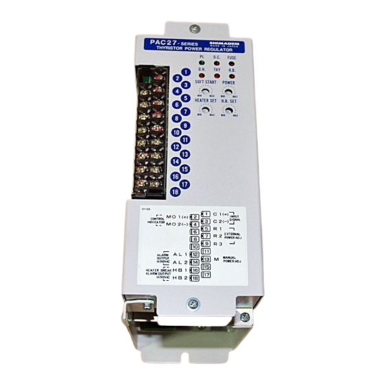
- Page 4 2. Front Panel Information and Control Terminals 2-1. Front Panel Information Names of monitor lamps • PL : Power indicator • O.C. : Overcurrent protection action indicator • FUSE : Rapid fuse fusing indicator (option) • O.H. : Thyristor overheating alarm indicator •...
-
Page 5: Installation Site
3. External Dimensions, Terminal Sizes and Masses 3-1. 20A / 30A, 45A / 60A Mass 20A, 30A : About 2.2kg 45A, 60A : About 3.1kg Current 20A / 30A 45A / 60A Code W [mm] D [mm] B [mm] 3-2. 80A / 100A Mass 80A, 100A : About 4.4kg 4. - Page 6 5. Mounting Safety should be taken well into consideration in using this instrument by fixing it to a control panel, wall or rack so as to keep it from easy contact with persons. It has to be installed vertically for heat radiation, leaving more than 100 mm spaces above and below it respectively. If it is inevitable to install the instrument horizontally, it must be used with less than 70% of the rated current.
- Page 7 6. Circuit Block Diagram and Terminal Marking Terminal Marking ― Control Terminal No.1–18 (See Page 4. 2-2) Power / Load Circuits...
- Page 8 7-3. Wiring for Power Supply and Load Three terminal wiring configurations are carried out for the PAC27; M4 for 20A-30A, 3P terminal board of M5 for 45A-60A, and bar 2 terminals of M8 & 1P terminal board of M4 for 80A-100A. Select proper terminals and tighten screws firmly.
- Page 9 When the allowable range of load resistance of the 4-20mA output controller is 600Ω, maximum of six units can be connected. Since PAC27 units have control circuits of different electric potentials, auto and manual have to be switched individually. 9. Alarm Function (standard equipment) 9-1.
- Page 10 The power adjuster allows adjusting thyristor output in a range from 0% to 100% when the control input signal is at 100%. Power adjuster can change PAC27 output ramping with respect to control output signals. 10-2. Soft Start Time Adjustment Soft start is the function to delay thyristor output with respect to a change in control input signal.
- Page 11 110W 11-2. Ambient Temperature and Load Current The current rated for the PAC27 is at 50 ºC of ambient temperature. In case ambient temperature exceeds 50 ºC, the instrument should be used with load current as illustrated below. 11-3. Control System and Output Waveform Phase control system 11-4.
- Page 12 When the product is used with noise filter and wired as specified by the instruction manual, the product meets the requirement of EMC command. 1. For dealing with EMC command Use in combination with a noise filter designed by us. Install the noise filter on the same metal plate as the PAC27. Do not forget to properly ground it.
- Page 13 Do not put the transformer in operation when its load remains open. You should not switch the load while the transformer is energized. If you do this, the soft start function will not work, resulting in generation of excessive current or activation of the protection circuit of the PAC27.
- Page 14 14. Wiring and Use of Additional Functions (Option) This section applies to the instrument which has an optional function. 14-1. Output Adjusting Functions (5 types of manual adjuster) Any of these functions can be used when an external adjuster (B 10kΩ variable resistor) is connected to a terminal. It is possible to add the functions even after the instrument has been delivered.
-
Page 15: Heater Break Alarm
2) Setting of Heater Set - Setting of heater capacity Turn VR of the Heater Set clockwise slowly and gradually while the PAC27 output voltage is at 50% or above, and set it at the position on which the HB lamp lights. - Page 16 Even for pure metal heaters with large rush current, the use of the current control function (option) is not required. Because current corresponding to a control input signal is tried to output, a power regulator is used for regulation if the capacity of the PAC27 does not match with that of the heater.
-
Page 17: Current Limiting Function
14-4. Current Limiting Function This is the function to limit output current within a range from 50 to 100% of the rated current of the PAC27. In case a pure metal heater or a lamp heater, i.e., a load with large rush current is used, this function is employed to protect thyristor by limiting rush current or to limit load current for some other purposes. -
Page 18: Specifications
15. Specifications Control element configuration: Additional functions (Common options) Thyristor (SCR) x 2 Anti-parallel connection Rapid fuse: with alarm output External power Adjustment functions: External power Manual power High/low Power supply power High power 100-110V, 110-120V, 200-220V, 220-240V AC Low power 10% 50/60Hz External power + manual power Heater break alarm: To be set at 0 to 100% of rated current... -
Page 19: Troubleshooting
2) In the case of load with large Set longer time for soft start. If it does not work, add current limiting protective circuit rush current such as pure metal function (option) or replace PAC27 with one which has a larger current (O.C.) is activated heater. rating. - Page 20 The contents of this manual are subject to change without notice. Temperature and Humidity Control Specialists Head Office: 2-30-10 Kitamachi, Nerima-ku, Tokyo 179-0081 Japan Phone: +81-3-3931-7891 Fax: +81-3-3931-3089 E-MAIL: exp-dept@shimaden.co.jp URL: http://www.shimaden.co.jp...
Need help?
Do you have a question about the PAC27 and is the answer not in the manual?
Questions and answers