Table of Contents
Advertisement
Advertisement
Table of Contents

Related Manuals for Allegion interflex IF-4072


Summary of Contents for Allegion interflex IF-4072
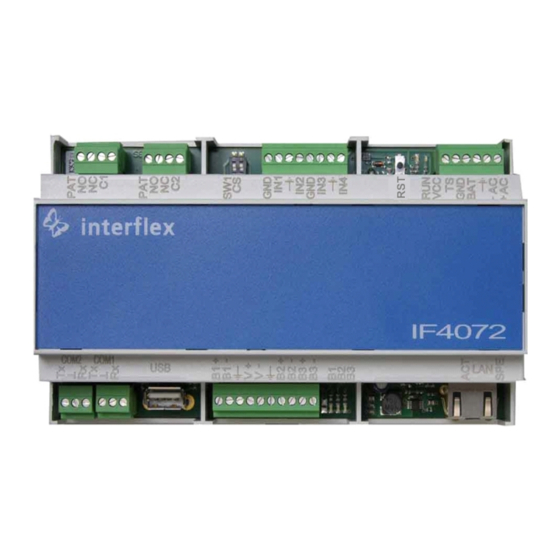
- Page 1 Controller IF-4072 Controller 00-4072-04xx...
-
Page 2: Table Of Contents
Table of contents General information......................Short description....................... Scope of delivery ...................... Target group ......................Intended use ......................Safety........................Abbreviations ......................Cable lengths and cable types.................. System overview........................Range of functions....................IF-4072 controller overview ..................Mounting the controller....................... 10 Connecting the controller ....................10 Wiring components .................... - Page 3 Disposal ..........................23 Declarations of conformity ....................24 10.1 EU Declaration of Conformity ................... 24 10.2 UK Declaration of Conformity ................... 24 © 2022 Interflex Datensysteme GmbH | IF-4072 Controller | 06.22...
-
Page 4: General Information
1 General information 1 General information 1.1 Short description The controller IF-4072 is used to connect up to 16 Interflex terminals for time & attendance recording or access control to the host system. Two integrated relays and four input contacts allow for the control and monitoring of doors, for example. -
Page 5: Safety
1 General information Any other use is not in accordance with the intended purpose and therefore not permitted. Modifications to the device are not permitted. 1.5 Safety NOTICE Property damage due to transient overvoltages Transient overvoltages (surges, bursts) in the energy supply network can lead to malfunctions and failures. -
Page 6: Cable Lengths And Cable Types
1 General information RFID Radio-Frequency Identification Shield Secure shell 1.7 Cable lengths and cable types Cable function Max. length Recommended cable type 230 V AC power supply to power supply unit (if not NYM 3 x 1.5 mm pre-installed) Network cable: RJ45 patch cable, preferably 100 m From category 5 shield braiding... -
Page 7: System Overview
2 System overview 2 System overview Controller Inputs for floating status contacts Relay with 30V, 2A switch contacts Switch or PoE device Host system Terminals for recording time data Terminal for access control Locking device with access control actuator and status contact Terminals for recording time data 2.1 Range of functions Main functions of the If-407x controllers:... -
Page 8: If-4072 Controller Overview
2 System overview Field of application The controllers are operated with the IF-6020 or IF-6040 host system and control up to 16 Interflex terminals for time & attendance recording or access control that are distributed among three RS485 interfaces. The controllers check the booking data recorded by the terminals and transfer it to the host system in real-time. - Page 9 2 System overview USB connection (for future use) 3-pin for RS232 service device Host connection via serial interface (RS232) LEDs, push-buttons and switches Description Function Factory reset: Save IP address settings temporarily and set default IP address to 172.18.70.52. Delete stored data, restore standard parameters Cancel active processes, trigger restart Status Operating mode of the controller...
-
Page 10: Mounting The Controller
3 Mounting the controller 3 Mounting the controller NOTICE Damage to property due to manipulation of the controller Manipulation of the controller can lead to data loss. Install the controller in the secured area, taking the technical requirements into account Mount the controller on a TS35 DIN rail, e.g. - Page 11 4 Connecting the controller BUS 3- BUS 3+ BUS 2- BUS 2+ BUS 1- BUS 1+ You can find further information on how to connect the bus data cables in the section IF-4072 controller overview [} 8]. Floating status contacts and relays Relays 230 V Status contacts...
-
Page 12: Connecting The Power Supply
4 Connecting the controller Connect the cable shields as shown in the diagram to maintain the required EMC values. 4.2 Connecting the power supply NOTICE Malfunction due to improper electrical installation Improper electrical installation can lead to malfunctions in operation and equipment failures. Therefore, please note the following: Use shielded cables Cable lengths and cable types [} 6]... -
Page 13: Initial Operation
5 Initial operation To comply with the specified EMC limits, the controller requires functional grounding via the PoE device and the patch cable. Procedure Make sure that the PoE device is functionally grounded Ground PoE devices without functional grounding via existing soldering lugs or screw terminals Ground the shields of the bus cables via terminal strip KL.4 Redundant power supply... -
Page 14: Connecting The Controller To The Network
5 Initial operation Service interface IF-4070 controller 75-4070-0002 service cable 4xxx (connection via RJ45) IF-5xxx terminal 75-99-0006 Service cable 5xxx 5.1 Connecting the controller to the network You can connect the controller to the network via a service cable and the serial service interface or via WLAN with the IF-ServiceApp. -
Page 15: Checking And Setting Network Parameters
5 Initial operation 7. Define a password Details on valid password requirements and how to change a password can be found underUsers and passwords. Only after entering a password are the network services started and the network connection can be established. Establish network connection After the power supply has been switched on, the component executes the following actions: Boot the operating system... - Page 16 5 Initial operation Setting the network parameters Via the netpar -x command, you can retrieve information on the current network parameters (e.g. the IP address and port), which you can then change. When assigning the IP address and setting up the network, observe the current state-of-the- art technology for securing and segmenting corporate networks.
-
Page 17: Configuring The Interfaces And The Booking Memory
5 Initial operation Perform a factory reset. Further information can be found in the section Restarting the controller [} 19]. 5.3 Configuring the interfaces and the booking memory Via the command oc -h, you can change interface settings adjust the size of the booking memory Press the Enter key to confirm values that you do not wish to change. -
Page 18: Listing The Configuration Data Of Terminals
5 Initial operation 5.4 Listing the configuration data of terminals The cfg command lists the configuration data of terminals. fieldservice@IF xxxx:~ cfg Terminal configuration IF xxxx/4735 IT-2018.02.0-794-g91e557d6d26e Host: Ethernet ---------------------------------------------------------------- No B A HA TNo type HWU SWU display keys read.1 read.2 In/Out I/O -- - - -- --------- ------- ----- ----- ------- ------ ------ -- 1 1 A 1 0 IF611 3.00 7.b ../.. -
Page 19: Restarting The Controller
5 Initial operation 5.5 Restarting the controller Some changes require a restart of the controller. You can do this directly on the controller or with the appropriate commands via the console. Warm boot A warm boot performs the following actions: Close application Restart application Associated console command: oc -s or factory-reset application-restart... - Page 20 5 Initial operation 3. Wait until the RUN LED lights up again permanently (procedure can take up to 45 seconds) 4. Reset switch position: Associated console command: oc -c oder factory-reset application Reset network settings to factory default The network settings are reset. 1.
-
Page 21: Updating The Software
6 Updating the software 6 Updating the software There are two ways to update the controller software: Via the IF-6040 system (version 8.3 or higher) Via the PuTTY program package using batch files Preparation To update the software on the controller via batch files, the current version of the Putty program package must be installed on the service PC. -
Page 22: Upgrading The Controller
7 Upgrading the controller 7 Upgrading the controller The functional scope of a controller depends on the purchased license. You can extend (upgrade) this license, if necessary. Example: Upgrading an IF-4070 controller with 8 terminals to a controller with 16 terminals After ordering an upgrade, you will receive two files from Interflex: Batch file s_tclicence.bat License file *.xml... - Page 23 9 Disposal Weight Approx. 0.3kg Housing material PC, UL 94-0 Installation type EN60715 TH35 mounting rails (size 9 modules) Connections Nominal voltage 18 – 24 V AC/DC Operating status indicators 7 LEDs on front panel Operating status indicators RJ45 sockets or screw terminals for cables up to 0.5 mm² Power supply via Ethernet PoE IEEE 802.3at of power class 4 (up to 25.4 W) Ambient temperature...
- Page 24 The original manual is in German. Other languages are translations of the original manual. Version: 06.22 Interflex Datensysteme GmbH +49 711 1322 - 0 Epplestraße 225 (Haus 3) interflex.info@allegion.com 70567 Stuttgart, Germany www.interflex.com © 2022 Interflex Datensysteme GmbH | All specifications are subject to change without notice.
Need help?
Do you have a question about the interflex IF-4072 and is the answer not in the manual?
Questions and answers