Table of Contents
Advertisement
Quick Links
Advertisement
Table of Contents

Subscribe to Our Youtube Channel
Related Manuals for Allegion interflex IF-4070


Summary of Contents for Allegion interflex IF-4070
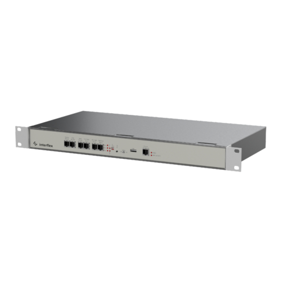
- Page 1 Controller IF-4070 Controller 00-4070-04xx...
-
Page 2: Table Of Contents
Table of contents General information......................Short description....................... Scope of delivery ...................... Target group ......................Intended use ......................Safety........................Abbreviations ......................Cable lengths and cable types.................. System overview........................Range of functions....................Electronic assembly units ..................IF-4070 controller overview ..................Mounting the controller....................... 10 Connecting the controller .................... - Page 3 Upgrading the controller ..................... 24 Technical specifications ..................... 24 Disposal ..........................25 Declarations of conformity ....................26 10.1 EU Declaration of Conformity ................... 26 10.2 UK Declaration of Conformity ................... 26 © 2022 Interflex Datensysteme GmbH | IF-4070 Controller | 06.22...
-
Page 4: General Information
1 General information 1 General information 1.1 Short description The controller IF-4070 is used to connect up to 16 Interflex terminals for time & attendance recording or access control to the host system. Eight integrated relays and eight input contacts allow for the control and monitoring of doors, for example. -
Page 5: Intended Use
1 General information 1.4 Intended use The controller is designed for transferring the recorded data to the access control system and for controlling the connected components in accordance with the specifications in section Technical specifications Any other use is not in accordance with the intended purpose and therefore not permitted. Modifications to the device are not permitted. -
Page 6: Cable Lengths And Cable Types
1 General information Electromagnetic Compatibility Electrostatic discharge Ground IEEE Institute of Electrical and Electronics Engineers NC contact Normally closed contact NO contact Normally open contact Power over Ethernet RFID Radio-Frequency Identification Shield Secure shell 1.7 Cable lengths and cable types Cable function Max. -
Page 7: System Overview
2 System overview 2 System overview Controller Inputs for floating status contacts Relay with 30V, 2A switch contacts Switch or PoE device Host system Terminals for recording time data Terminal for access control Locking device with access control actuator and status contact Terminals for recording time data ©... -
Page 8: Range Of Functions
2 System overview 2.1 Range of functions Main functions of the If-407x controllers: Field of application The controllers are operated with the IF-6020 or IF-6040 host system and control up to 16 Interflex terminals for time & attendance recording or access control that are distributed among three RS485 interfaces. -
Page 9: If-4070 Controller Overview
2 System overview 2.3 IF-4070 controller overview Connections on the printed circuit board USB connection (for future use) 14-pin screw terminal for floating input contacts 14-pin screw terminal for floating input contacts and relay contacts 14-pin screw terminal for relay contacts 6-pin screw terminal for relay contacts Screw terminal for the connection of the power supply RJ45 socket for the connection to the Ethernet network (host system) -
Page 10: Mounting The Controller
3 Mounting the controller LEDs and switches Status Operating mode of the controller Bus 1 / 2 / 3 Lights up Data exchange with terminal on bus 1 / 2 / 3 Lights up Application has been started; controller is ready for operation LINK Flashing Network data exchange... -
Page 11: Connecting The Controller
4 Connecting the controller The illustration shows the installation with housing brackets in a 19” cabinet. The angle brackets allow the controller to be pulled out and hooked into the rack, e.g. to connect cables. You can also mount the controller onto a wall using the device brackets. Without brackets, the device can also be placed on a tabletop or even stacked. - Page 12 4 Connecting the controller Bus cables with terminals You can connect up to 8 terminals to each bus interface. A maximum of 16 terminals can be connected to the controller. Always connect a terminal with address 1 to bus 1. Evenly distribute the terminals among the three bus interfaces.
- Page 13 4 Connecting the controller Up to 8 electrical devices that can be switched via relay, such as e.g. electrical door openers or signal lamps up to 30V 2A. NO or NC contacts can be used for switching. Connection relays Connection entries Example: Screw terminal 802 Door opener...
-
Page 14: Connecting The Power Supply
4 Connecting the controller Screw terminals for floating outputs (relays) Relay 1 Relay 2 Relay 3 Relay 4 Relay 5 Relay 6 Relay 7 Relay 8 2 NO 1 NO 4 NO 7 NO 10 NO 13 NO 2 NO 5 NO contacts contacts... -
Page 15: Initial Operation
5 Initial operation Redundant power supply To supply the controller with redundant power, you need an external 18 V DC ; 1 A power supply unit. Should the power supply via Ethernet (PoE) fail, the controller automatically switches to power supply via power supply unit. - Page 16 5 Initial operation IF-ServiceApp Prerequisites ü Controller is connected to the IF-ServiceApp. Detailed information on this subject can be found in the documentation of the IF-ServiceApp. Service interface Accessing the controller via SSH requires the freeware PuTTY version 0.73 or higher: 1.
-
Page 17: Checking And Setting Network Parameters
5 Initial operation Leave PuTTY open during the next steps as further entries are required during initial operation. 5.2 Checking and setting network parameters The netpar -? command lists the call parameters of the netpar command: fieldservice@IF‑xxx:~ netpar -? Display or change network parameters (legacy) Please consider using nmtui or nmcli instead. -
Page 18: Configuring The Interfaces And The Booking Memory
5 Initial operation fieldservice@IF‑xxx:~ netpar -x IPv4 address/netmask [172.18.12.65/16]: IPv4 gateway [172.18.70.1]: Port [2001]: Hostname [IF‑xxx]: Connection 'netpar' (e046c1c5-2eb5-4be0-8655-4f79acffc8bc) successfully deleted. Connection 'netpar' (8ff8bd2e-7229-4914-a214-3d60dc0e7f16) successfully added. Activate profile netpar Connection successfully activated (D-Bus active path: /org/freedesktop/ NetworkManager/ActiveConnection/3) Current profile: netpar IPv4 address/netmask: 172.18.12.65/16 IPv4 gateway: 172.18.70.1 IPv4 address/netmask (active): 172.18.12.65/16... - Page 19 5 Initial operation fieldservice@IF xxxx:~ oc -h base address : 1 No. of term. bus 1 : 6 bus 2 : 4 bus 3 : 6 IF LT64 at bus 2 : 0 Protocol bus 1 : 0 bus 2 : 0 bus 3 : 0 KryptAddr bus 1, 2, 3: 0xFF Baudrate bus 1 : 3...
-
Page 20: Listing The Configuration Data Of Terminals
5 Initial operation 5.4 Listing the configuration data of terminals The cfg command lists the configuration data of terminals. fieldservice@IF xxxx:~ cfg Terminal configuration IF xxxx/4735 IT-2018.02.0-794-g91e557d6d26e Host: Ethernet ---------------------------------------------------------------- No B A HA TNo type HWU SWU display keys read.1 read.2 In/Out I/O -- - - -- --------- ------- ----- ----- ------- ------ ------ -- 1 1 A 1 0 IF611 3.00 7.b ../.. -
Page 21: Restarting The Controller
5 Initial operation 5.5 Restarting the controller Some changes require a restart of the controller. You can do this directly on the controller or with the appropriate commands via the console. Warm boot A warm boot performs the following actions: Close application Restart application Associated console command: oc -s or factory-reset application-restart... - Page 22 5 Initial operation Cold boot All settings made on the controller via IF-6040 or OC Task are deleted or reset to default. System or operating system settings, such as the IP address or password, are retained. Use the cold boot during initial operation and in the event of malfunctions that cannot be remedied by other means, e.g., a warm boot.
-
Page 23: Updating The Software
6 Updating the software Factory reset All factory settings are restored. For initial operation, the controller can then only be accessed via a serial console or the IF- ServiceApp. 1. Set switches: 2. Shortly press the Reset button 3. Wait until the RUN LED lights up again (procedure can take up to 30 seconds) 4. -
Page 24: Upgrading The Controller
7 Upgrading the controller 7 Upgrading the controller The functional scope of a controller depends on the purchased license. You can extend (upgrade) this license, if necessary. Example: Upgrading an IF-4070 controller with 8 terminals to a controller with 16 terminals After ordering an upgrade, you will receive two files from Interflex: Batch file s_tclicence.bat License file *.xml... -
Page 25: Disposal
9 Disposal Inputs 8 inputs for floating inputs Debounce time of contacts at least 100 ms Output relay/switching capacity 8 relays with 'normally closed’ (NC) and 'normally open’ (NO) contacts Switching capacity up to 30 V, 2 A Operating status indicators 7 LEDs on front panel General data Ambient temperature... -
Page 26: Declarations Of Conformity
The original manual is in German. Other languages are translations of the original manual. Version: 06.22 Interflex Datensysteme GmbH +49 711 1322 - 0 Epplestraße 225 (Haus 3) interflex.info@allegion.com 70567 Stuttgart, Germany www.interflex.com © 2022 Interflex Datensysteme GmbH | All specifications are subject to change without notice.
Need help?
Do you have a question about the interflex IF-4070 and is the answer not in the manual?
Questions and answers